

Page 1

5XI SERIES TRACTOR HYDRAULIC SYSTEMS SERVICE MANUAL
Table of Contents – Page 1 of 2
SAFETY INFORMATION
GENERAL INFORMATION
THINK SAFETY FIRST
SPECIFICATIONS
TRANSMISSION (EATON MODEL)
TRANSAXLE (WHEEL HORSE)
5XI AUTOMATIC TRANSMISSION SYSTEM SPEEDS
OIL
BOLT TORQUE
EPOXY PATCH SCREWS
SINGLE-USE FASTENERS
CRITICAL FASTENERS
MAINTENANCE
SERVICE SCHEDULE TABLE
TRANSAXLE FLUID
GENERAL INFORMATION
CHECKING FLUID LEVEL
FLUID CHANGE
FILTER CHANGE
BRAKE
GENERAL INFORMATION
ADJUSTMENT
NEUTRAL ADJUSTMENT
GENERAL INFORMATION
ADJUSTMENT PROCEDURE
POWER STEERING
GENERAL INFORMATION
TROUBLESHOOTING
THEORY OF OPERATION
GENERAL INFORMATION
TRANSMISSION OPERATION
HYDROSTATIC TRANSMISSION FLOW DIAGRAM WITH POWER STEERING
HYDROSTATIC TRANSMISSION FLOW DIAGRAM WITHOUT POWER STEERING
POWER STEERING CYLINDER HYDRAULIC HOSE ROUTING
LIFT CYLINDER HYDRAULIC HOSE ROUTING
HYDROSTATIC TRANSMISSION FLOW DIAGRAM, UNITS WITHOUT POWER STEERING
TROUBLESHOOTING TABLES
TRACTOR WILL NOT OPERATE IN EITHER DIRECTION; ENGINE BOGS DOWN OR STALLS
TRACTOR GOES FORWARD ONLY AT PARTIAL SPEED AND IS SLOW OR DOES NOT OPERATE IN REVERSE
TRACTOR WILL NOT OPERATE IN EITHER DIRECTION
TRACTOR OPERATES ERRATICALLY
TRACTOR OPERATES IN BOTH DIRECTIONS BUT WITH LOSS OF POWER (WORSENS AS BECOMES HOT)
Page 2

5XI SERIES TRACTOR HYDRAULIC SYSTEMS SERVICE MANUAL
Table of Contents – Page 2 of 2
TROUBLESHOOTING TABLES - Continued
TRANSMISSION OVERHEATING
ABNORMAL VIBRATION OR NOISE
HYDRAULIC LIFT SYSTEM DOES NOT OPERATE OR DOES NOT OPERATE PROPERLY
OIL IS LEAKING OUT HIGH-LOW SHIFT FORK HOLE DURING OPERATION
TROUBLESHOOTING FLOW CHARTS
TRACTOR WILL NOT OPERATE IN EITHER DIRECTION
TRACTOR OPERATES, BUT LOSES POWER AS OIL BECOMES HOT AND/OR TRANSMISSION OVERHEATS
TRACTOR DOES NOT RETURN TO NEUTRAL
TRACTOR OPERATES NORMALLY IN ONE DIRECTION, BUT IS VERY SLOW IN OPPOSITE DIRECTION
TRACTOR OPERATES IN ONLY ONE DIRECTION
TRACTOR OPERATES ERRATICALLY
HYDRAULIC LIFT SYSTEM DOES NOT OPERATE, OR DOES NOT OPERATE PROPERLY
HYDRAULIC SYSTEMS TESTING
TESTING SYSTEM PERFORMANCE
PRESSURE CHECKS
LIFT SYSTEM PRESSURE
CHARGE PRESSURE
REPAIR PROCEDURES
CHASSIS
REAR FENDERS, FOOTRESTS, & TUNNEL
GENERAL INFORMATION
TRANSAXLE R & R
REMOVAL
REASSEMBLY
SMART TURN™ LINKAGE ADJUSTMENTS
HYDROSTATIC DRIVE
TRANSMISSION/TRANSAXLE
DISASSEMBLY
DIFFERENTIAL DISASSEMBLY
REASSEMBLY
HYDROSTATIC TRANSMISSION
TRANSMISSION DISASSEMBLY
REASSEMBLY
HYDRAULIC SYSTEMS
LIFT CYLINDER R & R
LIFT CYLINDER DISASSEMBLY / REASSEMBLY
STEERING CYLINDER R & R
POWER STEERING CY LINDER DISASSEMBLY / REASSEMBLY
POWER STEERING VALVE R & R
POWER STEERING VALVE DISASSEMBLY / REASSEMBLY
STEERING VALVE DISASSEMBLY
REASSEMBLY
LIFT VALVE R & R
Page 3

TORO
®
5xi Series Tractor
Hydraulic Systems
Service Manual
Page 4

ABOUT THIS MANUAL
This service manual was written expressly for Toro Wheel Horse 5xi series garden tractors. The Toro Company has
made every effort to make the information in this manual complete and correct.
This service and repair manual has been compiled to provide authorized Wheel Horse service personnel with the
proper procedures and techniques for servicing the Wheel Horse automatic transaxle with Eaton Model 11
hydrostatic transmission. Basic mechanical/electrical skills are assumed. The Table of Contents lists the systems
and the related topics covered in this manual.
It is advisable to read all the introductory sections first to gain a proper understanding of the Wheel Horse
automatic transmission system.
For information on the electrical system, please refer to the Toro Electrical Demystification Guide (492-4404). For
general service procedures, refer to the 5xi Series Tractor Service Manual (492-4715). For information specific to
the engines used on these garden tractors, refer to the appropriate engine manufacturer’s service and repair
instructions.
We are hopeful that you will find this manual a valuable addition to your service shop. If you have any questions or
comments regarding this manual, please contact us at the following address:
The Toro Company
Consumer Service Training Department
8111 Lyndale Avenue South
Bloomington, MN 55420
The Toro Company reserves the right to change product specifications or this manual without notice.
The automatic transmission and transaxle are sophisticated pieces of machinery. Maintain strict cleanliness
control during all stages of service and repair. Cover or cap all hose ends and fittings whenever they are exposed.
Even a small amount of dirt or other contamination can severely damage the system.
NOTE: This manual uses the terms “transmission, hydrostatic transmission, and hydrostatic unit” to refer to the
Eaton Model 11 Hydrostatic Transmission. The term “transaxle” is used to refer to the assembly of intermediate
gears, differential and case halves, less hydrostatic unit. “Transmission System” and “Automatic Transmission
System” are used to refer to entire drive train as an assembly, including engine, transmission, transaxle, hydraulic
lift system, and all related parts.
Copyright© All Rights Reserved
©1999 The Toro Company
Page 5

QUICK REFERENCE SECTION
TABLE OF CONTENTS
Safety Information . . . . . . . . . . . . . . . . . . . . . . . . . . . . . . . . . . . . . . . . . . . . .
Specifications . . . . . . . . . . . . . . . . . . . . . . . . . . . . . . . . . . . . . . . . . . . . . . . . .
Maintenance. . . . . . . . . . . . . . . . . . . . . . . . . . . . . . . . . . . . . . . . . . . . . . . . . . .
TROUBLESHOOTING
Theory of Operation. . . . . . . . . . . . . . . . . . . . . . . . . . . . . . . . . . . . . . . . . . . . . .
Troubleshooting Tables. . . . . . . . . . . . . . . . . . . . . . . . . . . . . . . . . . . . . . . . . . .
Troubleshooting Flow Charts. . . . . . . . . . . . . . . . . . . . . . . . . . . . . . . . . . . . . . .
Hydraulic Systems Testing . . . . . . . . . . . . . . . . . . . . . . . . . . . . . . . . . . . . . . . .
1a
1b
1c
2
3
4
5
REPAIR PROCEDURES
Chassis . . . . . . . . . . . . . . . . . . . . . . . . . . . . . . . . . . . . . . . . . . . . . . . . . . . . . . .
Hydrostatic Drive . . . . . . . . . . . . . . . . . . . . . . . . . . . . . . . . . . . . . . . . . . . . . . . .
Hydraulic Systems. . . . . . . . . . . . . . . . . . . . . . . . . . . . . . . . . . . . . . . . . . . . . . .
5xi Series Tractor Hydraulic Service Manual 1 - 1
6
7
8
Page 6

QUICK REFERENCE
SAFETY INFORMATION
General Information. . . . . . . . . . . . . . . . . . . . . . . . . . . . . . . . . . . . . . . . . . . . . 1 - 5
Think Safety First. . . . . . . . . . . . . . . . . . . . . . . . . . . . . . . . . . . . . . . . . . . . . . . 1 - 5
SPECIFICATIONS
Transmission (Eaton Model 11) . . . . . . . . . . . . . . . . . . . . . . . . . . . . . . . . . . . 1 - 6
Transaxle (Wheel Horse) . . . . . . . . . . . . . . . . . . . . . . . . . . . . . . . . . . . . . . . . 1 - 6
5xi Automatic Transmission System Speeds . . . . . . . . . . . . . . . . . . . . . . . . . 1 - 6
Oil . . . . . . . . . . . . . . . . . . . . . . . . . . . . . . . . . . . . . . . . . . . . . . . . . . . . . . . . . . 1 - 7
Table of Contents
Bolt Torque . . . . . . . . . . . . . . . . . . . . . . . . . . . . . . . . . . . . . . . . . . . . . . . . . . . 1 - 7
Epoxy Patch Screws . . . . . . . . . . . . . . . . . . . . . . . . . . . . . . . . . . . . . . . . . . . . 1 - 7
Single-Use Fasteners . . . . . . . . . . . . . . . . . . . . . . . . . . . . . . . . . . . . . . . . . . . 1 - 8
Critical Fasteners . . . . . . . . . . . . . . . . . . . . . . . . . . . . . . . . . . . . . . . . . . . . . . 1 - 8
MAINTENANCE
Service Schedule Table. . . . . . . . . . . . . . . . . . . . . . . . . . . . . . . . . . . . . . . . . . 1 - 9
TRANSAXLE FLUID
General Information . . . . . . . . . . . . . . . . . . . . . . . . . . . . . . . . . . . . . . . . . . 1 - 9
Checking Fluid Level . . . . . . . . . . . . . . . . . . . . . . . . . . . . . . . . . . . . . . . . 1 - 10
Fluid Change . . . . . . . . . . . . . . . . . . . . . . . . . . . . . . . . . . . . . . . . . . . . . . 1 - 10
Filter Change . . . . . . . . . . . . . . . . . . . . . . . . . . . . . . . . . . . . . . . . . . . . . . 1 - 11
1 - 2 5xi Series Tractor Hydraulic Service Manual
Page 7

QUICK REFERENCE
BRAKE
General Information . . . . . . . . . . . . . . . . . . . . . . . . . . . . . . . . . . . . . . . . 1 - 11
Adjustment . . . . . . . . . . . . . . . . . . . . . . . . . . . . . . . . . . . . . . . . . . . . . . . 1 - 12
NEUTRAL ADJUSTMENT
General Information . . . . . . . . . . . . . . . . . . . . . . . . . . . . . . . . . . . . . . . . 1 - 12
Adjustment Procedure . . . . . . . . . . . . . . . . . . . . . . . . . . . . . . . . . . . . . . 1 - 13
POWER STEERING
General Information . . . . . . . . . . . . . . . . . . . . . . . . . . . . . . . . . . . . . . . . 1 - 14
5xi Series Tractor Hydraulic Service Manual 1 - 3
Page 8

THIS PAGE INTENTIONALLY LEFT BLANK
1 - 4 5xi Series Tractor Hydraulic Service Manual
Page 9

SAFETY INFORMATION
This symbol means WARNING or
PERSONAL SAFETY INSTRUCTION
- read the instruction because it has to
do with your safety. Failure to comply
with the instruction may result in
personal injury or even death.
This manual is intended as a service and repair manual
only. The safety instructions provided herein
THINK SAFETY FIRST
Avoid unexpected starting of engine...
Always turn off the engine and disconnect the spark
plug wire(s) before cleaning, adjusting, or repair.
Avoid lacerations and amputations...
Stay clear of all moving parts whenever the engine is
running. Treat all normally moving parts as if they were
moving whenever the engine is running or has the
potential to start.
are for troubleshooting, service, and repair of the 5xi
series garden tractor. The tractor and attachment
operator’s manuals contain safety information and
operating tips for safe operating practices. Operator’s
manuals are available through your Toro parts source
or:
The Toro Company
Publications Department
8111 Lyndale Avenue South
Bloomington, MN 55420
Avoid injury from batteries...
Battery acid is poisonous and can cause burns. Avoid
contact with skin, eyes, and clothing. Battery gases can
explode. Keep cigarettes, sparks, and flames away
from the battery.
Avoid injury due to inferior parts...
Use only original equipment parts to ensure that
important safety criteria are met.
1a
Avoid burns...
Do not touch the engine, muffler, or other components
which may increase in temperature during operation,
while the unit is running or shortly after it has been
running.
Avoid fires and explosions...
Avoid spilling fuel and never smoke while working with
any type of fuel or lubricant. Wipe up any spilled fuel or
oil immediately. Never remove the fuel cap or add fuel
when the engine is running. Always use approved,
labeled containers for storing or transporting fuel and
lubricants.
Avoid asphyxiation...
Never operate an engine in a confined area without
proper ventilation.
Avoid injury to bystanders...
Always clear the area of bystanders before starting or
testing powered equipment.
Avoid injury due to projectiles...
Always clear the area of sticks, rocks, or any other
debris that could be picked up and thrown by the
powered equipment.
Avoid modifications...
Never alter or modify any part unless it is a factory
approved procedure.
Avoid unsafe operation...
Always test the safety interlock system after making
adjustments or repairs on the machine. Refer to the
Electrical section in the 5xi Service Manual for more
information.
5xi Series Tractor Hydraulic Service Manual 1 - 5
Page 10

SPECIFICATIONS
Transmission (Eaton Model 11)
Item Description
Radial ball piston pump and motor with auxiliary charge pump
Displacement, Pump Variable 0 - 1.10 cu. in./rev. (18.03 cu. cm)
Displacement, Motor Fixed 2.09 cu. in./rev. (34.2 cu. cm)
1b
Speed, Input 3400 RPM
Speed, Output 0 - 1842 RPM
Torque Output 360 in·lb - Continuous (40.7 N·m)
Torque Output 540 in·lb - Intermittent (61 N·m)
Operating Temperature Maximum continuous 180°
Cooling - Air 8” diameter fan (20.3 cm)
Cooling - Oil Oil flow from charge pump
Oil Filter
Charge Pump
Flow @ 3400 RPM input
Spin-on, Full flow
10 Micron
3.8 GPM (14.4 lpm) free flow
1.4 GPM (5.3 lpm) @ 700 PSI (48.21 bar)
Transaxle (Wheel Horse)
Item Description
Two speed unidrive 8 pinion differential, double reduction gears Gear Ratio 16:1 high; 27:1 low
Gears and Shafts Heat-treated steel
Bearings Ball (2)
Needle (8)
Case Halves and Hubs Cast iron
Seals (3) double-lip, spring-loaded
Overall reduction ratio 30:1 high; 50:1 low
Axle shaft speed 115 RPM @ 1842 RPM trans output, high
68 RPM @ 1842 RPM trans output, low
Tractor Speed, Forward 0 - 7.4 MPH (11.8 km/h)
Tractor Speed, Reverse 0 - 4.35 MPH (6.96 km/h)
5xi Automatic Transmission System Speeds
Engine Speed Brake Shaft Axle Shaft MPH (Kmh)
High Range 3400 RPM 1319 RPM 115 RPM 7.40 (11.9 km/h)
Low Range 3400 RPM 775 RPM 68 RPM 4.35 (7.01 km/h)
1 - 6 5xi Series Tractor Hydraulic Service Manual
Page 11

SPECIFICATIONS
Oil
Item 73470, 73540, 73541 73560, 73545, 73546, 73550, 73551
Capacity 6 Quarts (5.7l) Approx. (refill 4.5 Quarts (4.3l)) 7 Quarts (6.6l) Approx. (refill 4.5 Quarts (4.3l))
Type
10W-30 or 10W-40
API service SH or higher
Bolt Torque
Size - Thread Pitch Torque
1/4 - 20 8 ft·lb (.9 N·m)
5/16 - 18 17 - 22 ft·lb (23 - 30.8 N·m)
3/8 - 16 30 - 35 ft·lb (42 - 49 N·m)
1/2 - 13 75 - 80 ft·lb (105 - 112 N·m)
Wheel Hub Set Screw 28 - 32 ft·lb (39.2 - 44.8 N·m)
10W-30 or 10W-40
API service SH or higher
1b
Epoxy Patch Screws *
Torque Value
Part Number Description/Where Used
94-7817 Shoulder bolt connects the Smart Turn linkage to the transaxle
control assembly
94-7972 Torque strap bolt to transaxle 27 - 33 36.6 - 44.7
94-7955 Transmission cooling fan center bolt 90 - 120 10.2 - 13.6
94-7973 Electric PTO clutch bolt - for Kohler and Vanguard diesel engines 50 - 60 67.8 - 81.4
94-7974 Electric PTO clutch bolt - for Kawasaki engine 50 - 60 67.8 - 81.4
94-7975 Driveshaft coupling set screws 120 - 160 13.6 - 18.8
94-7976 Bolt connects the power steering cylinder to the steering arm 40 - 50 54.2 - 67.8
95-4183 Bolt to attach the iso-mount brackets to Vanguard diesel engine 17 - 21 23.0 - 28.5
95-4184 Bolt used in various places on Vanguard diesel engine and to
retain the Kawasaki engine to the engine base plate
95-4232 Bolt to attach the rear PTO to the Kawasaki engine 17 - 21 23.0 - 28.5
98-3052 Bolt to attach steering arm to splined shaft 27 - 33 36.6 - 44.7
98-3498 Retaining bolt in bottom of steering pinion (manual steering) 15 - 19 19.8 - 25.4
99-4953 Bolt for 2-speed shifter assembly (starting with 1999 models) 15 - 19 19.8 - 25.4
In-Lbs Ft-Lbs N·m
90 - 120 10.2 - 13.6
17 - 21 23.0 - 28.5
*NOTE: Designed for only one use. Fasteners are not reusable.
5xi Series Tractor Hydraulic Service Manual 1 - 7
Page 12

SPECIFICATIONS
Single-Use Fasteners
1b
Part Number Description/Where Used
911423 &
108881
95-4245 Bolt / nylon patch bolt - Used on front end of lift cylinder; replace,
108881 Nut / Used to attach mid-attach-a-matic side plates to frame;
98-8088 Nut / attach front tie rod end to steering arms; replace, do not
108881 Nut / rear end of power steering cylinder to frame; replace, do not
108881 Nut / used with the power steering tilt assembly pivot bolt; replace,
108881 Nut / slider lift pivot; replace, do not reuse 31 - 37 41.8 - 50.9
108881 Nut / link rod to slider lift pivot; replace, do not reuse 31 - 37 41.8 - 50.9
108881 Nut / parking brake pivot; replace, do not reuse 31 - 37 41.8 - 50.9
108881 Nut / Smart Turn™ pivot assembly; replace, do not reuse 31 - 37 41.8 - 50.9
108881 Nut / magnet plate pivot; replace, do not reuse 31 - 37 41.8 - 50.9
Bolts and nuts / differential assembly; replace when rebuilding 39 - 47 52.9 - 63.7
do not reuse
replace, do not reuse
reuse
reuse
do not reuse
In-Lbs Ft-Lbs N·m
Torque Value
17 - 21 23.2 - 28.8
39 - 47 52.9 - 63.7
40 - 50 54.2 - 67.8
31 - 37 41.8 - 50.9
31 - 37 41.8 - 50.9
Critical Fasteners
Description/Where Used
In-Lbs Ft-Lbs N·m
Bolts / attach transaxle to frame 27 - 33 36.6 - 44.7
Nut / front axle pivot 55 - 75 74.6 - 101.7
Nut / attach rear tie rod end to steering plate 40 - 50 54.2 - 67.8
Bolt / attach brake pivot assembly to transaxle 27 - 33 36.6 - 44.7
Bolt / attach brake drum to brake shaft 27 - 33 36.6 - 44.7
Set screws / rear axle hubs 28 - 32 38 - 43.4
Bolts / L.H. and R.H. transaxle case halves - torque in crisscross sequence 27 - 33 36.6 - 44.7
Bolts / Transmission to transaxle - torque in crisscross sequence 27 - 33 36.6 - 44.7
Bolts / rubber driveshaft couplings 17 - 21 23.1 - 28.8
Nut / speed control arm to transmission control shaft 20 - 24 27.1 - 32.5
Bolts / rear wheel lug bolts 75 - 80 101.7 - 108.5
Bolts 1/2 - 13 / Vanguard diesel iso-mount - FRONT 78 - 94 105.8 - 127.5
Bolts 3/8 - 16 / Vanguard diesel iso-mount - REAR 32 - 38 43.4 - 51.5
Kohler exhaust manifold nuts 150 - 220 17 - 24.90
Kawasaki exhaust manifold nuts 52 - 70 5.9 - 7.9
Daihatsu exhaust manifold nuts 150 - 190 17 - 21.5
Torque Value
1 - 8 5xi Series Tractor Hydraulic Service Manual
Page 13
Service Schedule
Item Interval
Oil Level Check Every 25 hrs.
Oil Change Every 200 hrs.
Oil Filter Change
Clean Power Steering Screen
@ 50 hrs.
Every 200 hrs.
@ 50 hrs.
Every 200 hrs.
MAINTENANCE
@ = initial service
NOTE: Service more frequently under dry/dirty/dusty conditions.
NOTE: When cleaning the unit, use compressed air vs. water to avoid contamination of the transaxle fluid.
TRANSAXLE FLUID
General Information
All models of the 5xi series tractor use the Toro
Wheel Horse transaxle with the Eaton model 11
hydrostatic transmission. The transmission is
equipped with a charge pump which supplies
hydraulic pressure to operate the attachment lift
and power steering on units so equipped. The
charge pump also provides pressurized fluid to
the transmission pump to make up for normal
internal leakage.
FLUID TYPE: SAE 10W-30 or 10W-40 detergent
oil (API service SH or higher).
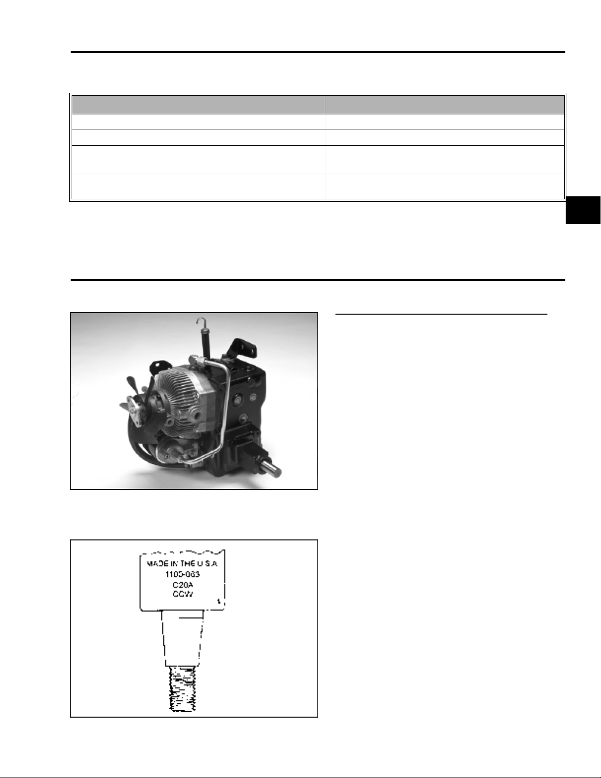
Eaton Model: 1100 - 063.
1c
0144-029
The transmission is stamped with a model
number, manufacturing date code, and direction
of rotation. Rebuilt units are also marked with
the number 1. This information is located on the
case near the control shaft.
0202-001
5xi Series Tractor Hydraulic Service Manual 1 - 9
Page 14
MAINTENANCE
Checking Fluid Level
1. The transaxle fluid level must be checked
when the machine is cold and parked on a
level surface.
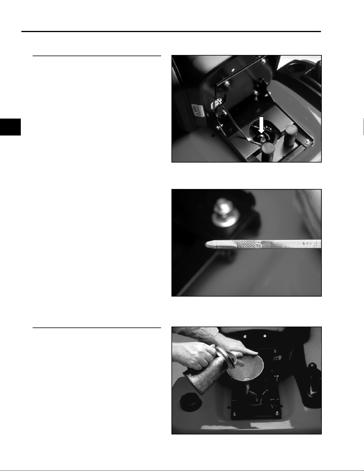
2. Tilt the seat forward.
3. Clean around the dipstick to prevent dirt from
falling into the system when the dipstick is
removed.
1c
NOTE: Allowing dirt in the reservoir may
result in severe damage to the transmission.
0757-015
4. Remove the dipstick. If necessary, add oil to
the FULL line on the dipstick.
IMPORTANT: Do not fill the reservoir above
the FULL line as the reservoir may overflow
after the tractor is stopped and has set for
awhile.
0109-007
Fluid Change
The transaxle fluid should be changed every 200
hours of operation.
Remove the drain plug and drain the transaxle
fluid into a suitable container.
Replace the drain plug, and fill the transaxle to
the FULL mark with 10W-30 or 10W-40
detergent oil with an API service rating of SH or
higher.
System Capacity (refill capacity is 4.5 quarts
(4.3l)):
With power steering: 7 qts. (6.6 l)
Without power steering: 6 qts. (5.6 l)
0415-004
1 - 10 5xi Series Tractor Hydraulic Service Manual
Page 15
0144-031
MAINTENANCE
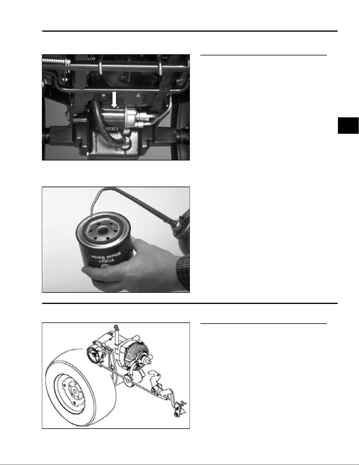
Filter Change
The transaxle is equipped with a 10 micron spinon oil filter. This filter should be changed after
the first 50 hours of operation and then every 200
hours thereafter.
1c
When replacing the filter, coat the gasket with oil.
Tighten until the gasket contacts the base, then
an additional 1/2 turn.
0144-014
BRAKE
General Information
The 5xi series tractor is equipped with an
external band parking brake which is located on
the right side of the transaxle.
When the brake pedal is pressed, the linkage
returns the transmission to neutral, then applies
the brake.
The band brake supplements the transmission’s
dynamic braking to bring the tractor to a stop. It
can also be locked in the applied position and
serves as the parking brake.
7197-067
5xi Series Tractor Hydraulic Service Manual 1 - 11
Page 16
MAINTENANCE
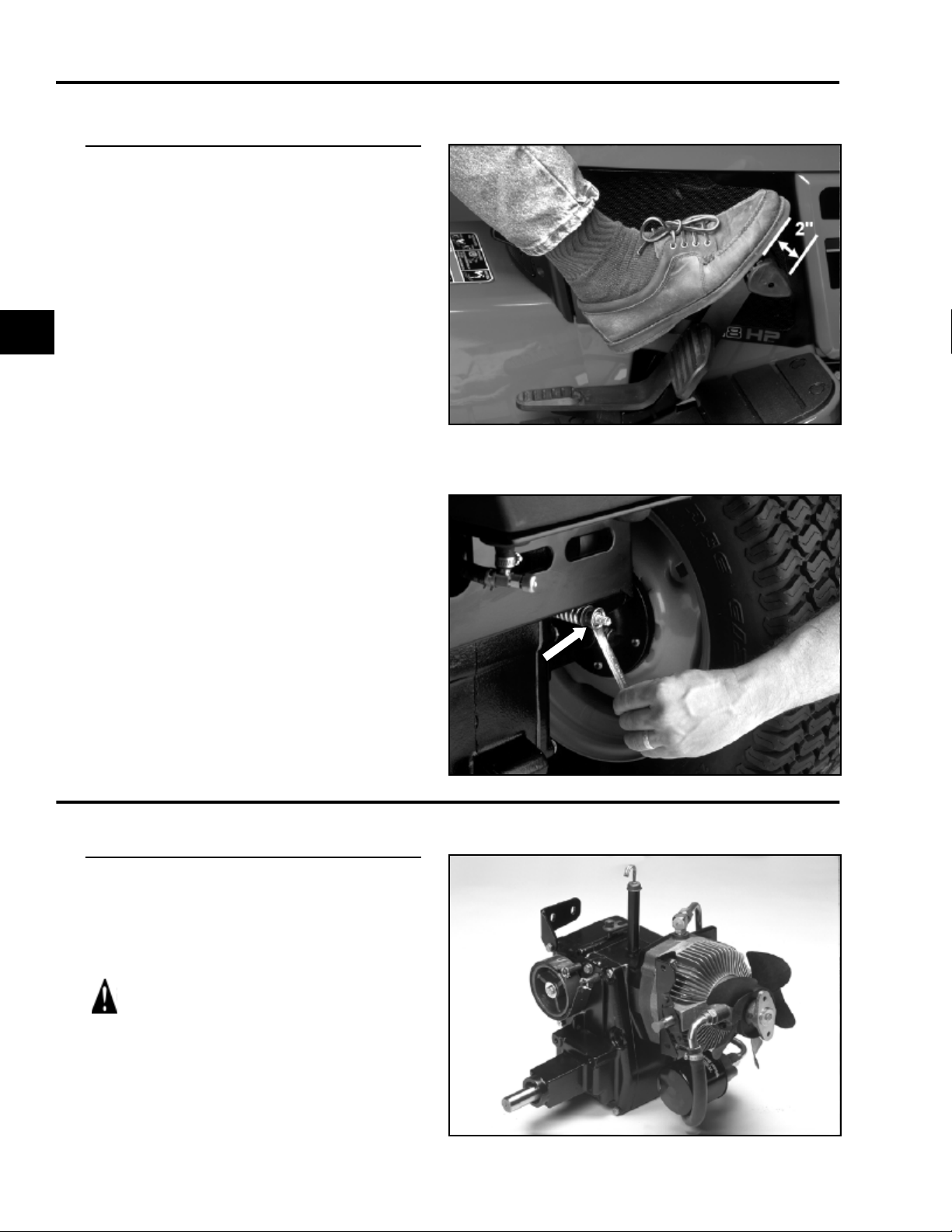
Adjustment
1. Place the transmission in neutral.
2. Depress the brake pedal. There should be
2” (51mm) of free travel before resistance is
felt.
1c
3. Turn the adjustment nut until the above
condition is met.
0109-005
CAUTION: Do not overtighten the
adjustment nut.
NEUTRAL ADJUSTMENT
General Information
The hydrostatic transmission linkage is designed
to be self-centering or “return to neutral”. If the
wheels continue to drive with no pressure on the
control pedal (tractor creeps), neutral adjustment
is required.
CAUTION: The drive shaft and hydrostatic
cooling fan will be spinning. Use extreme
caution to avoid making contact with
moving parts while performing this adjustment.
0109-010
0144-001
1 - 12 5xi Series Tractor Hydraulic Service Manual
Page 17
3653-006
MAINTENANCE
Adjustment Procedure
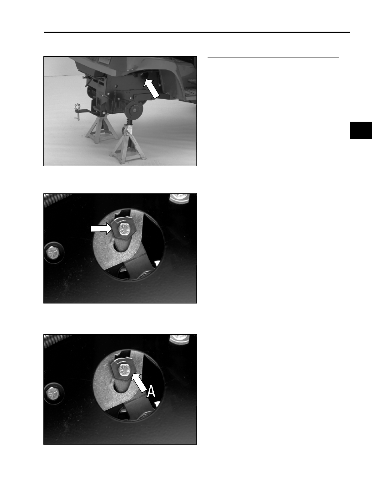
1. Place the rear axle on jack stands, and
remove the rear wheels.
NOTE: Do not set the parking brake.
2. Bring the hydrostatic transmission up to
operating temperature (at least 15 minutes’
operation). The neutral eccentric is
accessed through the hole indicated by the
arrow.
1c
3. To gain access to the adjustment eccentric,
turn the front wheels in either direction to the
steering stop. This causes the linkage rod to
move up, out of the way.
0144-072
4. Loosen the through bolt just enough to allow
rotation of the eccentric (A).
0144-072
5xi Series Tractor Hydraulic Service Manual 1 - 13
Page 18
MAINTENANCE
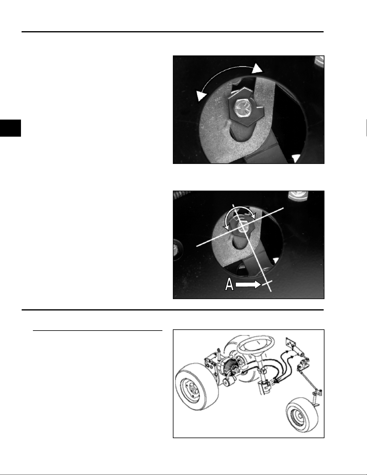
5. With the engine running, rotate the eccentric
until the right rear wheel hub begins to turn.
Note the position of the eccentric. Rotate the
eccentric in the opposite direction until the
wheel hub again begins to turn.
1c
6. Center the eccentric between these points,
and tighten the through bolt while holding the
eccentric.
0144-071
(A) Pivot Point
NOTE: Do not turn the eccentric more than
90° in either direction. Notch in eccentric
must be away from pivot point of control arm.
POWER STEERING
General Information
The 22 HP, 20 HP liquid-cooled and 23 HP
diesel tractors are equipped with power steering.
This system routes pressurized transaxle fluid
supplied by the hydrostatic transmission to a
directional valve located at the base of the
steering column. When the steering wheel is
turned, this valve directs pressure to a double
acting hydraulic cylinder, causing the steering
plate to pivot as the cylinder extends or
contracts. Tie rods attached to the steering plate
turn the front spindles.
144-072
NOTE: A noisy or sluggish hydraulic system
could be caused by a dirty power steering filter.
7195-029
1 - 14 5xi Series Tractor Hydraulic Service Manual
Page 19
0109-044
MAINTENANCE
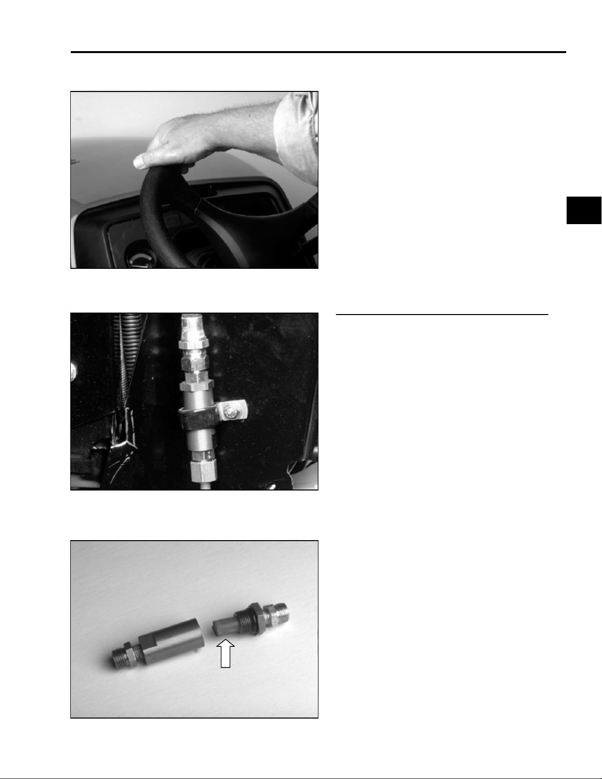
When the tractor is not running, some oil will
drain from the power steering system. On
engine start-up, purge air from the system by
turning the steering wheel fully left and right, at
full engine rpm, until full steering performance is
restored.
1c
Maintenance
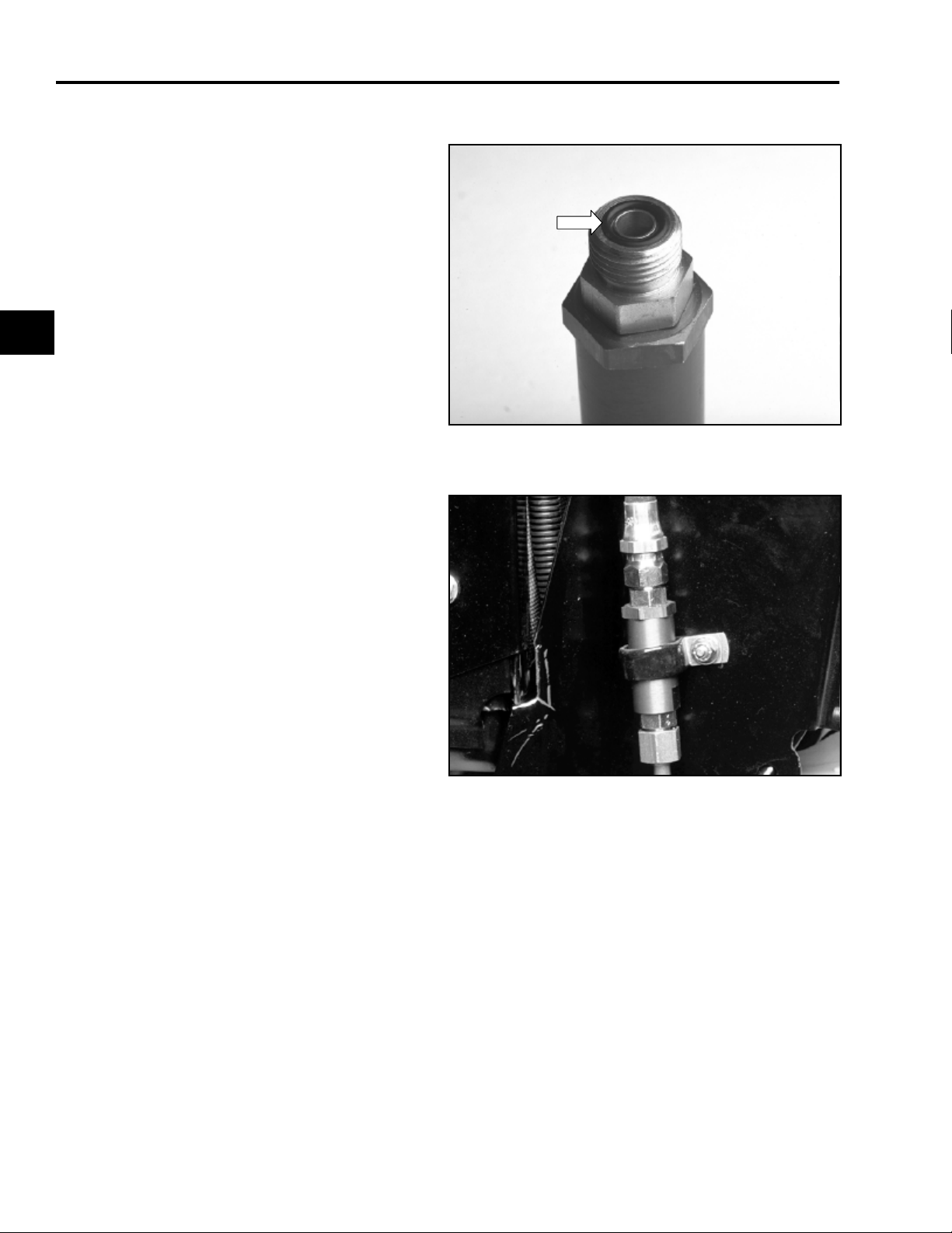
The power steering system is equipped with an
in-line filter screen. It should be cleaned after the
initial 50 hours, then every 200 hours, or if the
power steering gets noisy.
To clean the power steering screen:
1. Remove the left and center air intake
screens.
2. Remove the screen housing from the clamp
securing it to the left-hand side of the
steering tower.
3. Remove the top hose first to prevent oil from
back-flushing the screen.
4. Remove the hydraulic lines and seal the
ends to keep out dirt.
0144-16
5. Disassemble the housing and clean the
screen and housing with solvent.
0144-076
5xi Series Tractor Hydraulic Service Manual 1 - 15
Page 20
MAINTENANCE
6. Inspect the O-rings which seal the lines and
housings. Replace them if there are any
signs of cuts and deterioration (i.e.
hardening or swelling of the rubber).
Lubricate the O-rings before reassembly.
1c
7. Reassemble the housing, replace the lines,
and secure to the steering tower.
0144-086
8. Start the engine. Bleed air from the system
by turning the steering wheel from stop to
stop several times.
9. Check the transaxle fluid level.
0144-16
1 - 16 5xi Series Tractor Hydraulic Service Manual
Page 21

QUICK REFERENCE SECTION
THEORY OF OPERATION
Safety Information . . . . . . . . . . . . . . . . . . . . . . . . . . . . . . . . . . . . . . . . . . . . . . .
Specifications. . . . . . . . . . . . . . . . . . . . . . . . . . . . . . . . . . . . . . . . . . . . . . . . . . .
Maintenance . . . . . . . . . . . . . . . . . . . . . . . . . . . . . . . . . . . . . . . . . . . . . . . . . . .
TROUBLESHOOTING
Theory of Operation . . . . . . . . . . . . . . . . . . . . . . . . . . . . . . . . . . . . . . . . . . . .
Troubleshooting Tables. . . . . . . . . . . . . . . . . . . . . . . . . . . . . . . . . . . . . . . . . . .
Troubleshooting Flow Charts. . . . . . . . . . . . . . . . . . . . . . . . . . . . . . . . . . . . . . .
Hydraulic Systems Testing . . . . . . . . . . . . . . . . . . . . . . . . . . . . . . . . . . . . . . . .
1a
1b
1c
2
3
4
5
REPAIR PROCEDURES
Chassis . . . . . . . . . . . . . . . . . . . . . . . . . . . . . . . . . . . . . . . . . . . . . . . . . . . . . . .
Hydrostatic Drive . . . . . . . . . . . . . . . . . . . . . . . . . . . . . . . . . . . . . . . . . . . . . . . .
Hydraulic Systems. . . . . . . . . . . . . . . . . . . . . . . . . . . . . . . . . . . . . . . . . . . . . . .
5xi Series Tractor Hydraulic Service Manual 2 - 1
6
7
8
Page 22

THEORY OF OPERATION
General Information . . . . . . . . . . . . . . . . . . . . . . . . . . . . . . . . . . . . . . . . . . . . . . . 2 - 3
Transmission Operation . . . . . . . . . . . . . . . . . . . . . . . . . . . . . . . . . . . . . . . . . . . . 2 - 4
Hydrostatic Transmission Flow Diagram With Power Steering . . . . . . . . . . . . . . 2 - 5
Hydrostatic Transmission Flow Diagram Without Power Steering . . . . . . . . . . . . 2 - 6
Power Steering Cylinder Hydraulic Hose Routing . . . . . . . . . . . . . . . . . . . . . . . . 2 - 7
Lift Cylinder Hydraulic Hose Routing . . . . . . . . . . . . . . . . . . . . . . . . . . . . . . . . . . 2 - 7
Hydrostatic Transmission Flow Diagram, Units Without Power Steering . . . . . . . 2 - 8
2
Table of Contents
2 - 2 5xi Series Tractor Hydraulic Service Manual
Page 23
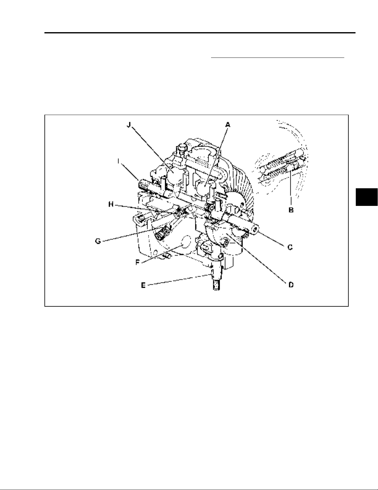
THEORY OF OPERATION
General Information
The Eaton Model 11 hydrostatic transmission, as
used on the 5xi series, is equipped with an
internal charge pressure valve, forward and
reverse check and acceleration valves, and
vibration dampening pistons. The transmission
has a splined output shaft and keyed input shaft,
both of which are supported by ball bearings.
A charge pump is located externally on the
transmission case and is driven by the input
shaft. The charge pump provides pressurized oil
to the transmission, power steering, and lift
systems.
2
Radial Ball-Piston Pump.
Acceleration Valves.
Input Shaft.
Charge Pump - Charge pressure 30-90 PSI
(2.1 - 6.2 bar). Implement lift pressure 700800 PSI (48.2 - 55.2 bar) with manual
steering, 725 PSI (50 bar) with power
steering.
5xi Series Tractor Hydraulic Service Manual 2 - 3
(E) Control Shaft - Controls transmission output speed and
direction of rotation - shaft points to the right when
installed in the 5xi transaxle.
(F) Dampening Pistons - Aids in quieter unit operation.
(G) Charge Pressure Relief Valve.
(H) Check Valve - Two used.
(I) Output Shaft.
(J) Radial Ball-Piston Motor.
Page 24
THEORY OF OPERATION
Transmission Operation
Transmission input shaft is driven at engine
speed by drive shaft. Both charge pump and
transmission pump are driven by input shaft.
Charge pump draws oil from transaxle to
“supercharge” transmission pump, make up for
normal internal leakage, and provide a cooling oil
flow. Oil travels from the outlet of the charge
pump through a hydraulic hose to the power
steering valve (on units equipped with power
steering). Then oil flows through the open-center
hydraulic lift valve and out to the oil filter adapter
through another hose. After filtering, oil passes
through a metal line and into the transmission.
NOTE: Lift valve noise is normal on manual
steering units.
7195-029
2
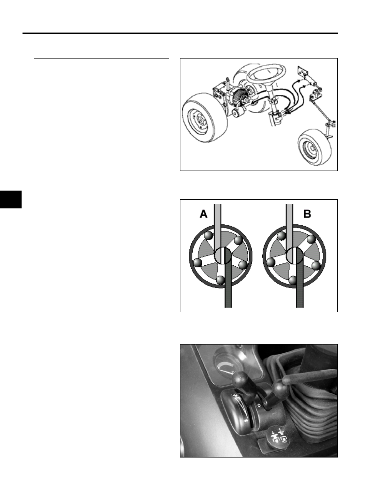
Pump section of transmission controls volume
and direction of oil flow to motor section
depending on position of motion control linkage.
As the motion control lever is moved away from
neutral position, the cam ring increases the
displacement of the pump and the flow of oil is
increased to the motor making it go faster. The
motor output shaft drives the tractor axles
through two reduction gears and a differential
assembly. Torque is generated in direct
response to load; higher pump pressure (torque)
is generated as resistance to movement
increases.
(A) Maximum Flow (B) Minimum Flow
0202-100
For optimum performance engine should be
operated at full throttle, and never less than 3/4
throttle. Under high load conditions tractor
should be slowed using traction pedal, which will
increase output torque. This is due to lower
friction and pumping losses at slower
transmission output speeds, and can be
compared to the effect of shifting a manual
transmission to a lower gear.
0202-002
2 - 4 5xi Series Tractor Hydraulic Service Manual
Page 25
THEORY OF OPERATION
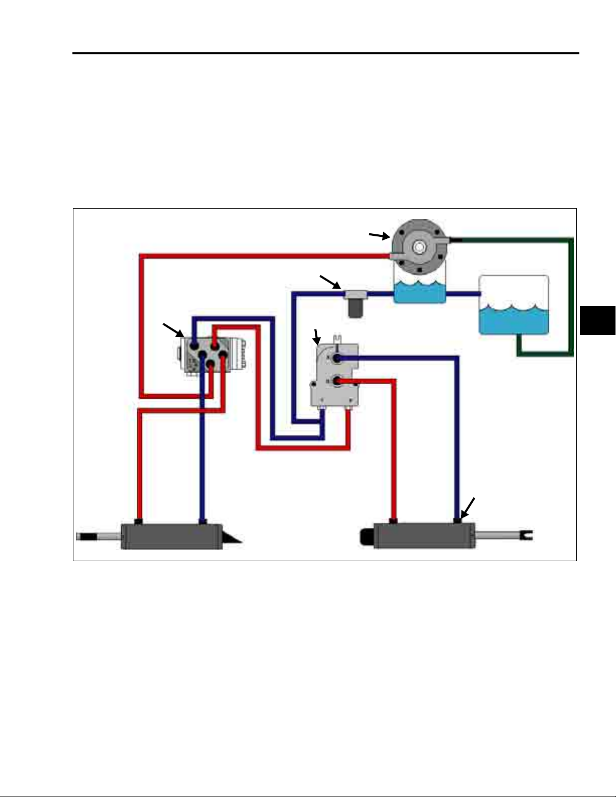
The power steering and hydraulic lift circuit are also operated by the charge pump. When the lift control valve is
moved to Raise or Lower position, the charge pump output is diverted to one of the hoses attached to the lift
cylinder. The other hose is connected through the lift valve to charge pressure hose leading to the oil filter,
permitting bleed-off of oil on that side of lift cylinder’s piston. Implement relief valve located in control valve
(manual steering) or power steering valve regulates lift system pressure at 700-800 PSI (48.2 - 55.2 bar). When
this valve opens, excess oil is bled off into the charge pressure hose leading to the oil filter.
NOTE: Lift valve noise is normal on manual steering units.
HYDROSTATIC TRANSMISSION FLOW DIAGRAM WITH POWER STEERING
A
G
H
D
C
J
B
2
I
EF
(A) Charge Pump
(B) Transaxle Sump
(C) Filter
(D) Lift Valve
(E) Lift Cylinder
(F) Steering Cylinder
(G) Power Steering Valve - With 725 PSI (50 bar) relief valve
(H) Charge Pressure Test Point: 30-90 PSI (2.1 - 6.2 bar)
(I) Lift Pressure Test Point: 725 PSI (50 bar)
5xi Series Tractor Hydraulic Service Manual 2 - 5
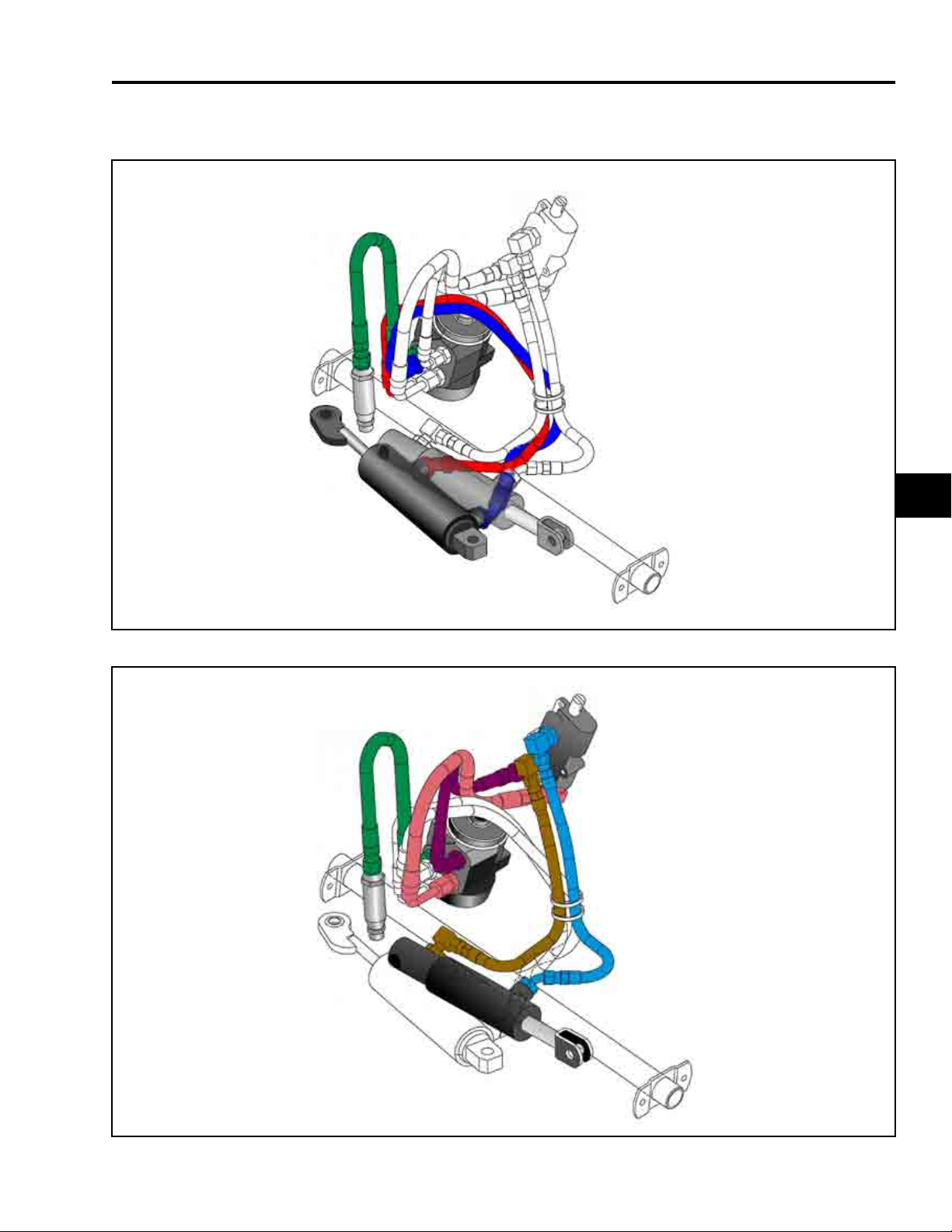
Red = Oil Under Pressure
Blue = Oil Not Under Pressure
Green = Suction Line
NOTE: Pressurization of lines at lift/steering
cylinders reverses with change in valve
actuation.
Page 26
THEORY OF OPERATION
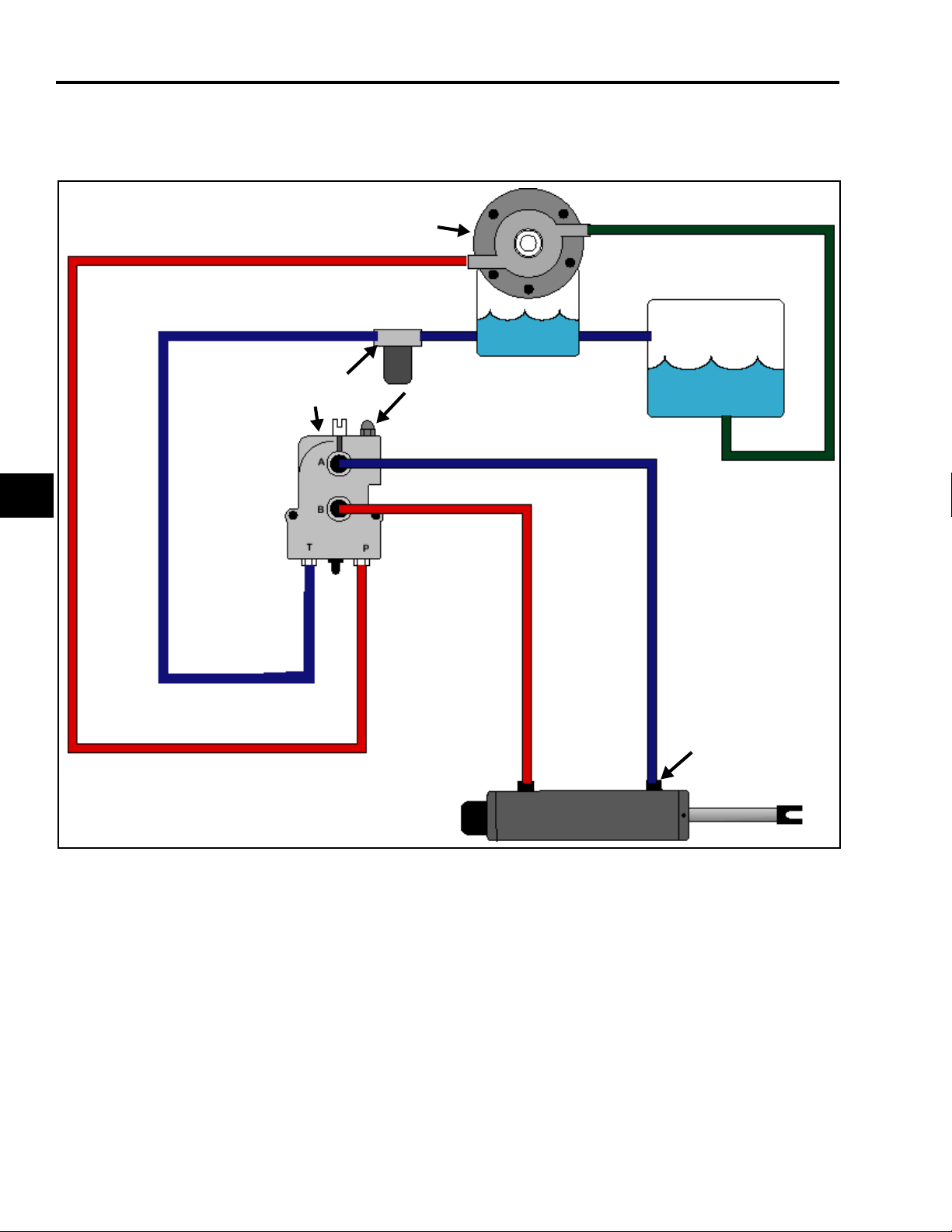
HYDROSTATIC TRANSMISSION FLOW DIAGRAM WITHOUT POWER STEERING
A
2
D
G
C
B
I
F
Illustrator Files/5xi wo ps.eps
H
E
(A) Charge Pump
(B) Transaxle Sump
(C) Filter
(D) Lift Valve
(E) Lift Cylinder
(F) Relief Valve
Setting on manual steering units 700-800 PSI (48.2 - 55.2 bar)
(G) Charge Pressure Test Point: 30-90 PSI (2.1 - 6.2 bar)
(H) Lift Pressure Test Point: 700-800 PSI (48.2 - 55.2 bar)
2 - 6 5xi Series Tractor Hydraulic Service Manual
Red = Oil Under Pressure
Blue = Oil Not Under Pressure
Green = Suction Line
NOTE: Pressurization of lines at lift/steering
cylinders reverses with change in valve
actuation. Lift valve noise is normal.
Page 27
THEORY OF OPERATION
POWER STEERING CYLINDER HYDRAULIC HOSE ROUTING
2
LIFT CYLINDER HYDRAULIC HOSE ROUTING
5xi Series Tractor Hydraulic Service Manual 2 - 7
Page 28
THEORY OF OPERATION
Flow diagrams show hydraulic circuits inside hydrostatic unit and illustrate high and low pressure areas during
operation.
Pressurized oil from the charge pump is maintained between 30 and 90 PSI (2.1 - 6.2 bar) by the charge relief
valve located inside the hydrostatic unit. When the valve opens, excess oil pressure is bled back to the transaxle
sump through a hole in the housing.
The charge pump oil enters the transmission pump section, which is turning at engine speed, and “supercharges”
it.
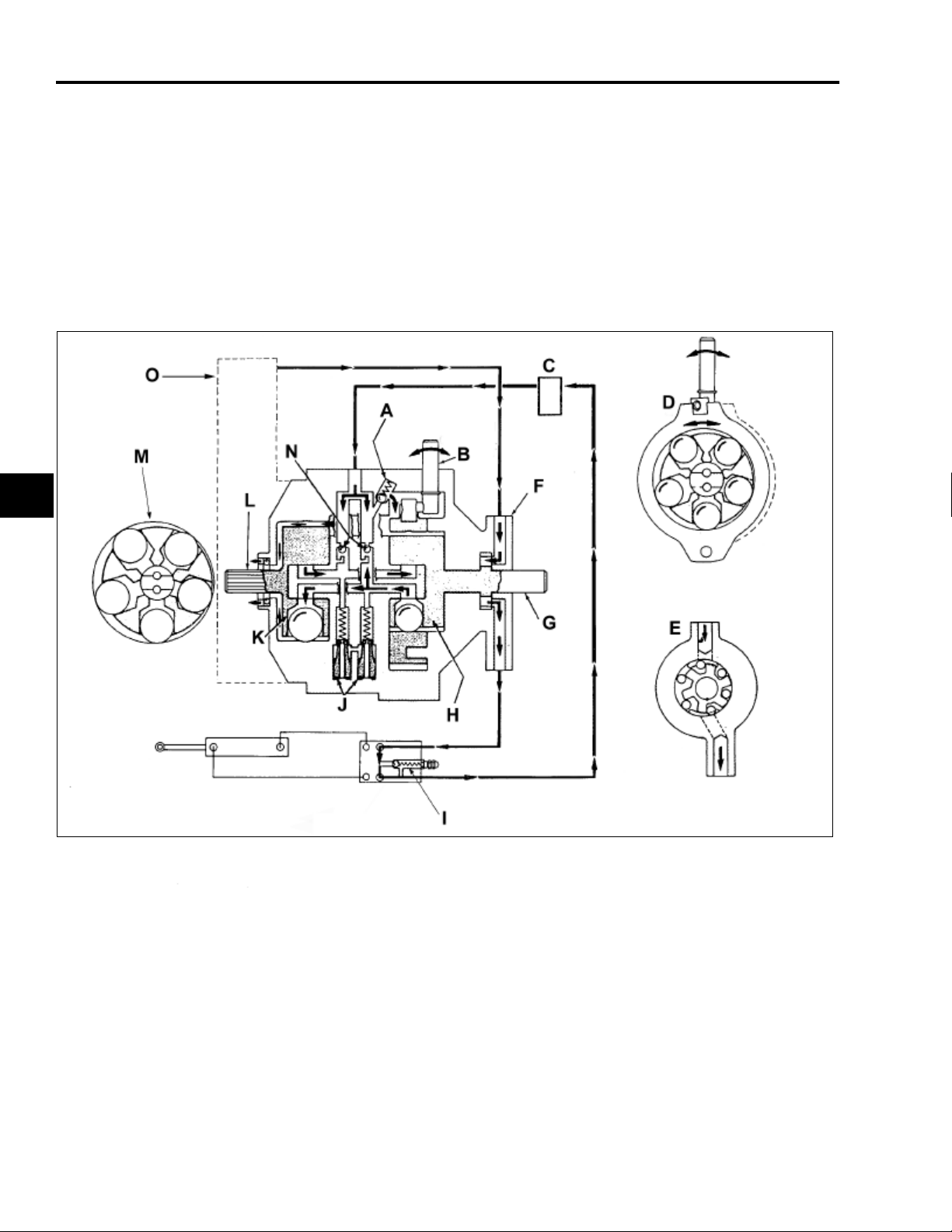
HYDROSTATIC TRANSMISSION FLOW DIAGRAM, UNITS WITHOUT POWER STEERING
2
(A) Charge Pressure Relief Valve.
(B) Motion Control Shaft.
(C) Filter.
(D) Cam Ring - Radial ball-piston hydraulic pump.
(variable displacement).
(E) Charge Pump - Transmission charge pressure 30-
90 PSI (2.1 - 6.2 bar). Implement lift system
pressure 700 PSI (48.2 bar).
(F) Charge Pump.
(G) Input Shaft.
(H) Hydraulic Pump.
2 - 8 5xi Series Tractor Hydraulic Service Manual
(I) Hydraulic Lift Control Valve - With 700 PSI (48.2
bar) relief valve.
(J) Acceleration Valves.
(K) Hydraulic Motor.
(L) Output Shaft.
(M) Radial Ball-Piston Hydraulic Motor - Fixed
Displacement.
(N) Forward/Reverse Check Valves.
(O) Transaxle Sump.
Page 29
3094-042
THEORY OF OPERATION
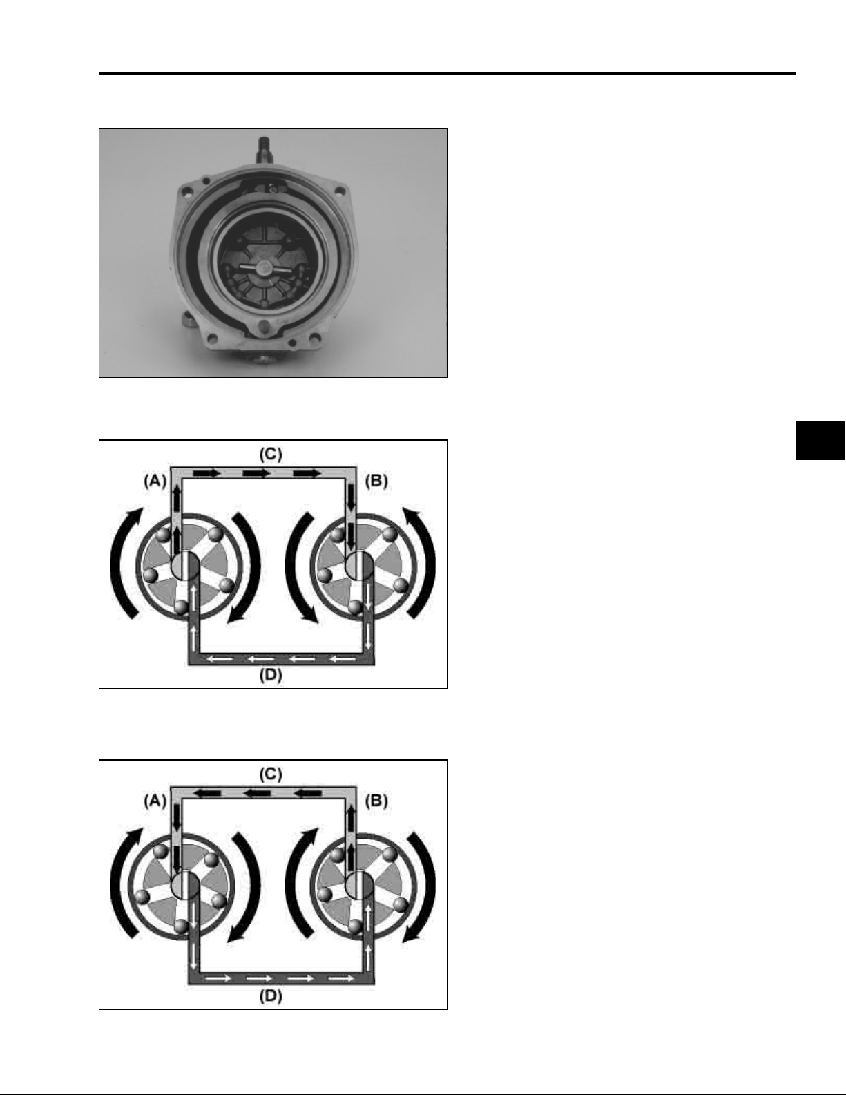
The operator controls the transmission by
moving the control shaft connected to the cam
ring within the pump. With the control shaft in
neutral, or its centered position, no flow is
generated by the pump and, therefore, the motor
portion is at rest.
When the control shaft is moved from neutral in
the “forward” direction, the cam ring in the pump
is moved off center and the pump ball-pistons
create a flow of fluid. The position of the control
shaft/cam ring is infinitely variable and any flow
rate is possible up to maximum cam ring
movement/maximum pump displacement.
0202-003
Flow created by pump moves to fixed
displacement motor through internal
passageways. Because the motor is a fixed
displacement unit, the motor requires a specific
volume of fluid for it to make one complete
revolution.
(A) Pump
(B) Motor
When the control shaft is moved from neutral to
“reverse” direction, the cam ring is swung off
center to the opposite side of the pump and the
flow from the pump is “reversed”. This flow is
directed to the other side of the motor causing its
output shaft to rotate in the opposite direction.
The pump input shaft always rotates in one
direction, dictated by the engine, while the motor
output shaft rotates in either direction, depending
on the direction of flow from the pump.
(C) High Pressure
(D) Low Pressure
2
Pump discharge flow is high pressure (dictated
by load) fluid. Flow returned from the motor to
the pump is low (or charge) pressure fluid.
(A) Pump
(B) Motor
0202-004
5xi Series Tractor Hydraulic Service Manual 2 - 9
(C) Low Pressure
(D) High Pressure
Page 30
THEORY OF OPERATION
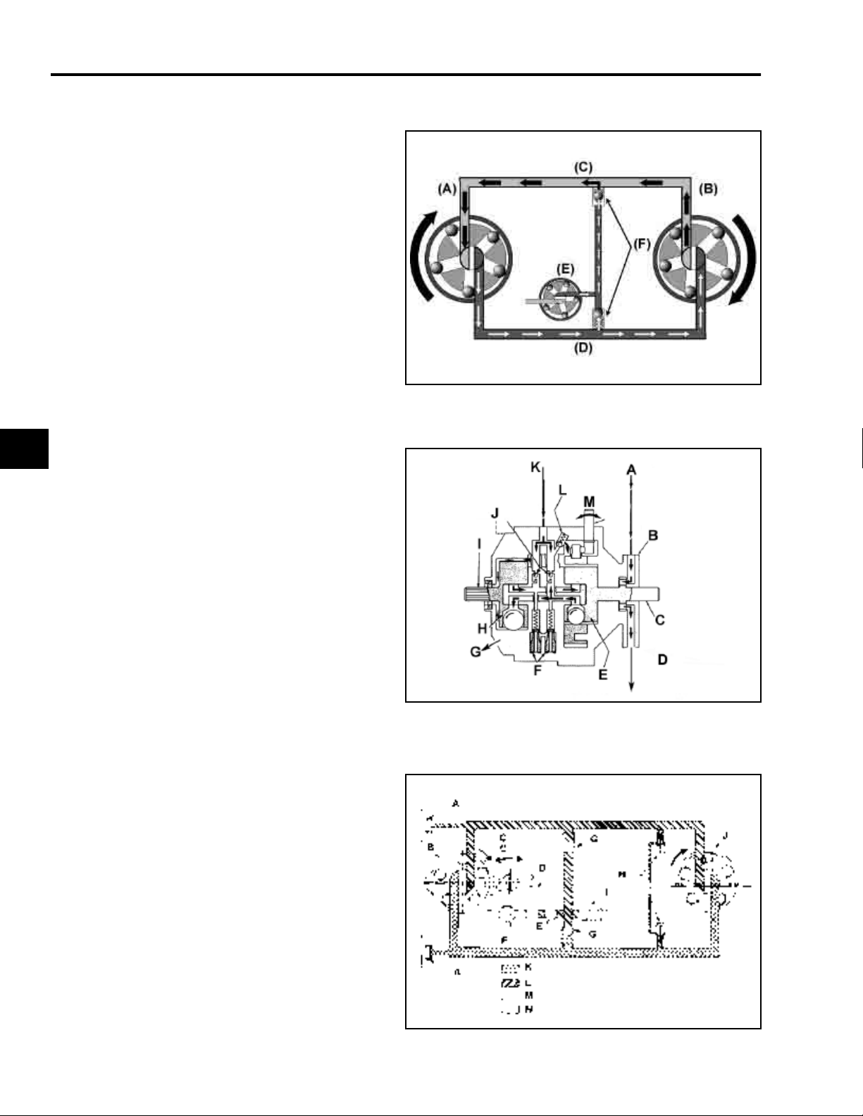
Due to internal leakage, fluid being returned to
the inlet side of the pump from the exhaust side
of the motor is less than required by the pump.
To replace this needed fluid, check valves are
located in each side of closed loop. The check
valve located on the low pressure side of the
pump will open allowing fluid to enter loop, from
the charge pump circuit, to make up leakage
losses.
(A) Pump
(B) Motor
(C) Low Pressure
(D) High Pressure
(E) Charge Pump
(F) Check Valves
0202-005
2
Internal acceleration valves are used in both
forward and reverse directions. These valves
are spring loaded to close “slowly” as pressure
(load) increases. These valves control the rate
of acceleration of the motor output shaft, assist in
providing a positive neutral, and permit hand
pushing the tractor without operating the engine.
(A) From Sump
(B) Charge Pump
(C) Input Shaft
(D) To Lift
(E) Hydraulic Pump
(F) Acceleration
Valves
(G) To Sump
(H) Hydraulic Motor
(I) Output Shaft
(J) Forward/Reverse
Check Valves
(K) From Lift
(L) Charge Pressure
Relief Valve
(M) Motion Control Shaft
In operation, as the tractor’s motion control lever
is moved out of neutral, the appropriate
acceleration valve bleeds off some of the high
pressure oil before it closes. This initial
temporary pressure reduction results in
smoother tractor acceleration from a standstill.
(A) Dampening Piston
(B) Pump
(C) Control Shaft
(D) Aux. Hyd. Valve
(E) Filter
(F) Charge Pump
(G) Check Valve
(H) Acceleration
Valves
(I) Charge Relief
Valve
(J) Motor
(K) High Pressure
(L) Low Pressure (30-90
PSI)
(M) Transaxle Sump
(N) Lift System Pressure
(700 PSI (48 bar) with
manual steering; 725
PSI (50 bar) with
power steering
0202-006
0202-007
2 - 10 5xi Series Tractor Hydraulic Service Manual
Page 31

0202-007
THEORY OF OPERATION
Model 11 has two dampening pistons (A), which
rest against the cam ring and are controlled by
system pressure. In operation, they reduce
control shaft vibration and transmission noise.
2
5xi Series Tractor Hydraulic Service Manual 2 - 11
Page 32

THIS PAGE INTENTIONALLY LEFT BLANK
2 - 12 5xi Series Tractor Hydraulic Service Manual
Page 33

QUICK REFERENCE SECTION
TROUBLESHOOTING
Safety Information . . . . . . . . . . . . . . . . . . . . . . . . . . . . . . . . . . . . . . . . . . . . . . .
Specifications. . . . . . . . . . . . . . . . . . . . . . . . . . . . . . . . . . . . . . . . . . . . . . . . . . .
Maintenance . . . . . . . . . . . . . . . . . . . . . . . . . . . . . . . . . . . . . . . . . . . . . . . . . . .
TROUBLESHOOTING
Theory of Operation. . . . . . . . . . . . . . . . . . . . . . . . . . . . . . . . . . . . . . . . . . . . . .
Troubleshooting Tables . . . . . . . . . . . . . . . . . . . . . . . . . . . . . . . . . . . . . . . . .
Troubleshooting Flow Charts. . . . . . . . . . . . . . . . . . . . . . . . . . . . . . . . . . . . . . .
Hydraulic Systems Testing . . . . . . . . . . . . . . . . . . . . . . . . . . . . . . . . . . . . . . . .
1a
1b
1c
2
3
4
5
REPAIR PROCEDURES
Chassis . . . . . . . . . . . . . . . . . . . . . . . . . . . . . . . . . . . . . . . . . . . . . . . . . . . . . . .
Hydrostatic Drive . . . . . . . . . . . . . . . . . . . . . . . . . . . . . . . . . . . . . . . . . . . . . . . .
Hydraulic Systems. . . . . . . . . . . . . . . . . . . . . . . . . . . . . . . . . . . . . . . . . . . . . . .
5xi Series Tractor Hydraulic Service Manual 3 - 1
6
7
8
Page 34

TROUBLESHOOTING
Tractor will not operate in either direction; engine bogs down or stalls. . . . . . . . . 3 - 3
Tractor goes forward only at partial speed and is slow or
does not operate in reverse. . . . . . . . . . . . . . . . . . . . . . . . . . . . . . . . . . . . . . . 3 - 3
Tractor will not operate in either direction. . . . . . . . . . . . . . . . . . . . . . . . . . . . . . . 3 - 3
Tractor operates erratically. . . . . . . . . . . . . . . . . . . . . . . . . . . . . . . . . . . . . . . . . . 3 - 4
Tractor operates in both directions but with loss of power and
condition becomes worse as transmission becomes hot. . . . . . . . . . . . . . . . 3 - 4
Transmission overheating. . . . . . . . . . . . . . . . . . . . . . . . . . . . . . . . . . . . . . . . . . . 3 - 4
Table of Contents
3
Abnormal vibration or noise. . . . . . . . . . . . . . . . . . . . . . . . . . . . . . . . . . . . . . . . . 3 - 4
Hydraulic lift system does not operate or does not operate properly,
but tractor operates normally. . . . . . . . . . . . . . . . . . . . . . . . . . . . . . . . . . . . . . 3 - 5
Oil is leaking out high-low shift fork hole during operation. . . . . . . . . . . . . . . . . . 3 - 5
3 - 2 5xi Series Tractor Hydraulic Service Manual
Page 35

TROUBLESHOOTING
Whenever a problem occurs with the hydrostatic drive system, you should always check these
items first:
1. Transmission oil is at proper level and air is bled from system.
2. Make sure the High-Low speed lever is not in neutral.
3. Speed control linkage functions properly.
4. Cruise control is turned off.
Tractor will not operate in either direction; engine bogs down or stalls.
Possible Cause Corrective Action
Low transmission oil level Fill to full “F” mark on dipstick (when trans. is cold)
Motion control linkage Adjust, repair, or replace
The brake is sticking Repair linkage; replace brake assembly
Brake adjustment is too tight Adjust the brake
Tractor goes forward only at partial speed and is slow or does not operate in
reverse.
Possible Cause Corrective Action
The cruise control was engaged when the High-Low
range lever was in “N”.
The engine is running at partial speed Move the throttle to “FAST”
The linkage is out of adjustment Verify full motion is obtained on motion control shaft.
Smart Turn™ steering out of adjustment Adjust if necessary
There is internal hydro wear Repair/replace transmission
Turn the cruise control off
Adjust if necessary.
Tractor will not operate in either direction.
Possible Cause Corrective Action
The transmission oil is low Fill to full “F” mark on transmission oil dipstick when
transmission is cold
The power steering filter is dirty Clean power steering filter
The control linkage needs adjustment or replacement Adjust, repair, or replace
3
The parking brake was not released or the parking
brake is not releasing
The drive shaft or wheel hub key has sheared Replace
Faulty transmission/transaxle Repair/replace transmission/transaxle
5xi Series Tractor Hydraulic Service Manual 3 - 3
Release the parking brake or check the linkage
Page 36

TROUBLESHOOTING
Tractor operates erratically.
Possible Cause Corrective Action
The transmission control linkage needs adjustment or
replacement
The transmission oil level is low Fill to the full “F” mark on the transmission dipstick
The transmission is faulty Repair/replace
Adjust, repair, or replace
when transmission is cold
Tractor operates in both directions but with loss of power and
condition becomes worse as transmission becomes hot.
Possible Cause Corrective Action
The transmission oil level is low Fill to the full “F” mark on the transmission dipstick
when transmission is cold
The transmission shows signs of overheating or water
contamination
3
The cooling fan and/or transmission cooling fins are
faulty or dirty
The engine is not operating at full throttle Increase the engine speed to full throttle
The power steering filter is dirty Clean the power steering filter
Replace the transmission oil and filter
Clean the transmission and/or replace the fan
Transmission overheating.
Possible Cause Corrective Action
Not operating engine at full throttle Increase engine speed to full throttle
Low oil level Fill to full “F” mark on dipstick (when trans. is cold)
Accumulation of dirt and debris on hydrostatic trans. Clean
Loose fan or broken blades Repair or replace
Abnormal vibration or noise.
Possible Cause Corrective Action
The engine mounting bolts are loose Tighten the engine mounting bolts
The idler pulley or cutter deck blade is loose Tighten the appropriate pulley
The transaxle cooling fan is loose Repair or replace as necessary
There is a problem with the electric clutch Repair or replace as necessary
Drive shaft/couplings Repair or replace as necessary
3 - 4 5xi Series Tractor Hydraulic Service Manual
Page 37

TROUBLESHOOTING
Hydraulic lift system does not operate or does not operate properly, but
tractor operates normally.
Possible Cause Corrective Action
Oil level is low Fill to proper level
Faulty control valve* Repair or replace
Restricted, plugged, or leaking hoses or fittings Repair or replace
Low charge pump pressure Check pressure
Faulty lift cylinder Repair or replace cylinder
Oil is leaking out high-low shift fork hole during operation.
Possible Cause Corrective Action
Dipstick vent hole plugged Repair or replace dipstick
* Noise is normal on manual steering tractors.
3
5xi Series Tractor Hydraulic Service Manual 3 - 5
Page 38

THIS PAGE INTENTIONALLY LEFT BLANK
3 - 6 5xi Series Tractor Hydraulic Service Manual
Page 39

QUICK REFERENCE SECTION
TROUBLESHOOTING
Safety Information . . . . . . . . . . . . . . . . . . . . . . . . . . . . . . . . . . . . . . . . . . . . . . .
Specifications. . . . . . . . . . . . . . . . . . . . . . . . . . . . . . . . . . . . . . . . . . . . . . . . . . .
Maintenance . . . . . . . . . . . . . . . . . . . . . . . . . . . . . . . . . . . . . . . . . . . . . . . . . . .
TROUBLESHOOTING
Theory of Operation. . . . . . . . . . . . . . . . . . . . . . . . . . . . . . . . . . . . . . . . . . . . . .
Troubleshooting Tables. . . . . . . . . . . . . . . . . . . . . . . . . . . . . . . . . . . . . . . . . . .
Troubleshooting Flow Charts. . . . . . . . . . . . . . . . . . . . . . . . . . . . . . . . . . . . .
Hydraulic Systems Testing . . . . . . . . . . . . . . . . . . . . . . . . . . . . . . . . . . . . . . . .
1a
1b
1c
2
3
4
5
REPAIR PROCEDURES
Chassis . . . . . . . . . . . . . . . . . . . . . . . . . . . . . . . . . . . . . . . . . . . . . . . . . . . . . . .
Hydrostatic Drive . . . . . . . . . . . . . . . . . . . . . . . . . . . . . . . . . . . . . . . . . . . . . . . .
Hydraulic Systems. . . . . . . . . . . . . . . . . . . . . . . . . . . . . . . . . . . . . . . . . . . . . . .
5xi Series Tractor Hydraulic Service Manual 4 - 1
6
7
8
Page 40

TROUBLESHOOTING
Tractor Will Not Operate In Either Direction . . . . . . . . . . . . . . . . . . . . . . . . . . . . . 4 - 3
Tractor Operates In Both Directions, But Loses Power As Oil Becomes Hot and/or
Transmission Overheats . . . . . . . . . . . . . . . . . . . . . . . . . . . . . . . . . . . . . . . . . 4 - 4
Tractor Does Not Return To Neutral . . . . . . . . . . . . . . . . . . . . . . . . . . . . . . . . . . 4 - 5
Tractor Operates Normally In One Direction,
But Is Very Slow in Opposite Direction . . . . . . . . . . . . . . . . . . . . . . . . . . . . . . 4 - 5
Tractor Operates In Only One Direction . . . . . . . . . . . . . . . . . . . . . . . . . . . . . . . . 4 - 5
Tractor Operates Erratically . . . . . . . . . . . . . . . . . . . . . . . . . . . . . . . . . . . . . . . . . 4 - 5
Table of Contents
4
Hydraulic Lift System Does Not Operate, Or Does Not
Operate Properly; Tractor Operates Normally . . . . . . . . . . . . . . . . . . . . . . . . 4 - 6
4 - 2 5xi Series Tractor Hydraulic Service Manual
Page 41

OK
TRACTOR WILL NOT OPERATE IN EITHER DIRECTION
TROUBLESHOOTING
NOTE:
IF THE HYDRAULIC LIFT SYSTEM OPERATES NORMALLY THE
TRANSMISSION CHARGE PUMP IS WORKING.
CHECK THAT SPEED SELECTOR IS NOT IN NEUTRAL
CHECK OIL LEVEL
LOW FAULTY FAULTY
FILL TO
PROPER LEVEL
CHECK CHARGE
PRESSURE
LOW
OK OK
CLEAN, LUBRICATE, ADJUST,
OK
CHECK MOTION
CONTROL LINKAGE
REPAIR, OR REPLACE
OK
REPAIR/REPLACE HYDROSTATIC
TRANSMISSION
Possible Defects:
Acceleration Valve
Stuck Open
Both Check Valves
Stuck Open
High Internal Leakage Due to
Wear/Contamination
Mechanical Failure
CHECK INPUT DRIVE &
TRANSAXLE
REPAIR OR
REPLACE
4
INSPECT FITTINGS, LINES,
HOSES, HYDRAULIC LIFT
VALVE FOR BLOCKAGE
FAULTY
REPAIR OR
REPLACE
5xi Series Tractor Hydraulic Service Manual 4 - 3
OK OK
CLOGGED
INSPECT
OIL FILTER AND
POWER STEERING
SCREEN
REPLACE
REPAIR/REPLACE
HYDROSTATIC
TRANSMISSION
Possible Defects:
Charge Relief
Valve Stuck Open
Faulty Charge Pump
High Internal
Leakage Due to
Wear/Contamination
Mechanical Failure
Page 42

TROUBLESHOOTING
TRACTOR OPERATES IN BOTH DIRECTIONS, BUT LOSES
POWER AS OIL BECOMES HOT
TRANSMISSION OVERHEATS
4
CHECK OIL
LEVEL
LOW
FILL TO
PROPER LEVEL
CHECK CHARGE
PRESSURE
LOW
INSPECT FITTINGS, LINES,
HOSES, HYDRAULIC LIFT
VALVE, & POWER STEERING
SCREEN FOR PARTIAL
BLOCKAGE
FAULTY
REPAIR OR
REPLACE
OK
SIGNS OF
OVERHEATING
OR WATER
OK
CHECK OIL
CONDITION
REPLACE OIL
AND FILTER
MAKE SYSTEM
PERFORMANCE TEST
TO CONFIRM LOW
POWER CONDITION
OK
CLOGGED
OK OK
INSPECT
OIL FILTER
REPLACE
CHECK COOLING
FAN & TRANS.
COOLING FINS
FAULTY
DIRTY
REPLACE FAN
CLEAN TRANS.
OK
OK
CHECK
APPLICATION
TRACTOR
OVERLOADED
MAINTAIN FULL
ENGINE RPM,
REDUCE SPEED,
AND LOAD
REPAIR/ REPLACE
HYDROSTATIC
TRANSMISSION
Probable Defect:
High Internal
Leakage Due to
Wear/Contamination
REPAIR/ REPLACE
HYDROSTATIC
TRANSMISSION
Possible Defects:
Charge Relief Valve
Leaking
Faulty Charge Pump
Internal Leakage
Due to Wear/Contamination
4 - 4 5xi Series Tractor Hydraulic Service Manual
Page 43

TROUBLESHOOTING
TRACTOR DOES NOT RETURN TO NEUTRAL.
TRACTOR OPERATES NORMALLY IN ONE DIRECTION,
BUT IS VERY SLOW IN OPPOSITE DIRECTION.
TRACTOR OPERATES IN ONLY ONE DIRECTION.
CHECK MOTION
CONTROL LINKAGE
FAULTY
CLEAN, LUBRICATE,
ADJUST, REPAIR,
OR REPLACE
OK
NEUTRAL
ADJUSTMENT
INCORRECT
NEUTRAL
TRACTOR OPERATES ERRATICALLY
CHECK MOTION
CONTROL LINKAGE
FAULTY FAULTY
CLEAN, LUBRIDATE,
ADJUST, REPAIR,
OR REPLACE
OK
CHECK INPUT
DRIVE & TRANSAXLE
OR REPLACE
CHECK
RESET
REPAIR
OK
OK
REPAIR/REPLACE
HYDROSTATIC
TRANSMISSION
Possible Defects:
One Check Valve
Stuck Open
Mechanical Failure
4
REPAIR/REPLACE
HYDROSTATIC
TRANSMISSION
Possible Defects:
Check Valve or
Acceleration
Valves Sticking
Periodically
Acceleration Valve
Closing too Slowly
5xi Series Tractor Hydraulic Service Manual 4 - 5
Page 44

TROUBLESHOOTING
HYDRAULIC LIFT SYSTEM DOES NOT OPERATE,
OR DOES NOT OPERATE PROPERLY;
TRACTOR OPERATES NORMALLY.
4
CHECK OIL
LEVEL
LOW
FILL TO
PROPER LEVEL
INSPECT FITTINGS,
LINES, HOSES,
HYDRAULIC LIFT
VALVE, AND POWER
STEERING SCREEN
FOR PARTIAL
BLOCKAGE
INSPECT
OK
CONTROL VALVE,
CYLINDER, AND
HOSES
FAULTY
REPAIR OR
REPLACE
OK OK
CLOGGED
INSPECT
OIL FILTER
CHECK
OK OK
IMPLEMENT
LIFT SYSTEM
PRESSURE
LOW
CHECK CHARGE
PRESSURE
LOW
REPAIR/REPLACE
HYDROSTATIC
TRANSMISSION
Possible Defect:
Charge Pump Can
Not Develop Full
Output
OK
REPAIR
OR
REPLACE
LIFT CYLINDER
REPAIR OR
REPLACE
CONTROL VALVE
CHECK IMPLEMENT
LIFT SYSTEM
PRESSURE
LOW
FAULTY
REPAIR OR
REPLACE
4 - 6 5xi Series Tractor Hydraulic Service Manual
REPLACE
Page 45

QUICK REFERENCE SECTION
HYDRAULIC SYSTEMS TESTING
Safety Information . . . . . . . . . . . . . . . . . . . . . . . . . . . . . . . . . . . . . . . . . . . . . . .
Specifications. . . . . . . . . . . . . . . . . . . . . . . . . . . . . . . . . . . . . . . . . . . . . . . . . . .
Maintenance . . . . . . . . . . . . . . . . . . . . . . . . . . . . . . . . . . . . . . . . . . . . . . . . . . .
TROUBLESHOOTING
Theory of Operation. . . . . . . . . . . . . . . . . . . . . . . . . . . . . . . . . . . . . . . . . . . . . .
Troubleshooting Tables. . . . . . . . . . . . . . . . . . . . . . . . . . . . . . . . . . . . . . . . . . .
Troubleshooting Flow Charts. . . . . . . . . . . . . . . . . . . . . . . . . . . . . . . . . . . . . . .
Hydraulic Systems Testing. . . . . . . . . . . . . . . . . . . . . . . . . . . . . . . . . . . . . . .
1a
1b
1c
2
3
4
5
REPAIR PROCEDURES
Chassis . . . . . . . . . . . . . . . . . . . . . . . . . . . . . . . . . . . . . . . . . . . . . . . . . . . . . . .
Hydrostatic Drive . . . . . . . . . . . . . . . . . . . . . . . . . . . . . . . . . . . . . . . . . . . . . . . .
Hydraulic Systems. . . . . . . . . . . . . . . . . . . . . . . . . . . . . . . . . . . . . . . . . . . . . . .
5 - 1 5xi Series Tractor Hydraulic Service Manual
6
7
8
Page 46

TROUBLESHOOTING
Testing System Performance . . . . . . . . . . . . . . . . . . . . . . . . . . . . . . . . . . . . . . . . 5 - 3
Pressure Checks . . . . . . . . . . . . . . . . . . . . . . . . . . . . . . . . . . . . . . . . . . . . . . . . . 5 - 4
Lift System Pressure . . . . . . . . . . . . . . . . . . . . . . . . . . . . . . . . . . . . . . . . . . . . . . 5 - 4
Charge Pressure . . . . . . . . . . . . . . . . . . . . . . . . . . . . . . . . . . . . . . . . . . . . . . . . . 5 - 5
Table of Contents
5
5 - 2 5xi Series Tractor Hydraulic Service Manual
Page 47

1116-01
HYDRAULIC SYSTEMS TESTING
Testing System Performance
A test for observing transmission system
performance under load can be helpful when
checking a “low power”, or “tractor loses power”
condition.
1. Operate tractor to bring engine and drive
train to normal operating temperature.
2. Anchor rear of tractor to an immovable
object (tree, beam, etc.) with a chain secured
to transaxle case. Rear wheels must be on a
high friction surface, such as unfinished
concrete or asphalt. Front wheels may be
placed against a curb or wall as an
alternative, but provision must be made to
keep front of tractor on ground.
3. With transaxle in high range, set engine at
half throttle and move the motion control
pedal fully forward. The tractor should have
enough power to spin the rear wheels with
an operator in seat.
0202-002
4. If the wheels do not spin, carefully note
transmission/transaxle performance to
isolate the problem.
5. If the test results are marginal, the tractor
should be used under actual operating
conditions to isolate the problem.
5
3653-005
5xi Series Tractor Hydraulic Service Manual 5 - 3
Page 48

HYDRAULIC SYSTEMS TESTING
Pressure Checks
When performing hydraulic system pressure
checks do not connect a pressure gauge in a
way that cuts off flow to the hydraulic valve
(manual steering) or power steering valve, which
eliminates the pressure relief valve from the
system. Charge pump pressure will build until
internal failure occurs.
A suggested gauge system is illustrated.
(A) Gauge 0 - 1000 PSI (0 - 700 bar)
(B) T fitting 1/4 NPT (brass or steel)
(C) Flat face to 1/4 NPT fitting
(D) Replacement hydraulic hose
1118-04
Lift System Pressure
1. Connect the gauge system to the front lift
cylinder hose. The gauge can be connected
to place the hydraulic lift cylinder either in or
out of the circuit, as desired.
5
NOTE: Lift system pressure relief valve is part of
lift control valve on manual steering models and
power steering valve on power steering models.
Noise from the control valve for manual steering
tractors is normal.
1118-01
2. With the engine running, hold the lift control
valve in “Down” direction. Normal pressure
reading is 700-800 PSI (48.2 - 55.2 bar) for
manual steering models, and 725 PSI (50
bar) for power steering models. If pressure
is not to specification, replace the hydraulic
lift control valve on manual steering units or
the power steering valve on power steering
units. Do not attempt adjustment of the
relief valve.
Refer to appropriate Troubleshooting Chart
for troubleshooting procedure.
0202-008
5 - 4 5xi Series Tractor Hydraulic Service Manual
Page 49

1118-03
HYDRAULIC SYSTEMS TESTING
Charge Pressure
1. Remove the pipe plug and connect gauge
directly to filter base. Although thread is
¼-18 NPT, it will accept ½-20 SAE fitting for
test purposes.
2. Operate engine. Normal charge pressure is
30 - 90 PSI (2.1 - 6.2 bar). Refer to
appropriate Troubleshooting Chart for
troubleshooting procedures.
1118-02
NOTE: Always check implement lift pressure
relief valve for signs of tampering if charge
pressure is low. A relief valve set too high will
cause permanent internal damage to charge
pump and hydrostatic transmission. If damage
has occurred, repair or replace transmission -do not operate lift system until hydraulic lift
control valve has been replaced or relief valve
returned to original setting. The manual steering
relief valve is not intended to be adjustable.
5
5xi Series Tractor Hydraulic Service Manual 5 - 5
Page 50

THIS PAGE INTENTIONALLY LEFT BLANK
5 - 6 5xi Series Tractor Hydraulic Service Manual
Page 51

QUICK REFERENCE SECTION
CHASSIS
Safety Information . . . . . . . . . . . . . . . . . . . . . . . . . . . . . . . . . . . . . . . . . . . . . . .
Specifications. . . . . . . . . . . . . . . . . . . . . . . . . . . . . . . . . . . . . . . . . . . . . . . . . . .
Maintenance . . . . . . . . . . . . . . . . . . . . . . . . . . . . . . . . . . . . . . . . . . . . . . . . . . .
TROUBLESHOOTING
Theory of Operation. . . . . . . . . . . . . . . . . . . . . . . . . . . . . . . . . . . . . . . . . . . . . .
Troubleshooting Tables. . . . . . . . . . . . . . . . . . . . . . . . . . . . . . . . . . . . . . . . . . .
Troubleshooting Flow Charts. . . . . . . . . . . . . . . . . . . . . . . . . . . . . . . . . . . . . . .
Hydraulic Systems Testing . . . . . . . . . . . . . . . . . . . . . . . . . . . . . . . . . . . . . . . .
1a
1b
1c
2
3
4
5
REPAIR PROCEDURES
Chassis. . . . . . . . . . . . . . . . . . . . . . . . . . . . . . . . . . . . . . . . . . . . . . . . . . . . . . .
Hydrostatic Drive . . . . . . . . . . . . . . . . . . . . . . . . . . . . . . . . . . . . . . . . . . . . . . . .
Hydraulic Systems. . . . . . . . . . . . . . . . . . . . . . . . . . . . . . . . . . . . . . . . . . . . . . .
5xi Series Tractor Hydraulic Service Manual 6 - 1
6
7
8
Page 52

CHASSIS
REAR FENDERS, FOOTRESTS, & TUNNEL
TRANSAXLE R & R
Table of Contents
General Information . . . . . . . . . . . . . . . . . . . . . . . . . . . . . . . . . . . . . . . . . . . . 6 - 3
Removal . . . . . . . . . . . . . . . . . . . . . . . . . . . . . . . . . . . . . . . . . . . . . . . . . . . . . 6 - 3
Reassembly . . . . . . . . . . . . . . . . . . . . . . . . . . . . . . . . . . . . . . . . . . . . . . . . . 6 - 13
Smart Turn™ Linkage Adjustments . . . . . . . . . . . . . . . . . . . . . . . . . . . . . . . 6 - 22
6
6 - 2 5xi Series Tractor Hydraulic Service Manual
Page 53

0109-039
CHASSIS
REAR FENDERS, FOOTRESTS, & TUNNEL
General Information
The seat, rear fenders, footrests, and tunnel can
be removed as a unit providing easy access to
chassis components.
Removal
1. Disconnect the electrical connections for the
seat switch, cruise control, and taillights (as
applicable) from the wiring harness.
0109-021
NOTE: The cruise control and taillights
share the same connector, which is located
under the right fender.
6
2. Remove the brake and motion control
pedals.
0109-003/0109-020
5xi Series Tractor Hydraulic Service Manual 6 - 3
Page 54

CHASSIS
3. Remove the four bolts securing the fender to
the frame (two on each side of the seat).
4. Remove the nuts from the front footrest
supports and the clamps from the rear
supports.
0109-004
0109-019
6
5. Remove the three air intake screens.
0109-015
6 - 4 5xi Series Tractor Hydraulic Service Manual
Page 55

0109-017
CHASSIS
6. Remove the knob for the transaxle range
selector.
7. With the help of an assistant, lift the rear of
the fender assembly until it clears the
transaxle shift lever. Then remove the
assembly to the rear of the tractor.
0109-014
CAUTION: Do not dislodge the fuel tank
from the mount. If there is fuel in the tank, it
will be unbalanced and can tip.
6
Remove wiring for the fuel gauge sender (white
rheostat, black ground).
3031-03
5xi Series Tractor Hydraulic Service Manual 6 - 5
Page 56

CHASSIS
On diesel powered units, disconnect the fuel
return line (A). Remove the vent line from the
bracket (B), then remove the bracket.
Close the fuel shut off valve, remove the supply
line from the valve.
3031-13
3606-003
6
Lift the fuel tank from the mounting bracket.
PHOTO OF NEW TANK
3606-005
6 - 6 5xi Series Tractor Hydraulic Service Manual
Page 57

3606-008
CHASSIS
TRANSAXLE R & R
Clean area around dipstick, then remove the
dipstick tube from the axle and cover the hole
with tape to prevent dirt from entering the
transmission.
Remove the link (A) connecting the lower
steering plate to the bell crank (B).
3606-012
Unplug the safety switch.
3031-06
5xi Series Tractor Hydraulic Service Manual 6 - 7
6
Page 58

CHASSIS
Remove the hydraulic line from the power
steering valve.
Hold the 45° fitting in position while removing the
hydraulic line.
To remove the 45° fitting from the charge pump,
loosen the jam nut and remove the fitting,
washer, and O-ring.
3606-046
0202-009
6
Disconnect the drive shaft from the transmission
input yoke.
0202-010
6 - 8 5xi Series Tractor Hydraulic Service Manual
Page 59

3606-020
CHASSIS
Remove brake rod by first removing the adjusting
nut and spring.
Then remove the cotter pin and washer from the
other end of the rod at the brake pivot plate.
0202-011
Remove the rod by pulling it forward.
3606-031
5xi Series Tractor Hydraulic Service Manual 6 - 9
6
Page 60

CHASSIS
Remove the two 1/4” bolts securing the guard
below the transmission cooling fan and remove
the guard.
Remove the two carriage bolts securing the rear
transaxle brace to the frame rails.
3606-029
3606-038
6
Remove the frame crossmember/tank mount.
3606-043
6 - 10 5xi Series Tractor Hydraulic Service Manual
Page 61

0202-12
CHASSIS
Place a floor jack under the transaxle, raise the
rear of the tractor and support the frame with
safety stands.
Support the transaxle with a floor jack. Remove
the five 3/8” bolts attaching the transaxle to the
frame.
0202-013/0202-014
Lower the transaxle until the Smart Turn™
Steering (A) clears the range selector pivot (B).
3606-072
5xi Series Tractor Hydraulic Service Manual 6 - 11
6
Page 62

CHASSIS
Remove the transaxle assembly from the frame
rails by carefully lowering it while rolling it out
from the rear of the tractor.
To remove the Smart Turn™ Steering
mechanism, first loosen the nut securing the
control lever to the tapered shaft one turn.
3606-05-c
3606-060
6
Wedge a large straight blade screwdriver behind
the control lever. Then tap the retaining nut
sharply to separate the control lever from the
shaft.
3606-062
6 - 12 5xi Series Tractor Hydraulic Service Manual
Page 63

3606-068
CHASSIS
Remove the nut from the control shaft along with
the three bolts securing the Smart Turn™
Steering assembly to the transaxle.
Reassembly
When installing the Smart Turn™ steering
assembly, first slide the plastic locator plate over
the speed control shaft on the hydrostatic
transmission.
0202-015
(A) Plastic Locator Plate
(B) Speed Control Shaft
6
Install the Smart Turn™ steering so that the
buttons (A) on the plastic locator plate are fully
seated in the holes in the Smart Turn™ steering
control plate.
0202-016
5xi Series Tractor Hydraulic Service Manual 6 - 13
Page 64

CHASSIS
Install Smart Turn™ Steering assembly on
transaxle. Wire the actuating rod up to assist in
properly locating it in the chassis.
Place transaxle on floor jack and carefully slide it
between the frame rails keeping it low enough so
that the Smart Turn™ Steering assembly (A)
clears the range selector crossbar (B).
3606-065
0202-017
6
When the Smart Turn™ Steering assembly is
clear of the range selector raise the transaxle
into position between the frame rails while
guiding the Smart Turn™ Steering link (A) above
the pivot (B).
0202-018
6 - 14 5xi Series Tractor Hydraulic Service Manual
Page 65

0202-019
CHASSIS
Guide the drive shaft bolts through the spacers in
the rubber coupling.
As the transaxle moves into place make sure the
range selector pin is properly located in the shift
fork.
3031-06
NOTE: If oil is being forced out through HighLow shift fork hole during operation, the air vent
in dipstick is plugged.
6
Install the five 3/8” mounting bolts and torque to
27-33 ft·lb. (37.8 - 46.2 N·m).
0202-013/0202-014
5xi Series Tractor Hydraulic Service Manual 6 - 15
Page 66

CHASSIS
Install the rear frame crossmember/fuel tank
mount.
Install the brake rod from the pivot to the brake
band.
3606-041
3606-020
6
Adjust the brake by turning the adjustment nut
(A) in until there is 2” (51mm) of free travel in the
brake pedal.
0109-010-2 / 0109-005-2
6 - 16 5xi Series Tractor Hydraulic Service Manual
Page 67

3606-009
CHASSIS
Install the Smart Turn™ Steering linkage.
Secure the drive shaft; torque bolts to 17-21ft·lb.
(33-28 N·m).
0202-010
Replace the O-rings on the 45° charge pump
outlet fitting.
0202-020
5xi Series Tractor Hydraulic Service Manual 6 - 17
6
Page 68

CHASSIS
Install the 45° fitting in the charge pump outlet by
first backing off the locknut.
Coat the O-rings with oil, then thread the fitting
into the charge pump outlet.
0202-021
0202-022
6
Install the hydraulic line from the power steering
valve.
Hold the 45° fitting in position while securing the
hydraulic line.
3606-046
6 - 18 5xi Series Tractor Hydraulic Service Manual
Page 69

0202-023
CHASSIS
Then tighten the jam nut.
Coat the O-ring with oil and install the hydraulic
fitting into the filter adapter.
0202-024
Replace the dipstick tube.
3606-007
5xi Series Tractor Hydraulic Service Manual 6 - 19
6
Page 70

CHASSIS
Fasten the lower fan shield to the fender support.
Place the fuel tank on the mounting plate.
3606-029
6
CAUTION: Do not pinch the fuel lines or wiring.
3606-005
Route the 1/4” fuel return line (diesel tractor)
through the bracket on the fuel tank. Install on
fitting and install hose clamp.
3031-13
6 - 20 5xi Series Tractor Hydraulic Service Manual
Page 71

0099-03
CHASSIS
For gasoline units, route the fuel vent lines as
shown.
1999 and later.
1998 models. Use tape to hold lines in place, as
needed.
0202-025
Route the 3/8“ vent line through the bracket and
under the tank.
CAUTION: Do not pinch off vent line.
3031-07
5xi Series Tractor Hydraulic Service Manual 6 - 21
6
Page 72

CHASSIS
Install the 5/16” fuel supply line to the shut-off
valve and install hose clamp.
Route cruise control wires (A) behind and
behind/below the bracket as shown (B).
3606-004
0202-026
6
Smart Turn™ Linkage Adjustments
IMPORTANT: The adjustment procedure must
be performed in the sequence given.
1. Remove the fender assembly.
0109-014
6 - 22 5xi Series Tractor Hydraulic Service Manual
Page 73

0144-059
CHASSIS
2. Check the adjustment of link (A) which
connects the lower steering plate (B) to the
bell crank (C). To do this:
A. Align the front wheels straight ahead so
that the front of the lower steering plate
is square to the frame rails of the tractor.
Verify the alignment by placing a straight
edge across the front edge of the lower
steering plate (A), aligning it with the rest
support (B).
1489-002
NOTE: Keep wheels aligned straight
ahead except where noted.
6
B. Check the slider (D) making sure it is all
the way down, flush with top of spacer
(E).
IMPORTANT: There must be a slight
vertical looseness (F) in the slider or
there may be binding in the pedal
linkages. Lift up on the slider to check.
0144-087
5xi Series Tractor Hydraulic Service Manual 6 - 23
Page 74

CHASSIS
If the slider is not adjusted correctly, loosen jam
nuts (E), and turn the link to adjust the length.
Then tighten the jam nuts securely.
NOTE: The front jam nut is left hand thread, and
the rear jam nut is right hand thread.
NOTE: Jam nuts “E” are marked with paint at
the factory to discourage unnecessary
tampering.
Test the adjustment of link F, below, by looking at
the position of the bushing (A) in the slot of the
brake pivot plate (B). The bushing should not
contact either side of the slot.
0144-088
0144-066
6
3. If adjustment is necessary:
A. Depress the brake. Push forward lightly
on link (F) to remove the slack from the
system.
G - Rear Jam Nut (Right Hand Thread)
H - Front Jam Nut (Left Hand Thread)
I - Front Rod End Fitting
0144-059
6 - 24 5xi Series Tractor Hydraulic Service Manual
Page 75

0144-089
CHASSIS
Check the bushing (A) making sure it is centered
in the slot in the brake pivot plate (B). If the
bushing contacts the sides of the slot, loosen jam
nuts (G), and turn the link until the bushing is
centered in the slot.
Tighten the rear jam nut first. Hold the front rod
end fitting while tightening the front jam nut.
7233-073
IMPORTANT: There must be axial looseness in
the rod (A) or there may be binding in the pedal
linkages.
6
Test the adjustment by cycling the brake. The
slot should travel over bushing (A) without
touching.
0144-089
5xi Series Tractor Hydraulic Service Manual 6 - 25
Page 76

CHASSIS
Replace the fender and tunnel assembly.
NOTE: It is suggested that the fuel tank vent
orifice be checked for restriction before
reinstalling the fender - see the photo/
instructions on page 6 - 29.
NOTE: Failure to keep all hoses in place on the
top of the fuel tank could result in improper
operation of the fuel vent or supply system.
NOTE: Do not pinch any wiring between the
fender assembly and the top edges of the frame.
Adjust the range selector linkage by loosening
the adjustment bolt at the bottom of the lever.
0109-014
0202-027
6
Place the range selector yoke in the neutral
detent. The tractor should roll freely.
0202-028
6 - 26 5xi Series Tractor Hydraulic Service Manual
Page 77

0202-027
CHASSIS
Adjust bolt. “Feel” for the neutral detent and
tighten the bolt.
Install the knob for the transaxle range selector.
0109-017
Replace the nuts from the front footrest supports
and the clamps from the rear supports.
0109-019
5xi Series Tractor Hydraulic Service Manual 6 - 27
6
Page 78

CHASSIS
Replace the four bolts securing the fenders to the
frame (two on each side of the seat).
Replace the three air intake screens.
0109-004
0109-015
6
Connect the plug for the seat switch, cruise
control, and seat switch.
NOTE: The cruise control and taillights share
the same connector, which is located under the
right fender.
0109-021
6 - 28 5xi Series Tractor Hydraulic Service Manual
Page 79

0109-003 / 0109-020
CHASSIS
Install the brake and motion control pedals.
Test to make sure the fuel vent system is
functioning properly before and after repairs
involving removal of the rear fender.
0202-029
1. Modify a carburetor needle and seat tester
by installing a 3/8” (3.17mm) copper tube at
the discharge side of the tester.
6
2. Connect the test gauge to the vent hose and
pressurize to 7 - 14 psi (.5 - 1 bar). The
pressure should drop to “0” in one second or
less.
0202-029
5xi Series Tractor Hydraulic Service Manual 6 - 29
Page 80

CHASSIS
If the pressure does not drop, the vent is
restricted. Check for a pinched or kinked vent
line,
If the vent line is plugged, loosen the fill cap.
Connect the vent hose to 50 - 100 psi (3.4 - 7
bar) compressed air hose for 1-2 seconds and
retest.
3031-07
0202-030
6
If the vent is still restricted, remove the vent hose
at the fitting. Clear the orifice with a .024”
(.61mm) or smaller wire.
0202-031
6 - 30 5xi Series Tractor Hydraulic Service Manual
Page 81

QUICK REFERENCE SECTION
HYDROSTATIC DRIVE
Safety Information . . . . . . . . . . . . . . . . . . . . . . . . . . . . . . . . . . . . . . . . . . . . . . .
Specifications. . . . . . . . . . . . . . . . . . . . . . . . . . . . . . . . . . . . . . . . . . . . . . . . . . .
Maintenance . . . . . . . . . . . . . . . . . . . . . . . . . . . . . . . . . . . . . . . . . . . . . . . . . . .
TROUBLESHOOTING
Theory of Operation. . . . . . . . . . . . . . . . . . . . . . . . . . . . . . . . . . . . . . . . . . . . . .
Troubleshooting Tables. . . . . . . . . . . . . . . . . . . . . . . . . . . . . . . . . . . . . . . . . . .
Troubleshooting Flow Charts. . . . . . . . . . . . . . . . . . . . . . . . . . . . . . . . . . . . . . .
Hydraulic Systems Testing . . . . . . . . . . . . . . . . . . . . . . . . . . . . . . . . . . . . . . . .
1a
1b
1c
2
3
4
5
REPAIR PROCEDURES
Chassis . . . . . . . . . . . . . . . . . . . . . . . . . . . . . . . . . . . . . . . . . . . . . . . . . . . . . . .
Hydrostatic Drive. . . . . . . . . . . . . . . . . . . . . . . . . . . . . . . . . . . . . . . . . . . . . . .
Hydraulic Systems. . . . . . . . . . . . . . . . . . . . . . . . . . . . . . . . . . . . . . . . . . . . . . .
5xi Series Tractor Hydraulic Service Manual 7 - 1
6
7
8
Page 82

HYDROSTATIC DRIVE
Table of Contents
TRANSMISSION/TRANSAXLE
Disassembly . . . . . . . . . . . . . . . . . . . . . . . . . . . . . . . . . . . . . . . . . . . . . . . . . . 7 - 3
Differential Disassembly . . . . . . . . . . . . . . . . . . . . . . . . . . . . . . . . . . . . . . . . . 7 - 8
Reassembly . . . . . . . . . . . . . . . . . . . . . . . . . . . . . . . . . . . . . . . . . . . . . . . . . . 7 - 9
HYDROSTATIC TRANSMISSION
Transmission Disassembly . . . . . . . . . . . . . . . . . . . . . . . . . . . . . . . . . . . . . . 7 - 11
Reassembly . . . . . . . . . . . . . . . . . . . . . . . . . . . . . . . . . . . . . . . . . . . . . . . . . 7 - 19
7
7 - 2 5xi Series Tractor Hydraulic Service Manual
Page 83

3095-004
HYDROSTATIC DRIVE
TRANSMISSION/TRANSAXLE
Disassembly
Drain oil from transaxle, if not already done.
Transmission will still have oil in it, up to the level
of the outlet hole in the transmission body.
Remove the 4 bolts attaching the transmission to
the axle assembly.
Then separate the transmission and transaxle.
3095-007
NOTE: During reassembly replace the gasket
and torque the bolts to 30-35 ft·lbs (42-49 N·m).
To remove the hubs, loosen the lock nuts and set
screws.
NOTE: Reassemble using new set screws and
torque to 28-32 ft·lbs (38-43.4 N·m).
7
3095-011
5xi Series Tractor Hydraulic Service Manual 7 - 3
Page 84

HYDROSTATIC DRIVE
Attach a puller and tighten the forcing screw to
remove the hubs.
Remove the woodruff key and washer. File
smooth any burrs caused by the set screws and
axle keys. These may cause damage to the
needle bearings if not removed before
disassembly.
3095-014
7
Replace the axle seals after reassembly.
NOTE: Use seal bullet or other cover over
keyway when installing new seal.
3095-015
Remove the bolts securing the brake band.
Replace the brake band if lining is excessively
worn, glazed, or cracked.
3095-018
7 - 4 5xi Series Tractor Hydraulic Service Manual
Page 85

3095-019
HYDROSTATIC DRIVE
Remove bolt securing the brake drum, and
remove the brake drum.
Remove the 6 bolts securing the right-hand case
half.
3095-021
NOTE: Bolt “A” is an epoxy patch bolt. Use a
new bolt on reassembly.
Replace brake shaft oil seal after reassembly.
NOTE: Use seal bullet or other cover over
keyway when installing new seal.
Use a soft faced mallet to break the gasket seal
and remove the right-hand case half.
7
3095-026
5xi Series Tractor Hydraulic Service Manual 7 - 5
Page 86

HYDROSTATIC DRIVE
Remove washer from intermediate gear and
drive gear shaft. These are the only washers
used in the transaxle.
Pull intermediate gear from case.
3095-028
3095-032
Remove the hi-low range reduction gear.
7
3095-033
7 - 6 5xi Series Tractor Hydraulic Service Manual
Page 87

3095-038
HYDROSTATIC DRIVE
Remove differential assembly.
Remove allen head screw. Use a magnet to
remove detent ball and spring from case.
3095-042
Pull shifter shaft/yoke from case.
3095-044
5xi Series Tractor Hydraulic Service Manual 7 - 7
7
Page 88

HYDROSTATIC DRIVE
Use a straight punch to drive out the roll pin
securing the shift selector.
Differential Disassembly
Remove the 4 bolts holding the differential
assembly together. During reassembly replace
the nuts and bolts and torque to 39 - 47 ft·lbs
(52.9 - 63.7 N·m).
3095-047
7
NOTE: A washer is used under the bolt heads.
3095-049
Separate the axles and pinions from the ring
gear.
3095-050
7 - 8 5xi Series Tractor Hydraulic Service Manual
Page 89

3095-070
HYDROSTATIC DRIVE
Inspect gears, bearings, and shafts for wear or
damage. Replace as necessary.
Reassembly
The snap ring should be installed with the sharp
edge facing away from the gear. The rounded
side of the gear teeth should be towards the end
cap.
3095-067
Lubricate the pinion bearing surfaces and install
in the differential end cap.
3095-50
5xi Series Tractor Hydraulic Service Manual 7 - 9
7
Page 90

HYDROSTATIC DRIVE
Follow the disassembly instructions in reverse
order using new gaskets and seals to complete
the transaxle reassembly.
0202-032
7
7 - 10 5xi Series Tractor Hydraulic Service Manual
Page 91

3095-095
HYDROSTATIC DRIVE
HYDROSTATIC TRANSMISSION
Transmission Disassembly
Drain the transaxle fluid from transmission case.
(A) Transmission Drain
Remove snap ring securing the drive gear to the
output shaft.
3095-096
Remove gear.
3095-098
5xi Series Tractor Hydraulic Service Manual 7 - 11
7
Page 92

HYDROSTATIC DRIVE
Separate body from cover assembly.
NOTE: Ball pistons are a select fit in each
position. If a ball is removed, make sure it goes
back into the same rotor bore it came from.
Place large rubber band around motor rotor to
hold ball pistons in place.
3095-103
3095-104
Lift off motor rotor assembly.
7
3095-107
7 - 12 5xi Series Tractor Hydraulic Service Manual
Page 93

3095-111
HYDROSTATIC DRIVE
Remove O-ring and pintle assembly.
Remove pump rotor.
3095-113
Place rubber band around pump rotor to hold ball
pistons in place.
NOTE: Ball pistons are a select fit in each
position. If a ball is removed, make sure it goes
back into the same rotor bore it came from.
3095-117
5xi Series Tractor Hydraulic Service Manual 7 - 13
7
Page 94

HYDROSTATIC DRIVE
Mark the pivot pin so it can be installed in the
same direction. Then remove the cam ring by
sliding it off the pivot pin along with the cam ring
insert.
Finally, remove the two buttons from the case.
3094-045
3094-047
Remove the snap ring from the input shaft.
7
0202-033
7 - 14 5xi Series Tractor Hydraulic Service Manual
Page 95

3095-124
HYDROSTATIC DRIVE
Remove the allen bolts holding the charge pump
to the cover.
Install a two jaw puller on charge pump housing.
3095-127
NOTE: Charge pump housing must be removed
in this manner; do NOT attempt to press input
shaft through the transmission housing, or
damage will occur.
Remove charge pump housing along with the six
carrier rollers (A).
7
3095-134
5xi Series Tractor Hydraulic Service Manual 7 - 15
Page 96

HYDROSTATIC DRIVE
Remove the snap ring, charge pump rotor, and
the carrier drive pin.
(A) On reassembly, it is important that the
charge pump rotor is installed with the
correct side up. Note the direction of the
arms and mark the top of the rotor.
(B) Remove the wear plate and inspect for
wear and flatness.
(C) Remove the rotor key pin from the shaft.
Press output shaft from bearing. Remove snap
ring and press bearing out of transmission body.
3094-005
3094-012
7
Do not turn or remove these plugs from the pintle
assembly.
3094-015
7 - 16 5xi Series Tractor Hydraulic Service Manual
Page 97

3094-017
HYDROSTATIC DRIVE
Use an allen wrench to remove the charge
pressure relief valve plug.
The relief valve assembly consists of relief ball,
spring, and plug. Use a 1/4” allen wrench to
remove the plug.
3094-018
NOTE: Servicing the pintle is usually not
needed, unless oil was severely contaminated.
To remove the dampening pistons from the
pintle. Glue a bolt head to the piston, then use
the bolt to pull the piston from its bore.
Inspect for wear or scratches at (A) and (B). If
wear is present, inspect mating surfaces on
pump and motor rotors.
3094-021
5xi Series Tractor Hydraulic Service Manual 7 - 17
7
Page 98

HYDROSTATIC DRIVE
NOTE: Servicing check balls and acceleration
valves is normally not needed.
To remove the check balls and acceleration
valves from the pintle, first drive the roll pin and
solid pin retaining the assemblies.
(A) From Sump
(B) Charge Pump
(C) Input Shaft
(D) Lift
(E) Hydraulic Pump
(F) Acceleration
Valves
(G) To Sump
Then insert a 3/16” diameter rod (A) through the
check valve body (B). Then tap the rod to push
the ball (C) through the retaining ring (D) and into
the center port. Then remove the ball from the
port by shaking the pintle; repeat the procedure
for the second ball.
(H) Hydraulic Motor
(I) Output Shaft
(J) Forward/Reverse
Check Valves
(K) From Lift
(L) Charge Pressure
Relief Valve
(M) Motion Control
Shaft
0202-006
0202-034
7
Reinsert the rod (A) and drive out the
acceleration valves (B) and valve bodies.
Remove the spring.
NOTE: Identify the springs and valves so they
can be installed in the same bore when
reassembled.
0202-035
7 - 18 5xi Series Tractor Hydraulic Service Manual
Page 99

3094-052
HYDROSTATIC DRIVE
Reassembly
Seal Kit Part Number: 56-3310.
Apply a coating of oil to the input shaft and install
through bushing.
Place cover assembly over wooden block to
support input shaft.
3094-056
Lubricate and install a new O-ring seal and install
pump plate. Align holes in pump plate with holes
in cover.
3094-058
5xi Series Tractor Hydraulic Service Manual 7 - 19
7
Page 100

HYDROSTATIC DRIVE
1. Install the carrier drive pin in input shaft.
2. Install rotor on shaft with witness mark up.
Remove the snap ring, seal, and bearing from
the charge pump housing.
3094-059 / 3094-061
3094-068
Use seal driver to install a new input shaft seal.
7
3094-074
7 - 20 5xi Series Tractor Hydraulic Service Manual
 Loading...