

Page 1
FormNo.3417-288RevA
UniversalMountKit
Titan
ModelNo.136-9046
ThisproductcontainsachemicalorchemicalsknowntotheStateofCalifornia
®
HDSeriesRidingMower
WARNING
CALIFORNIA
Proposition65Warning
tocausecancer,birthdefects,orreproductiveharm.
InstallationInstructions
Safety
SafetyandInstructional
Decals
Safetydecalsandinstructionsare
easilyvisibletotheoperatorandare
locatednearanyareaofpotential
danger.Replaceanydecalthatis
damagedorlost.
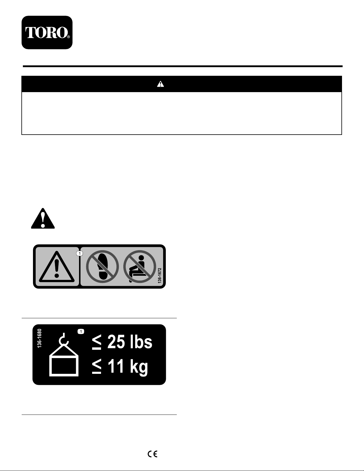
1.Warning—donotstep;noriders.
decal136-1672
136-1672
136-1680
1.Maximumweightis11kg(25lb)
©2017—TheToro®Company
8111LyndaleAvenueSouth
Bloomington,MN55420
Registeratwww.T oro.com.
decal136-1680
OriginalInstructions(EN)
PrintedintheUSA
AllRightsReserved
*3417-288*A
Page 2
Installation
LooseParts
Usethechartbelowtoverifythatallpartshavebeenshipped.
Description
Nopartsrequired
Uppermount1
Mainbracket1
Topbracket1
Lowersupportbracket1
Weldedsupportbracket1
Carriagebolt(5/16x7/8inch)
Nut(5/16inch)
Knob1
Hingebracket1
Nut(1/4inch)
Bolt(1/4x4-1/4inches)
Bolt(5/16x1inch)
Nut(5/16inch)—useonly4for2017andolder
machines
Carriagebolt(5/16x7/8inch)—useonly1for
2017andoldermachines
Innersupportbracket—2018andnewer
machinesonly
Front-weightkit(soldseperately)
Qty.
Use
–
4
3
1
1
3
6
4
1
1
Preparethemachine.
Installthekit.
Mountthekittothemachine.
Installafront-weightkit(ifneeded).
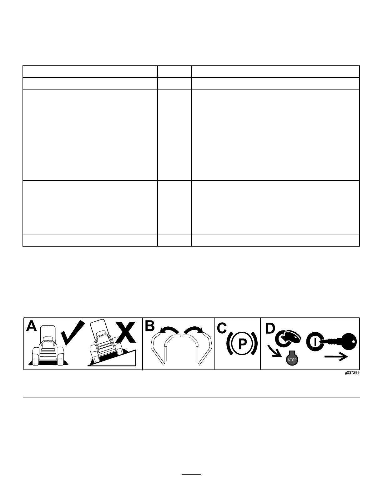
PreparingtheMachine
1.Parkthemachineonalevelsurface.
2.Movethemotion-controlleverstotheNEUTRAL-LOCKposition.
3.Engagetheparkingbrake.
4.Shutofftheengineandremovethekey .
g037289
Figure1
2
Page 3
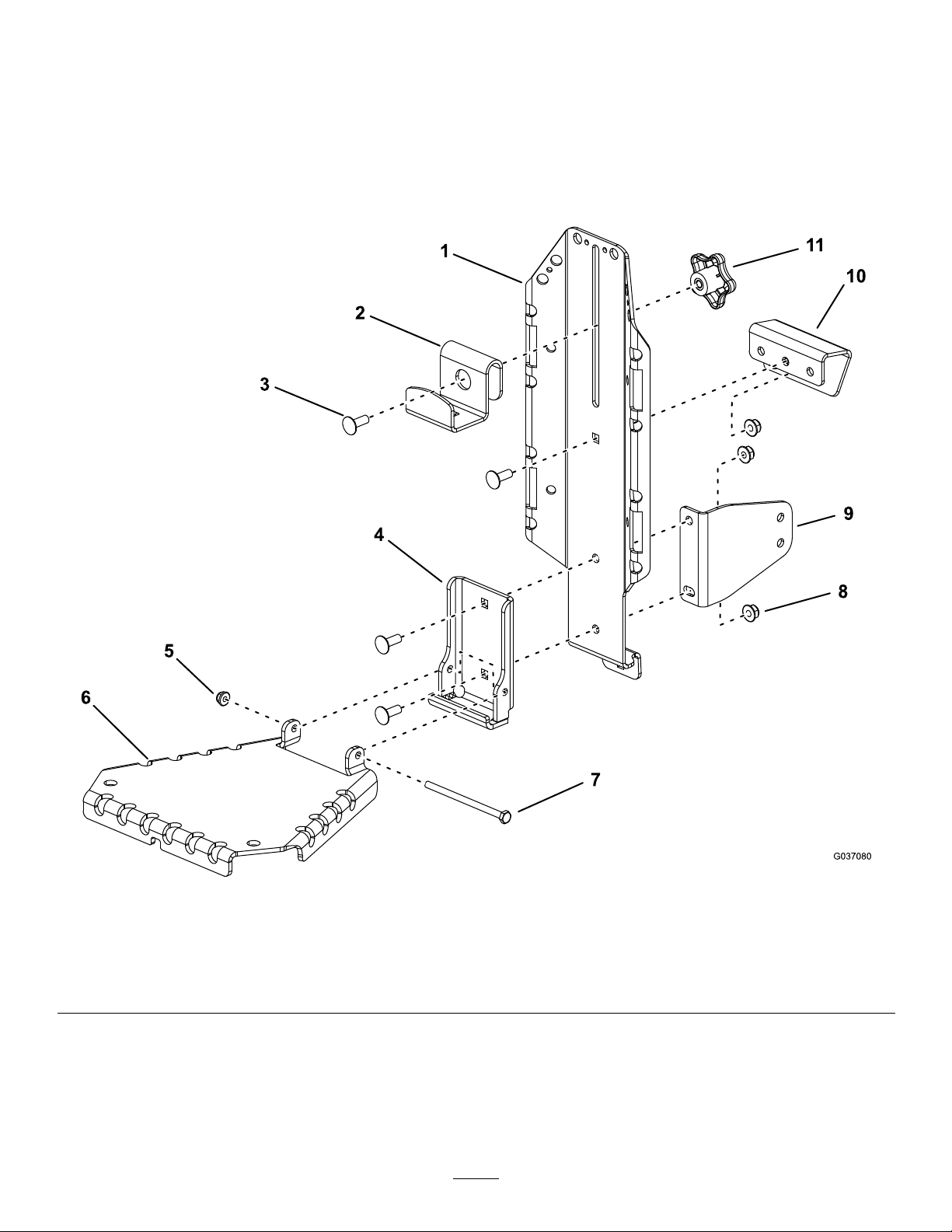
AssemblingtheKit
AssemblethekitasshowninFigure2.Ensuretolooselyinstalltheuppermounttothemainbracket;referto
Figure3todeterminewhichholetouseintheuppermount.
Note:Donotovertightenthebolt(1/4x4-1/4inches)andnut(1/4inch);thehingebracketmustpivotfreely.
Note:Installthelowersupportbracketonlyifyouaremountingthekitinfrontofthereartires.Installthe
bracketsothatthelargefaceisorientedrearwardonthemachine;Figure2showsthebracketorientation
formountingthekitontheleftsideofthemachine.
1.Mainbracket4.Weldedsupportbracket
2.Topbracket
3.Carriagebolt(5/16x7/8
inch)
5.Nut(1/4inch)8.Nut(5/16inch)
6.Hingebracket
Figure2
7.Bolt(1/4x4-1/4inches)
9.Lowersupportbracket(if
needed)
3
g037080
10.Uppermount
11.Knob
Page 4
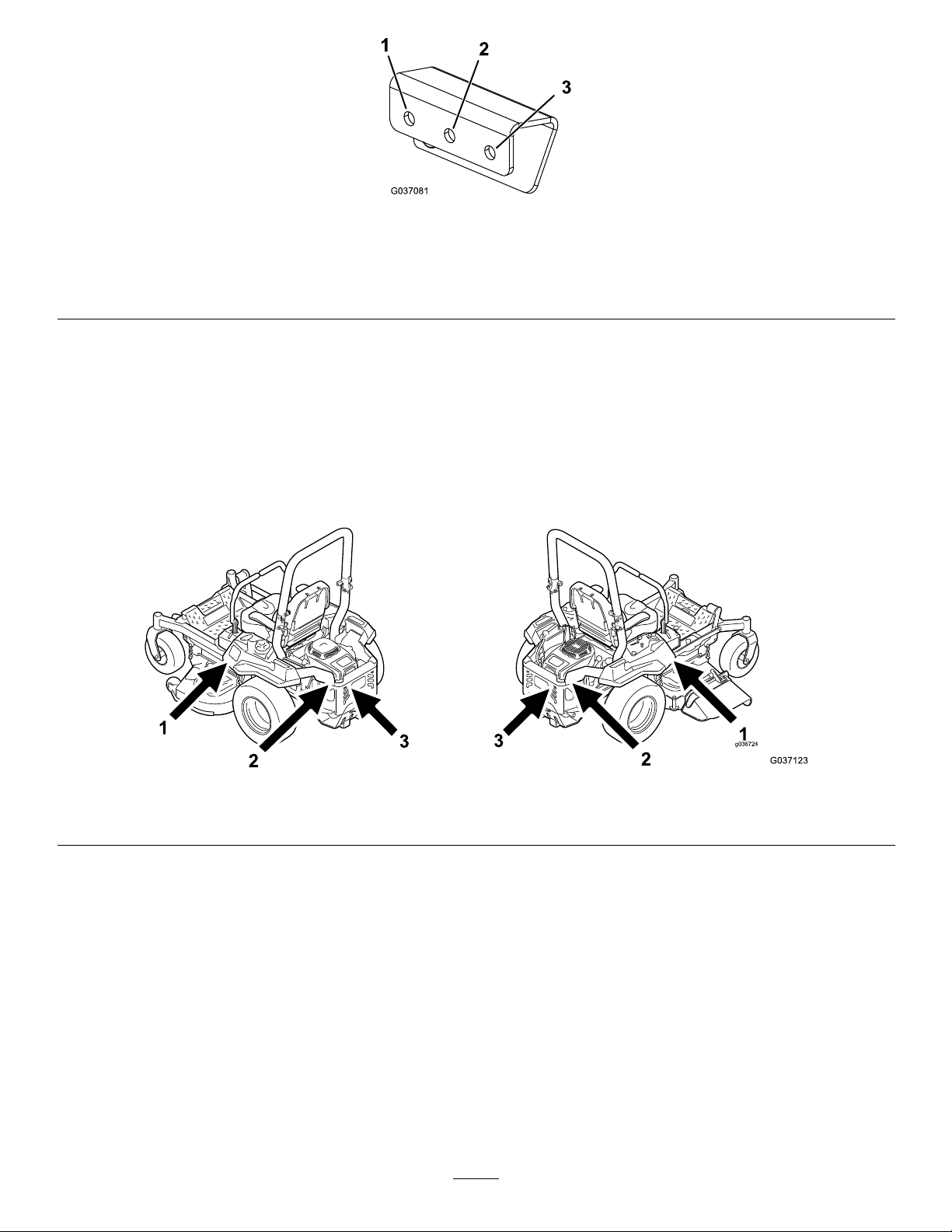
Figure3
g037081
1.Usethisholeifyouaremountingthekitinfrontoftheleft,
reartire.
2.Usethisholeifyouaremountingthekitinanylocationbehind
thereartires.
3.Usethisholeifyouaremountingthekitinfrontoftheright,
reartire.
MountingtheKittotheMachine
MountingLocations
Youcanmountthiskitin6locationsonthemachine(Figure4).Referto1ofthefollowingprocedurestomount
thekitinthedesiredlocation.
Note:For1500Seriesmachines,youcanonlymountthekitinthe2locationsinfrontofthereartires.
1.Infrontofthereartire2.Sideoftheengineguard
g037123
Figure4
3.Rearengineguard
4
Page 5

MountingtheKitinFrontoftheRearTires
For2017andOlderMachines
1.Securethemountassemblytotheconsolecoverusing2bolts(5/16x1inch)and2nuts(5/16inch)as
showninFigure5orFigure6.
2.Tightenthefastenerssecuringtheuppermounttothemainbracket.
3.Securethelowersupportbrackettotherearsideofthebracketundertheconsolecoverusing1bolt(5/16
x1inch)and1nut(5/16inch)asshowninFigure5orFigure6.
Note:Youwillnotusethebottomholeinthemainbracketorlowersupportbracket.
Note:Ensurethattheassemblyisvertical.Ifithangsatanangle,thelowersupportbracketmaybe
installedincorrectly .
Mountingthekittotheleftsideofthemachine
1.Nut(5/16inch)3.Consolecover
2.Mountassembly
4.Bolt(5/16x1inch)
Mountingthekittotherightsideofthemachine
g213937
Figure5
5.Lowersupportbracket
g213938
Figure6
1.Nut(5/16inch)3.Consolecover
2.Mountassembly
4.Bolt(5/16x1inch)
5.Lowersupportbracket
5
Page 6

MountingtheKitinFrontoftheRearTires
For2018andNewerMachines
1.Securethemountassemblytotheconsolecoverusing2bolts(5/16x1inch)and2nuts(5/16inch)as
showninFigure5orFigure6.
2.Tightenthefastenerssecuringtheuppermounttothemainbracket.
3.Securetheinnersupportbrackettothepodsupportbracketusing2carriagebolts(5/16x7/8inch)and2
nuts(5/16inch)asshowninFigure7.
Wheninstallingtheinnersupportbracketontheleftsideofthemachine,orienttheinnersupportbracket
asshowninFigure8.
Wheninstallingtheinnersupportbracketontherightsideofthemachine,orienttheinnersupport
bracketasshowninFigure9.
Figure7
Mountingthekittotheleftsideofthemachine
1.Carriagebolt(5/16x7/8inch)3.Nut(5/16inch)
2.Podsupportbracket4.Innersupportbracket
Figure8
Mountingthekittotheleftsideofthemachine
g225566
g225567
6
Page 7

g225568
Figure9
Mountingthekittotherightsideofthemachine
4.Securethelowersupportbrackettotheinnersupportbracketundertheconsolecoverusing1bolt(5/16x
7/8inch)and1nut(5/16inch)asshowninFigure10.
Note:Youwillnotusethebottomholeinthemainbracketorlowersupportbracket.
Note:Ensurethattheassemblyisvertical.Ifithangsatanangle,thelowersupportbracketmaybe
installedincorrectly .
1.Carriagebolt(5/16x7/8inch)
2.Lowersupportbracket
g225565
Figure10
Mountingthekittotheleftsideofthemachine
3.Innersupportbracket
4.Nut(5/16inch)
7
Page 8

MountingtheKittotheSideoftheEngineGuard
1.Securethemountassemblytothesideupperguardusing2bolts(5/16x1inch)and2nuts(5/16inch)as
showninFigure11orFigure12.
2.Tightenthefastenerssecuringtheuppermounttothemainbracket.
3.Securethebottomofthemainbrackettotheengineguardusing1carriagebolt(5/16x7/8inch)and1nut
(5/16inch)asshowninFigure11orFigure12.
Figure11
Mountingthekittotheleftsideoftheengineguard
g213949
1.Nut(5/16inch)4.Sideupperguard
2.Bolt(5/16x1inch)
3.Carriagebolt(5/16x7/8inch)andnut(5/16inch)
5.Mountassembly
Figure12
Mountingthekittotherightsideoftheengineguard
1.Nut(5/16inch)4.Sideupperguard
2.Bolt(5/16x1inch)
3.Carriagebolt(5/16x7/8inch)andnut(5/16inch)
5.Mountassembly
g213950
8
Page 9

MountingtheKittotheRearEngineGuard
1.Securethemountassemblytotherearupperguardusing2bolts(5/16x1inch)and2nuts(5/16inch)
asshowninFigure13orFigure14.
2.Tightenthefastenerssecuringtheuppermounttothemainbracket.
3.Securethebottomofthemainbrackettotherearengineguardusing1carriagebolt(5/16x7/8inch)and
1nut(5/16inch)asshowninFigure13orFigure14.
Figure13
Mountingthekittotheleftsideoftherearengineguard(rollbarnotshownforclarity)
g213966
1.Carriagebolt(5/16x7/8inch)
2.Rearupperguard
Mountingthekittotherightsideoftherearengineguard(rollbarnotshownforclarity)
1.Carriagebolt(5/16x7/8inch)
2.Rearupperguard
3.Rearengineguard
4.Bolt(5/16x1inch)
3.Rearengineguard
4.Bolt(5/16x1inch)
5.Nut(5/16inch)
6.Mountassembly
g213967
Figure14
5.Nut(5/16inch)
6.Mountassembly
9
Page 10

InstallingaFront-Weight
MountingaBucket
Kit
ForMachineswith2orMore
Accessory-MountKits
If2ormoreaccessory-mountkits(i.e.,bucketkitor
universalmountkit)areaddedtoanyofthe4locations
showninFigure15,addafront-weightkit.Contact
yourAuthorizedServiceDealerforthefront-weightkit.
Note:Ifdesired,youcanremovethehingebracket
andmountthebucketusingtheweldedsupport
bracket.
1.Loosentheknobandraisethetopbracket.
Tightentheknobtoholditinplace(Figure16).
2.Ifyouremovedthehingebracket,placethe
bottomlipofthebucketoverthebottomledgeof
theweldedsupportbracket(Figure16).
3.Loosentheknobandlowerthetopbracketasfar
aspossibleovertherimofthebucket.Tighten
theknob(Figure16).
Figure15
1.Addafront-weightkitwhen2ormoreaccessory-mountkits
areinstalledatthesepositions.
Operation
MountingAttachments
UseonlyToro-approvedattachmentsandaccessories.
Themaximumcapacityis11.3kg(25lb).
Usethetopbracketandhingebracketformounting
attachmentsoraccessories;securethemusingthe
holesinthemountingbrackets.
Securethehingebracketwhennotinuse;referto
SecuringtheHingeBracket(page11).
g037417
g037421
Figure16
1.Knob
2.Topbracketovertherimof
thebucket
10
3.Bottomledgeofthe
supportbracket
Page 11

SecuringtheHingeBracket
1.Raisethehingebracket.
2.Loosentheknobandlowerthetopbracket,
insertingthetabintothenotchinthehinge
bracket(Figure17).
3.Tightentheknob.
Figure17
1.Tabintopbracket2.Notchinhingebracket
g037423
11
Page 12

 Loading...