

Page 1
MudPumpSpeedControlKit
DD4045DirectionalDrill
ModelNo.136-1599
ThisproductcontainsachemicalorchemicalsknowntotheStateofCalifornia
tocausecancer,birthdefects,orreproductiveharm.
PreparingtheMachine
1.Movethemachinetoalevelsurface.
2.Shutofftheengineandremovethekey .
FormNo.3415-323RevA
InstallationInstructions
WARNING
CALIFORNIA
Proposition65Warning
3.Setthebattery-disconnectswitchtotheOFFposition.
InstallingtheKit
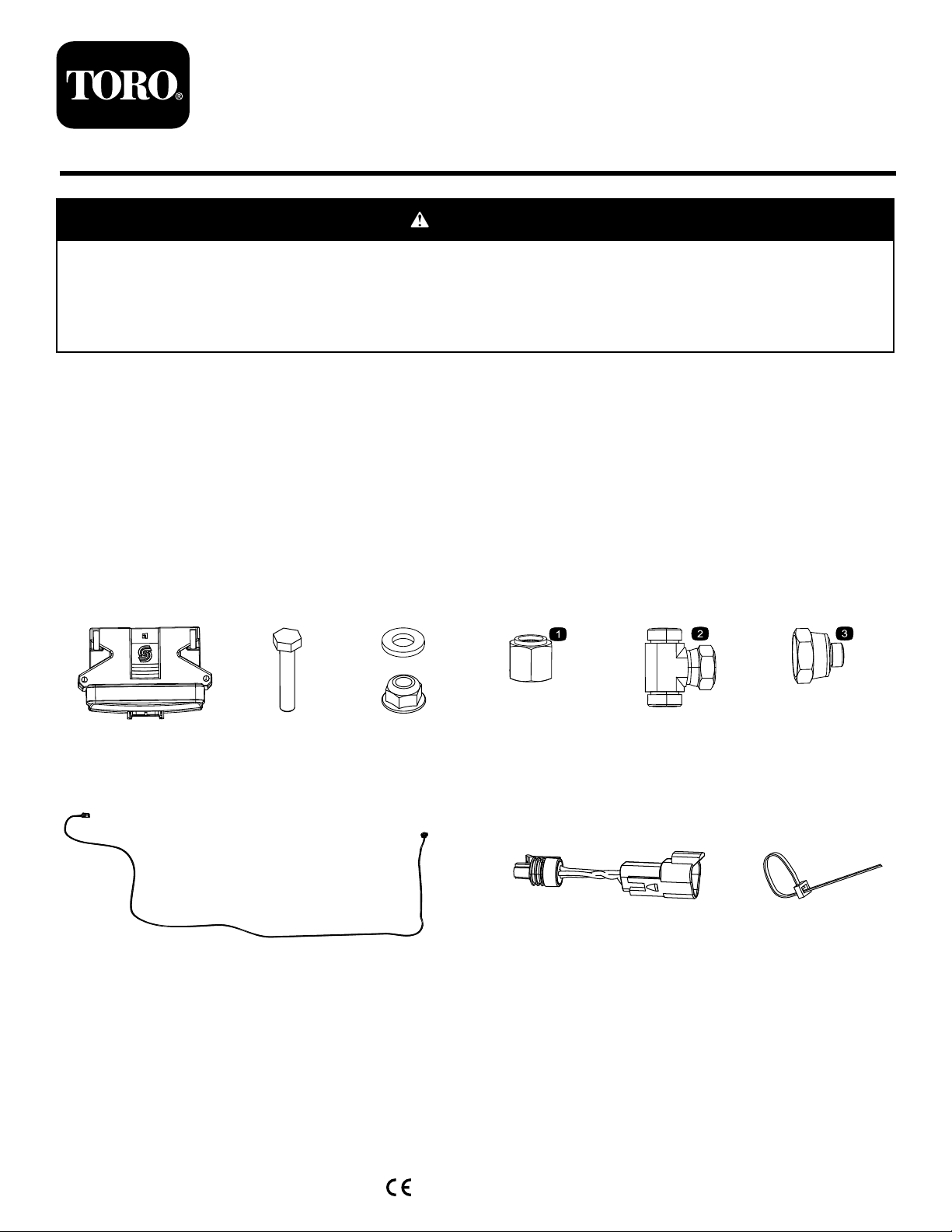
LooseParts
1x2x
2x(washer)
1x1x1x
2x(nut)
©2017—TheToro®Company
8111LyndaleAvenueSouth
Bloomington,MN55420
1x1x10x
Registeratwww.T oro.com.
OriginalInstructions(EN)
PrintedintheUSA
AllRightsReserved
*3415-323*A
Page 2
InstallingtheMicroprocessor
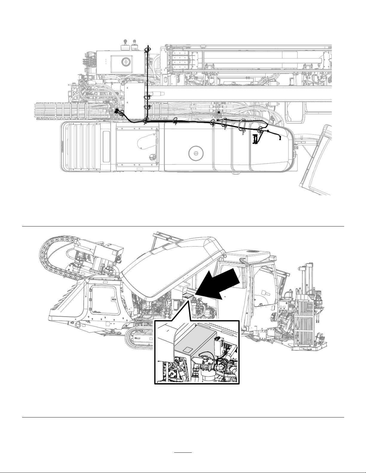
Important:Donotroutethewireharnessnearmovingpartswhereitwillbepinchedorcut.
Figure1
OverviewoftheWireHarness
g212368
Figure2
LocationofMicroprocessorInstallation
g212363
2
Page 3
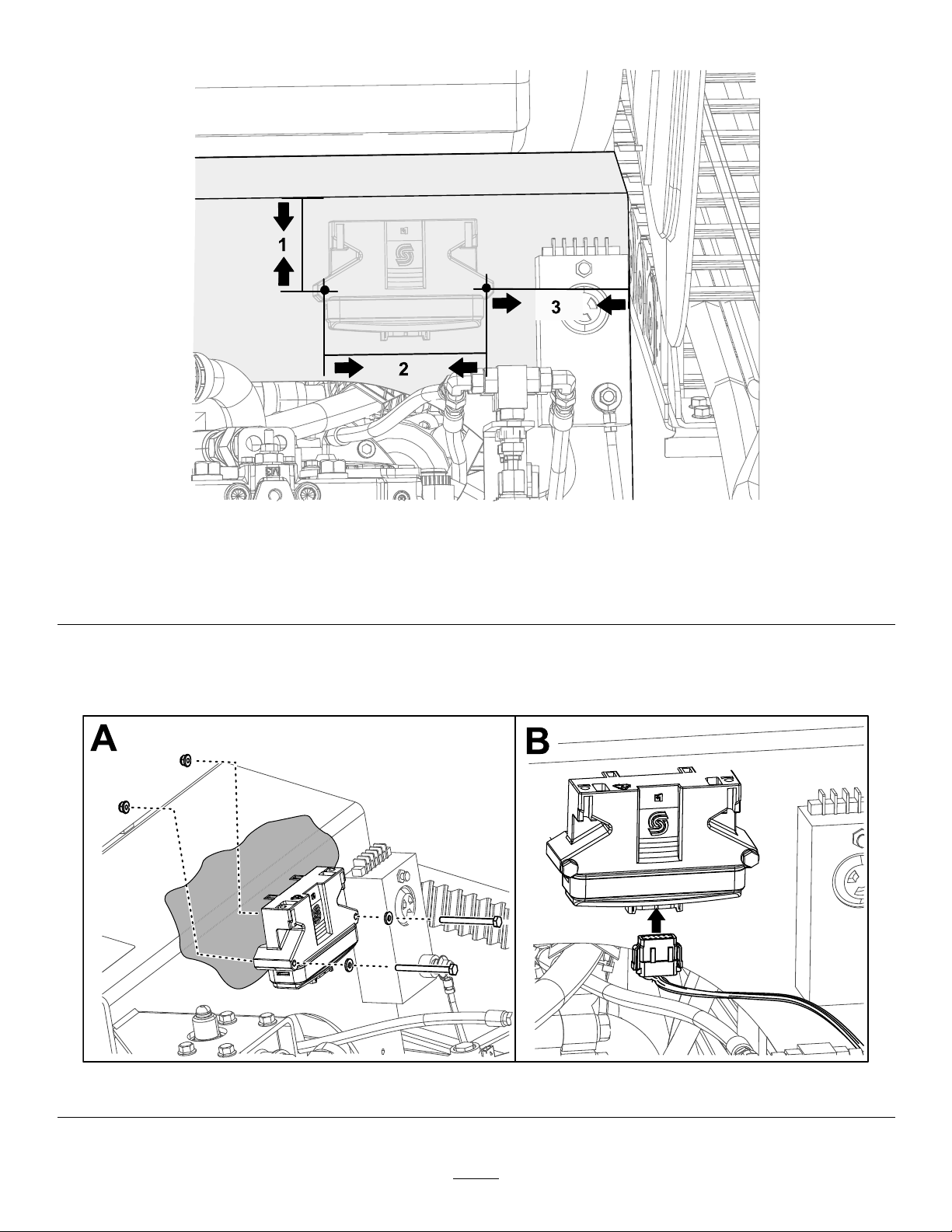
1.Drill2holesintothepanel(Figure2)usingthemeasurementsfromFigure3.
Figure3
1.3-1/2inchesfromthetopedgetothecenterofthehole.3.5-1/8inchesfromtheedgeofthepaneltothecenterofthe
hole.
2.5-11/16inchesfromthecenterof1holetothecenterofthe
otherhole.
2.Securethemicroprocessortothepanel(Figure2)using2bolts(1/4x23/4inches),2washers,and
2nuts(1/4inch)asshowninBoxAofFigure4.
3.PlugthewireharnessintothemicroprocessorasshowninBoxBofFigure4.
g212414
Figure4
3
g212415
Page 4

ConnectingtheWireHarnesstotheHydrostatPump
1.Routethewireharnessdowntothehydrostatpump.
2.Removethecurrentwireharnessfromthehydrostatpump(BoxAofFigure5).
3.Plugthecurrentwireharnessintothenewwireharness(BoxBofFigure5).
4.Installthenewwireharnessconnectorinthehydrostatpump(BoxCofFigure5).
Figure5
4
g212418
Page 5

DisconnectingtheTransducer
Routethewireharnessalongtheframewiththecurrentwireharnesses(Figure6andFigure7).
Figure6
g212590
Figure7
5
g212364
Page 6

1.Locatethetransducerbelowthebulkhead,justabovethefuel-tanksendingunit(Figure7).
2.Disconnectthewireharnessfromthetransducertting(BoxAofFigure8).
3.Removethetransducerassemblyandttingcurrentlyinstalled(BoxAofFigure8).
4.Installthecapontotheport(BoxBofFigure8).
5.Movethecurrentharnessesovertotheframeandconnectittothenewwireharness(BoxCofFigure8).
6.Securethewireharnessusingcableties.
Figure8
g212365
InstallingtheTransducer
g212366
Figure9
Installtransducer
6
Page 7

1.Removethehosefromthettingontherearcontrolweldment(BoxAofFigure10).
Figure10
2.Removethettingfromtherearcontrolweldment(BoxBofFigure10).
3.Installtheteettingontherearcontrolweldment(BoxCofFigure10).
4.Installthehoseontotheteetting(BoxDofFigure10).
5.Installthettingremovedin2,showninBoxBofFigure10(BoxAofFigure11).
g213031
Figure11
6.InstallthereducerandO-rings(BoxBofFigure1 1).
7.Installthetransducerassemblyremovedin3ofDisconnectingtheTransducer(page5)(BoxCof
Figure1 1).
8.Routetheharnessalongthecurrentharnessesovertothetransducer(Figure12).
Figure12
g213032
g212417
7
Page 8

9.Iftheharnessdoesnottintothetransducer,connecttheharnessandtransducerusingtheadapter
(Figure13).
Figure13
ConnecttheWireHarnesstotheMudPumpSensor
Routetheharnesstothemudpumpsensor(BoxesAandBofFigure14)attherearofthemachine.
g213030
Figure14
1.Disconnectthecurrentharness(BoxAofFigure15).
2.Connectthecurrentharnesstothenewharness(BoxBofFigure15).
3.Connectthenewharnesstothemudpumpsensor(BoxCofFigure15).
Figure15
1.Currentharness
2.Newharness
g213044
g213043
8
 Loading...