

Page 1

Installation
LooseParts
FormNo.3407-721RevA
BrakeReplacementKit
Twister
ModelNo.136-1199
®
orWorkman
Proposition65Warning
ThisproductcontainsachemicalorchemicalsknowntotheStateofCaliforniato
causecancer,birthdefects,orreproductiveharm.
®
UtilityVehicle
InstallationInstructions
WARNING
CALIFORNIA
Usethechartbelowtoverifythatallpartshavebeenshipped.
ProcedureDescription
1
2
3
4
5
Nopartsrequired
Nopartsrequired
Rightspindle1
Leftspindle
Brake-caliperassembly2
Flange-headbolt(3/8x1inch)
Rotor2
Hex-socketbolt(5/16x3/4inch)
Frontbrake-lineassembly1
Banjowasher4
Banjobolt2
Clip
Bleedscrew2
Nopartsrequired
Nopartsrequired
Qty.
Use
–
–
1
4
8
2
–
–
Preparethemachine.
Removetheexistingbrakeassembly.
Installthenewbrakeassembly.
Bleedthebrakecalipers.
Installthewheels.
6
7
©2016—TheT oro®Company
8111LyndaleAvenueSouth
Bloomington,MN55420
Nopartsrequired
Nopartsrequired
Registeratwww.T oro.com.
–
–
Adjustthefrontwheeltoe-in.
Burnish(break-in)thebrakes.
OriginalInstructions(EN)
PrintedintheUSA
AllRightsReserved
*3407-721*A
Page 2
1
PreparingtheMachine
NoPartsRequired
Procedure
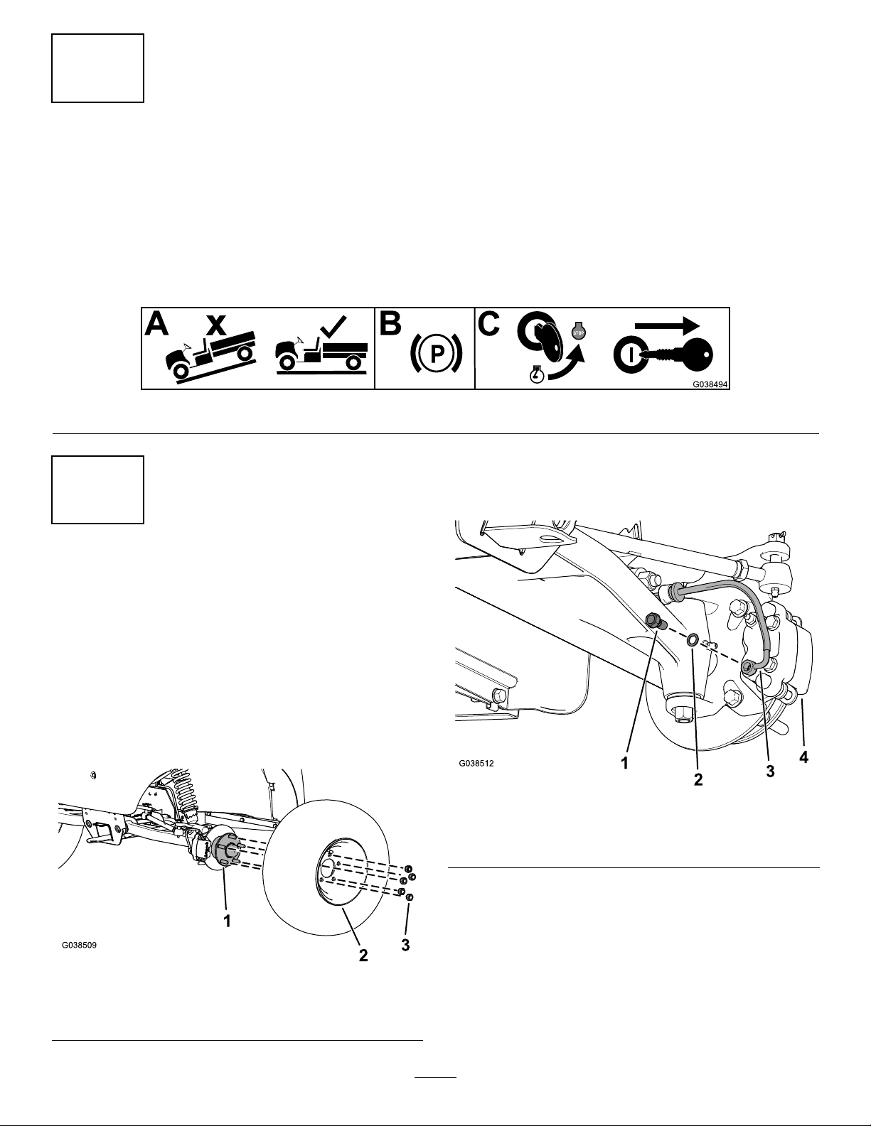
1.Parkthemachineonalevelsurface.
2.Engagetheparkingbrake.
3.Shutofftheengineandremovethekeyfromthekeyswitch.
2
Figure1
3.Removethebanjoboltandwasherfromthe
brake-caliperassembly ,andremovethefrontbrakeline
fromthebrake-caliperassembly(Figure3).
RemovingtheExistingBrake
Assembly
NoPartsRequired
Procedure
1.Liftthefrontofthemachineandsupportitwithjack
stands.
2.Removethelugnutsthatsecurethewheeltothehub
(Figure2).
Figure3
1.Banjobolt3.Frontbrakeline
2.Banjowasher4.Brake-caliperassembly
Figure2
1.Hub3.Lugnut
2.Wheel
2
Page 3
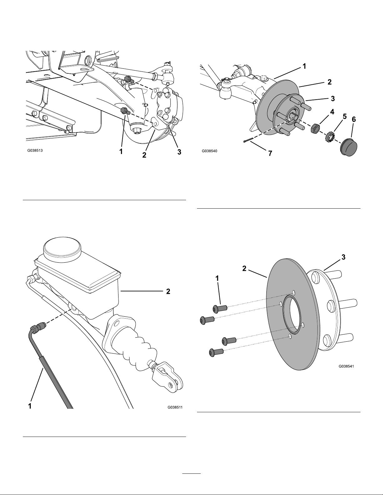
4.Removetheange-headbolts(3/8x1inch)that
securethebracketforthebrake-caliperassemblytothe
spindleandremovethebrake-caliperassemblyfrom
thespindle(Figure4).
6.Removethedustcap,hairpincotter,nutretainer,and
jamnut,andremovethehubandrotorfromthe
spindle(Figure6).
Note:Retainthehub,dustcap,jamnut,nutretainer,
andhairpincotter.
Figure4
1.Flange-headbolt(3/8x1
inch)
2.Spindle
3.Caliperbracket
(brake-caliperassembly)
5.Removethefrontbrakelinefromthemastercylinder
(Figure5).
Note:Discardthefrontbrakeline.
Figure6
1.Spindle
2.Rotor6.Dustcap
3.Hub7.Hairpincotter
4.Jamnut
5.Nutretainer
7.Removethe4hex-socketbolts(5/16x3/4inch),and
removetherotorfromthehub(Figure7).
Note:Discardtherotorand4hex-socketbolts(5/16
x3/4inch).
Figure5
1.Frontbrakeline2.Mastercylinder
1.Hex-socketbolt(5/16x3/4
inch)
2.Rotor
3
Figure7
3.Hub
Page 4

8.Removethehairpincotterandslottedhexnutfrom
thetierodballjoint,anddisconnectthetierodfrom
thespindle(Figure8).
Note:Retainthehairpincotterandslottedhexnut.
Figure8
1.Tierod
2.Hairpincotter
3.Balljoint
9.Removethehex-headbolt(1/2x6inches),clip,and
locknut(1/2inch)fromthecontrolarm,andremove
thespindle(Figure9).
4.Spindle
5.Slottedhexnut
3
InstallingtheNewBrake
Assembly
Partsneededforthisprocedure:
1Rightspindle
1
Leftspindle
2Brake-caliperassembly
4
Flange-headbolt(3/8x1inch)
2Rotor
8
Hex-socketbolt(5/16x3/4inch)
1Frontbrake-lineassembly
4Banjowasher
2Banjobolt
2
Clip
2Bleedscrew
Note:Retainthehex-headbolt(1/2x6inches)and
locknut(1/2inch).
Note:Discardthespindle.
Figure9
1.Hex-headbolt(1/2x6
inches)
2.Clip4.Locknut(1/2inch)
3.Spindle
Procedure
1.Installthefrontbrakelinetothemastercylinder
(Figure5).
2.Installthespindleassemblytothecontrolarmusing
thehex-headbolt(1/2x6inches),clip,andlocknut
(1/2inch)asshowninFigure9.
3.Torquethelocknut(1/2inch)to102to136N∙m(75
to100ft-lb).
4.Installthetierodtothespindleassemblyusingthe
slottedhexnutandhairpincotter(Figure8).
Note:Iftheholedoesnotaligntoinstallthecotter
key,tightenonlytoaligntheslottednuttoensurethat
theholeforthehairpincotterisvisible,theninstall
thehairpincotter.
5.Torquetheslottedhexnutto27to34N∙m(20to25
ft-lb).
6.Installtherotortothehubusing4hex-socketbolts
(5/16x3/4inch)asshowninFigure7.
7.Torquethe4hex-socketbolts(5/16x3/4inch)to12
to15N∙m(9to11ft-lb).
10.Repeatsteps2through9ontheothersideofthe
machine.
4
Page 5

8.Installtherotorandhubassemblytothespindleby
performingthefollowing:
A.Tightenthejamnutwhileturningthehubtoseat
thebearings,andtorquethejamnutto16to20
N∙m(12to15ft-lb)asshowninFigure6.
B.Loosenthejamnutuntilitisawayfromthetab
washerandhub,andtorquethejamnutto169to
226N∙cm(15to20in-lb)whilerotatingthehub
(Figure6).
C.Installthenutretaineroverthejamnut,ensure
thattheholeforthehairpincotterisvisible,and
installthehairpincotter(Figure6).
D.Installthedustcap(Figure6).
9.Installthenewbrake-caliperassemblytothespindle
using2ange-headbolts(3/8x1inch)asshownin
Figure4.
10.Torquethe2ange-headbolts(3/8x1inch)to47to
54N∙m(35to40ft-lb).
11.Installthebleedscrewintothetopholeofthe
brake-caliperassembly(Figure10).
4
BleedingtheBrakeCalipers
NoPartsRequired
Procedure
Important:Y ouwillneed2peopletoperformthis
procedure.
1.Pushdownthebrakepedalfully.
2.Withbrakepedalpusheddownfully,loosenthebleed
screw1/4turn(Figure11).
3.Withbrakepedalpusheddownfully,tightenthebleed
screw1/4turn(Figure11).
Figure10
1.Bleedscrew
12.Torquethebleedscrewto6to7.5N∙m(4.5to5.5ft-lb).
13.Installthefrontbrakelinetothebrake-caliperassembly
usingabanjoboltand2banjowashers(Figure3).
14.Torquethebanjoboltto12to15N∙m(9to11ft-lb).
2.Topholeofthe
brake-caliperassembly
Figure11
4.Repeatthisprocessuntilairnolongerreleasesfrom
thecalipers.
Note:Whenairnolongerreleases,youshouldnotsee
anymoreairbubblesinthebrakeuid.
5.Fillthemastercylinderwithbrakeuid;refertoyour
Operator’sManual.
5
Page 6

5
G009235
1
2
3
InstallingtheWheels
NoPartsRequired
Procedure
1.Installthewheelontothehubusingthepreviously
removedlugnuts(Figure2).
1.Measurethedistancebetweenbothofthefronttiresat
theaxleheightatboththefrontandrearofthefront
tires(Figure12).
2.Torquethelugnutsinastarpatternto102to129N∙m
(75to95ft-lb).
6
AdjustingtheFrontWheel
Toe-in
NoPartsRequired
Procedure
Thetoe-inshouldbe0to6mm(0to1/4inch).
•Checkthetirepressuretoensurethatthefronttiresare
inatedto82kPa(12psi).
•Either,addweighttothedriver'sseatequaltotheaverage
operatorwhowillrunthemachine,orhaveanoperator
sitontheseat.Theweightoroperatormustremainon
theseatforthedurationoftheprocedure.
Figure12
1.Tirecenterline—back3.Axlecenterline
2.Tirecenterline—front
2.Ifthemeasurementdoesnotfallwithin0to6mm(0
to1/4inch),loosenthejamnutsattheouterendof
thetierods(Figure13).
Figure13
1.Tierod2.Jamnut
•Onalevelsurface,rollthemachinestraightback2to3
m(6to10ft)andthenstraightforwardtotheoriginal
startingposition.Thisallowsthesuspensiontosettleinto
theoperatingposition.
•Measurethetoe-inwiththewheelsfacingstraightahead.
3.Rotatebothtierodstomovethefrontofthetire
inwardoroutward.
4.Tightenthetierodjamnutswhentheadjustmentis
correct.
5.Ensurethatthereisfulltravelofthesteeringwheelin
bothdirections.
6
Page 7

7
BurnishingtheBrakes
NoPartsRequired
Procedure
Toensureoptimumperformanceofthebrakesystem,burnish
(break-in)thebrakesbeforeuse.
1.Bringthemachineuptofullspeed,applythebrakesto
rapidlystopthemachinewithoutlockingupthetires.
2.Repeatthisprocedure10times,waiting1minute
betweenstops,toavoidoverheatingthebrakes.
Important:Thisprocedureismosteffectiveifthe
machineisloadedwith227kg(500lb).
7
Page 8

 Loading...