

Page 1
FieldKit
2024DirectionalDrill
ModelNo.133-9467
ThisproductcontainsachemicalorchemicalsknowntotheStateofCaliforniato
causecancer,birthdefects,orreproductiveharm.
Safety
SafetyandInstructionalDecals
FormNo.3408-241RevA
InstallationInstructions
WARNING
CALIFORNIA
Proposition65Warning
Safetydecalsandinstructionsareeasilyvisibletotheoperatorandarelocatednearanyareaofpotential
danger.Replaceanydecalthatisdamagedormissing.
117–2718
©2016—TheToro®Company
8111LyndaleAvenueSouth
Bloomington,MN55420
Registeratwww.T oro.com.
OriginalInstructions(EN)
PrintedintheUSA
AllRightsReserved
*3408-241*A
Page 2
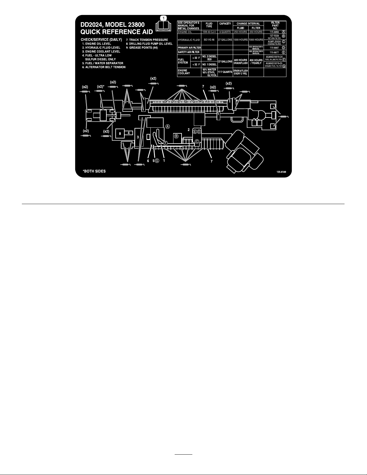
1.ReadtheOperator'sManualformoreinformationonservicingthemachine.
125-6189
2
Page 3
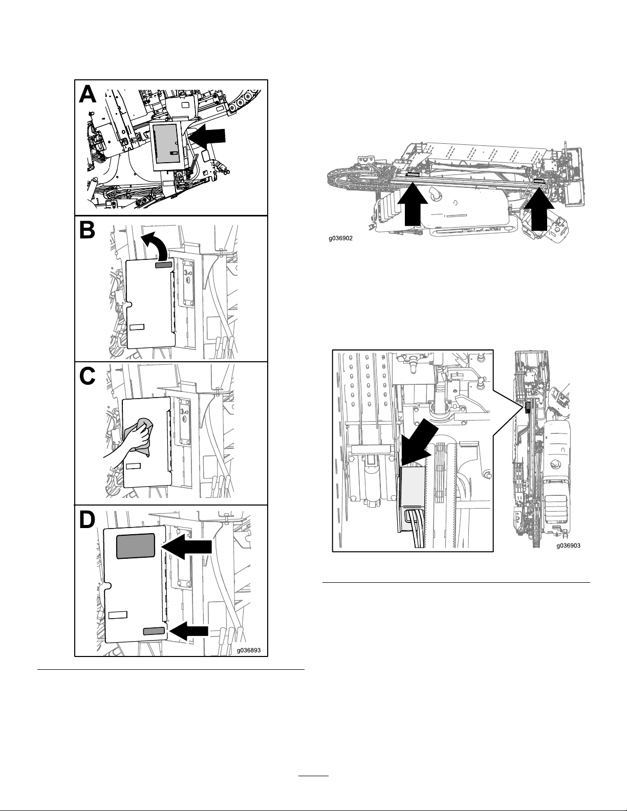
InstallingtheDecals
WeldingtheRod-Box
Removethecurrentdecal,cleanthesurface,andinstallthe
newdecals.
Thrust-FrameSupports
1.Parkthemachineonahardlevelsurface.Shutoffthe
engine,removethekey,andsetthebatterydisconnect
switchtoOFF.
2.Locatethethrust-framesupportsnearthecam
assemblies.
3.Removeallofthepaintanddirtonthefrontandrear
thrust-framesupports.
Note:Protectthehosesandwiringharnessnearthe
thrust-framesupports.
4.Weldahorizontalweldalongthefrontandrear
thrust-framesupports.
Frontthrust-framesupport(horizontalweld)
3
Page 4

Rearthrust-framesupport(horizontalweld)
Rearthrust-framesupport(verticalweld)
5.Inspecttheverticalweldonthefrontandrear
thrust-framesupports.Iftheweldshowssignsof
fatigue,repeatstep3andweldthisarea.
Frontthrust-framesupport(verticalweld)
6.Aftertheweldscool,primeandpainttheweldedareas
withsemi-glossblackpaint.
4
Page 5

InstallingtheExhaust
InstallingandModifyingthe
InsulationRetainerRing
Removetheinsulation,foldtheretainerringontheinsulation
piece,andinstalltheassembly.
FrontHoodLatches
1.Removethecurrenthoodlatchandinstallthenew
hoodlatch.
2.Openthefronthoodanddisconnecttheinternalfront
hoodlatch.
3.Grinddownthetipoftheinternalfronthoodlatch.
Note:Ensurethatyouleavethehooklength1.6cm
(0.63inch)long.
5
Page 6

4.Installtheinternalfronthoodlatch.
4.Shutofftheengine,removethekey,andsetthe
battery-disconnectswitchtoOFF.
5.Supportthethrustframewithaliftingstrapconnected
toanoverheadcrane.
6.Loosenthelefttracktension;refertotheOperator’s
Manualforthemachine.
InstallingtheThrustFrame
PivotPin
1.Parkthemachineonahardlevelsurface.
2.Removethedrillpipesfromthepipebox.
3.Lowerthestake-downplatetotheground,raisethe
footstabilizers,andpositionthecarriageintheforward
position.
7.Locatethethrustframepivotpin.
8.Insertblocksbetweentheupperpartofthetrackand
thetrackframe.
9.Removethepivotpinkeeperboltandpin.
10.Begintoslideoutthecurrentpivotpin.
Note:Tackweldalargeslidehammertotheretainer
endofthepinandusetheslidehammertopullthepin
orusealongbarorpipeasadriveanddrivethepin
outfrombetweentherighttrackandthemainframe
ofthedrill.
11.Installthetemporarypinontheothersideofthethrust
frameandcontinuetoslideoutthecurrentpivotpin.
6
Page 7

12.Replacethebushing.
Note:Ifthebushingisweldedinplace,grindtheweld
smoothbeforeinstallingthenewpin.
14.Removethetemporarypinandreplacethebushing.
Note:Ifthebushingisweldedinplace,grindtheweld
smoothbeforeinstallingthenewpin.
15.Pushthenewpinallthewayin.
13.Addgreasetothenewpivotpinandpushitinalmost
allthewayin.
16.Usingthepivotagpinasaguide,drillaholeintothe
thrustframe.
17.Installthebolt,washer,andnut.
18.Installtheretainerringontheotherendofthenew
pivotpin.
7
Page 8

19.Cleanthegreasettingsandpumpgreaseintothe
ttingsuntilgreasebeignstooozeoutofthebearings.
20.Wipeupanyexcessgrease.
21.Removetheblocksfromthetrack.
22.Tightenthelefttracktension;refertotheOperator’s
Manualforthemachine.
23.Removethestrapfromthethrustframeandlowerthe
thrustframebackintothestowedposition.
24.SetthebatterydisconnectswitchtoON.
8
 Loading...