

Page 1

LiftHoseKit
TX1000CompactToolCarrier
ModelNo.133-8590
WARNING
CALIFORNIA
Proposition65Warning
ThisproductcontainsachemicalorchemicalsknowntotheStateofCaliforniato
causecancer,birthdefects,orreproductiveharm.
Note:Determinetheleftandrightsidesofthemachinefromthenormaloperatingposition.
Installation
FormNo.3413-815RevA
InstallationInstructions
LooseParts
Usethechartbelowtoverifythatallpartshavebeenshipped.
ProcedureDescription
1
2
3
4
5
6
Nopartsrequired
Nopartsrequired
Longtrimseal2
Shorttrimseal
Righthoses2
Hosesleeve1
Cabletie
Lefthose
Hosenut2
Hosesleeve1
Cabletie
Nopartsrequired
Qty.
Use
–
–
2
2
2
2
–
Preparethemachine.
Removethehoses.
Installthetrimseals.
Replacingtherighthoses.
Installthelefthoses.
Completetheinstallation.
©2017—TheToro®Company
8111LyndaleAvenueSouth
Bloomington,MN55420
Registeratwww.T oro.com.
OriginalInstructions(EN)
PrintedintheUSA
AllRightsReserved
*3413-815*A
Page 2
1
PreparingtheMachine
NoPartsRequired
Procedure
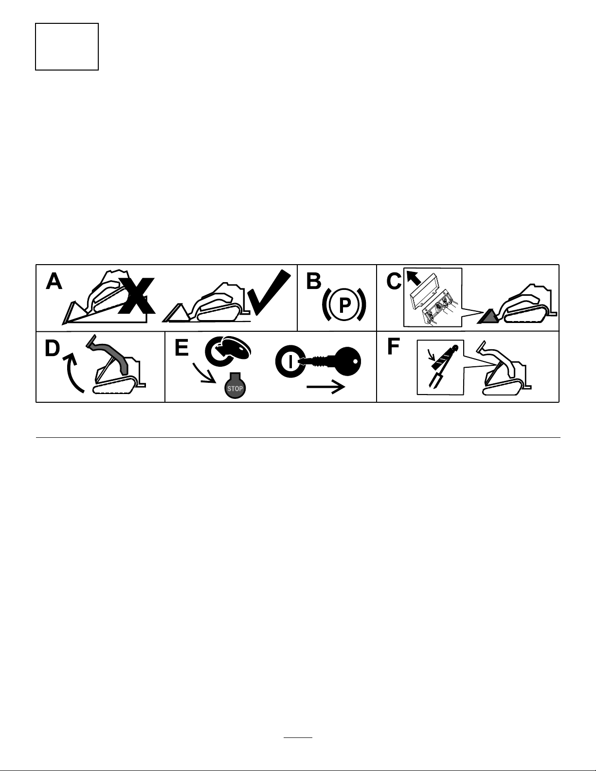
1.Parkthemachineonalevelsurface.
2.Engagetheparkingbrake.
3.Removeanyattachments.
4.Raisetheloaderarms.
5.Shutofftheengineandremovethekey .
6.Installthecylinderlocks.
Figure1
g203664
2
Page 3
2
RemovingtheHoses
NoPartsRequired
Procedure
1.Cycletheloader-valvehandleforwardandbackto
relievepressureinthehydraulic-cylinderhoses.
WARNING
Hydraulicuidescapingunderpressurecan
penetrateskinandcauseinjury.
•Ifhydraulicuidisinjectedintotheskin,
itmustbesurgicallyremovedwithinafew
hoursbyadoctorfamiliarwiththistype
ofinjury.Gangrenemayresultifthisis
notdone.
•Keepyourbodyandhandsawayfrom
pinholeleaksornozzlesthateject
high-pressurehydraulicuid.
•Usecardboardorpapertondhydraulic
leaks.
•Safelyrelieveallpressureinthehydraulic
systembeforeperforminganyworkonthe
hydraulicsystem.
•Makesurethatallhydraulic-uidhoses
andlinesareingoodconditionandall
hydraulicconnectionsandttingsare
tightbeforeapplyingpressuretohydraulic
system.
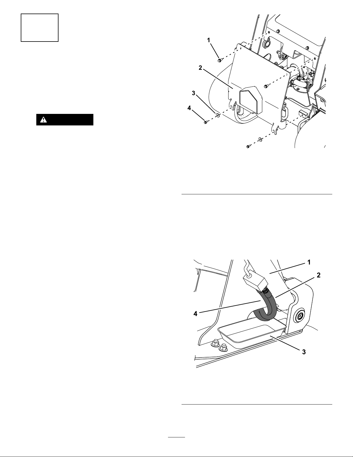
2.Usinga9/16-inchsocket,removethe2upperbolts
(3/8x1inch)fromthefrontcover(Figure2).
Figure2
1.Upperbolt(2)—3/8x1
inch
2.Frontcover
3.Usinga1/2-inchsocket,removethe2lowerbolts
(5/16x5/8inch),2washers,andfrontcover(Figure2).
4.Placeanoilcontainerorabsorbenttowelsunder
thehydrauliccylinderhosesontherightsideofthe
machine(Figure3).
5.Removetheouterandinnerhosesusinga13/16-inch
open-endwrench(Figure3).
3.Washer(2)
4.Lowerbolt(2)—5/16x5/8
inch
g204032
Figure3
1.Hydrauliccylinder
2.Outerhydraulichose
6.Drainanyexcessuidfromthehoses.
3
3.Container
4.Innerhydraulichose
g203988
Page 4

7.Usinga13/16-inchwrench,removetherightouterand
innerhydraulichosesfromtheteettings(Figure4).
Figure4
g204068
Figure5
1.Longtrimseal
3.Presstheshorttrimsealovertheouterframe(Figure
6).
g203989
1.Right,innerhydraulichose
2.Innerteetting5.Left,outerhydraulichose
3.Outerteetting
8.Removethehosesthroughtheframeopeningand
discardthem.
9.Repeatsteps4through8fortheothersideofthe
machine.
4.Left,innerhydraulichose
6.Right,outerhydraulichose
3
InstallingtheTrimSeals
Partsneededforthisprocedure:
2Longtrimseal
2
Shorttrimseal
Procedure
Note:Youmayuseanadhesivetoadherethetrimsealsto
themachineframe.
Figure6
1.Shorttrimseal
4.Repeattheprocedurefortheothersideofthemachine.
4
InstallingtheRightHoses
Partsneededforthisprocedure:
2Righthoses
1Hosesleeve
2
Cabletie
g204069
1.Cleantheinnerandouterframeopeningsofanydirt
andoil.
2.Startingatthetopoftheright,innerframeopening,
pressthelongtrimsealaroundtheopening(Figure5).
Cutthetrimsealsothatitdoesnotoverlap.
Procedure
Note:Therighthoseshave90-degreettingson1end.
1.InspecttheO-ringsintheteettings.Replaceanythat
havecuts/abrasionsoraredamaged.
4
Page 5

2.Removeanyprotectivecoveringfromtheendsofthe
hydraulichoses.
3.Installahosesleeveoverthestraightendsofthehoses,
leavingapproximately15.2cm(6inches)oftheend
exposed(Figure7).
Figure7
1.Hosesleeve
4.Insertthe90-degreehosettingsthroughtheouter
andinnerframeopening.Ensurethatthehosesleeve
liesinsidebothframeopeningsandthatthehosesare
atinsidetheopenings.
5.LooselyconnectbothhosestotheteettingsinFigure
4.
6.Positionthehosesconnectedtotheteettingsothat
theyverticalorslightlyturnedforward.Tightenthe
hosenutsusinga13/16-inchwrench.Torqueto36
to44N∙m(27to33ft-lb).
7.Connectthehosefromtheinnerteettingtotheinner
cylindertting;connectthehosefromtheoutertee
ttingtotheoutercylindertting(Figure8).
2.Approximately15.2cm(6
inches)
5
InstallingtheLeftHoses
Partsneededforthisprocedure:
2
Lefthose
2Hosenut
g204094
1Hosesleeve
2
Cabletie
Procedure
Note:Thelefthoseshaveastraightttingonbothends.
1.InspecttheO-ringsintheteettings.Replaceanythat
havecutsorabrasionsoraredamaged.
2.Removeanyprotectivecoveringfromtheendsofthe
hydraulichoses.
3.Installahosesleeveoverthehoses,leaving
approximately15.2cm(6inches)oftheendexposed
(Figure7).
4.Insertthehosesthroughtheouterandinnerframe
opening.Ensurethatthehosesleeveliesinsideboth
frameopeningsandthatthehosesareatinsidethe
openings.
Figure8
1.Hydrauliccylinder3.Hosesleeve
2.Outerhydraulichose
8.Usea13/16-inchoffsetwrenchtotightenthenuts
whileusinga11/16-inchopen-endwrenchtoholdthe
hosepositions.Torqueto36to44N∙m(27to33ft-lb).
4.Innerhydraulichose
5.Connectthehosestotheinnerandoutercylinder
ttings(Figure8).
Note:Usea13/16-inchoffsetwrenchtotightenthe
nutswhileusinga11/16-inchopen-endwrenchto
holdthehosepositions.
6.Installahosenutontobothteettingssothatthereare
enoughthreadstoseatthehoseends(Figure9).
Note:Youmayalsousehosenutsthatwerepreviously
installedonthetting.
7.Connectthehosefromtheinnercylinderttingto
therearteetting;connectthehosefromtheouter
cylinderttingtothefrontteetting(Figure9).
g204093
Note:Usea13/16-inchwrenchtotightenthehose
nutswhileusinga11/16-inchopen-endwrenchto
holdthehosepositions.
9.Usethecabletiestosecurethehosesleevetothe
hydraulichoses.
5
Page 6

Figure9
g204177
1.Existingandkithosenuts
2.Left,innerhydraulichose
8.Ensurethattheinnerhydraulichosedoesnotcontact
thebatterytray.
9.Usea1-inchwrenchtotightenthehosenutsonthetee
ttingsagainstthehydraulichosenuts.
10.Usethecabletiestosecurethehosesleevetothe
hydraulichoses.
3.Left,outerhydraulichose
6
CompletingtheInstallation
NoPartsRequired
Procedure
1.Starttheengine.
2.Raisetheloaderarmsandremovethecylinderlocks.
3.Raiseandlowertheloaderarms;checkthehose
connectionsforleaks.
4.Checkthehydraulic-uidlevel;refertotheOperator’s
Manualforthemachine.
5.Installthefrontcover.
6
Page 7

Notes:
Page 8

 Loading...