

Page 1
Installation
G016491
1
2
LooseParts
FormNo.3411-616RevA
BBCArmServiceKit
TimeMaster30inor76cmLawnMower
ModelNo.133-8158
InstallationInstructions
WARNING
CALIFORNIA
Proposition65Warning
ThisproductcontainsachemicalorchemicalsknowntotheStateofCaliforniato
causecancer,birthdefects,orreproductiveharm.
Usethechartbelowtoverifythatallpartshavebeenshipped.
ProcedureDescription
1
2
3
Nopartsrequired
Nopartsrequired
Brakearm1
Brakecable1
Rubberspacer1
Cabletie
1
PreparingtheMachinefor
Installation
NoPartsRequired
Qty.
Use
–
–
2
Preparethemachineforinstallation.
Removetheexistingbrakearmand
brakecable.
Installthebrakearmandbrakecable.
Procedure
Important:Refertoyourmachine
formaintenancesafetyinformation.
©2016—TheT oro®Company
8111LyndaleAvenueSouth
Bloomington,MN55420
1.Movethemachinetoalevelsurface.
2.Releasetheblade-controlbar.
3.Disconnectthespark-plugwirefromthesparkplug.
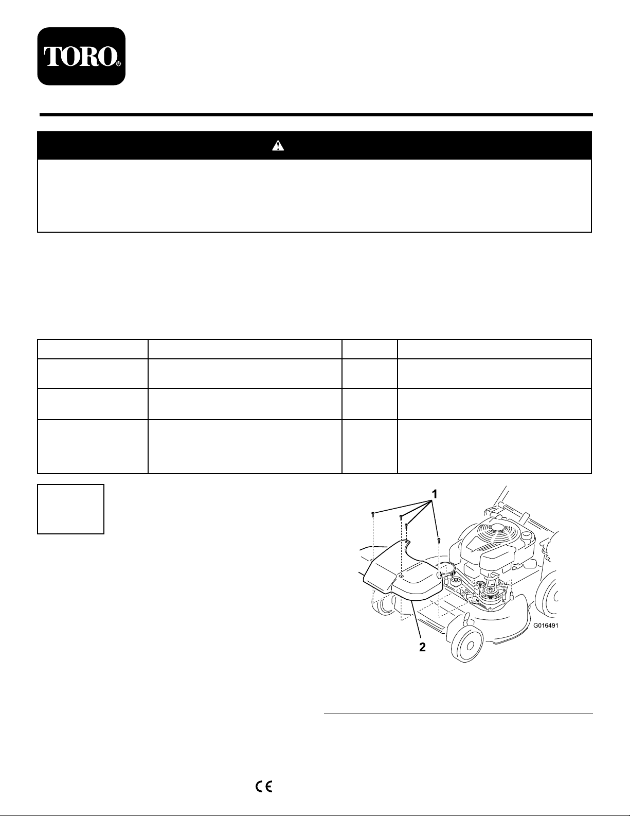
4.Removetheblade-drivesystemcoverfromthemachine
(Figure1).
Operator’ s Man ual
Registeratwww.T oro.com.
Figure1
1.Bolt(4)
5.Tipthemachineontoitsside,withtheairlterfacing
upward,untiltheupperhandlerestsontheground.
OriginalInstructions(EN)
PrintedintheUSA
AllRightsReserved
2.Blade-drivesystemcover
*3411-616*A
g016491
Page 2
Important:Tippingthemachinemaycausethe
fueltoleak.Fuelisammableandexplosive,and
cancausepersonalinjury.Runtheenginedryto
removethefuelwithahandpump;neversiphon
thefuel.
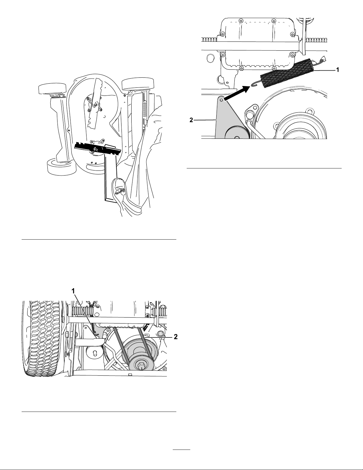
6.Useablockofwoodtoholdeachbladesteady(Figure
2).
g194726
Figure4
1.Brake-extensionspring2.Brakearm
Figure2
7.Removethetransmissionbeltandthetransmission
tensionspringfromthemachine(Figure3).
Note:Removingthetransmissionbeltandthe
transmissiontensionspringallowsaccesstothebrake
arm.
Figure3
g196361
g193793
1.Transmissiontension
spring
2.Transmissionbelt
8.Removethebrake-extensionspringfromthebrake
arm(Figure4).
2
Page 3
2
1
2
G019923
RemovingtheExistingBrake
ArmandBrakeCable
NoPartsRequired
Procedure
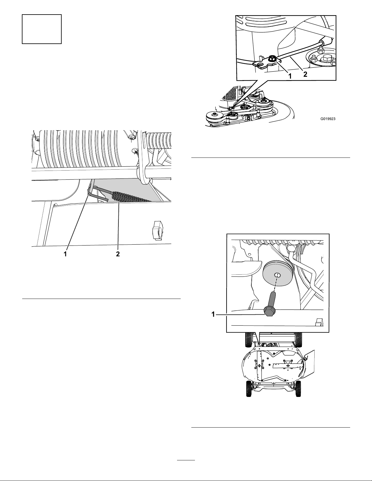
1.Removethebrakecablefromthebrake-armhook
(Figure5).
g019923
Figure6
Figure5
1.Brake-armhook2.Brakecable
2.Loosenthecable-clampscrewandslidethecableout
fromundertheengine(Figure6).
1.Cable-clampscrew
3.Removethebrakearmfromthemachine.
Note:Thebrakearmcanbemountedontothe
machinewithathread-formingscreworaboltanda
nut.
2.Brakecable
•Formachineswithathread-formingscrewthat
securesthebrakearmontothemachine:
Removethethread-formingscrew;retainandset
itaside(Figure7)
g194452
g195872
Figure7
1.Thread-formingscrew
•Formachineswithaboltandanutthatsecuresthe
brakearmontothemachine:
3
Page 4

Removetheboltandthenut;retainandsetthem
aside(Figure8andFigure9).
Important:Retainallhardwareforusein3
InstallingtheBrakeArmandBrakeCable(page
4).
g193781
Figure10
g194201
Figure8
6.Disconnectthebrakecablefromtheblade-controlbar;
retainandsetthepushnutaside(Figure11).
1.Bolt
g193932
Figure11
5.Cutandremovetheexistingcableties.
Figure9
1.Nut
4.Removethehardwarefromthebrakearm(Figure10).
1.Pushnut2.Brakecable
g194514
4
Page 5

Usethethread-formingscrewtosecurethebrake
armontothemachine(Figure7).
3
InstallingtheBrakeArmand
BrakeCable
Partsneededforthisprocedure:
1Brakearm
1Brakecable
1Rubberspacer
2
Cabletie
Procedure
1.Installtherubberspacerandthehardwarefromtheold
brakearmontothenewbrakearm(Figure12).
Important:Inspecttherubberfrictionwashersfor
excessivewear.Replacethewashersifnecessary.
Note:T orquethescrewto16to20N∙m(144to
176in-lb).
•Formachineswithaboltandanutthatsecuresthe
brakearmontothemachine:
Usetheboltandthenuttosecurethebrakearm
ontothemachine(Figure8andFigure9).
Note:T orquethenutto10to13N∙m(85to115
in-lb).
Note:Afterinstallation,thebrakearmshouldhavea
fullrangeofmotionwithaslightresistancecreatedby
thefrictionwashers.
5.Usethepushnuttoinstallthebrakecableontothe
blade-controlbar(Figure11).
6.Routethebrakecablethroughtheinsertbelowthe
cableclamp(Figure6).
7.Attachthebrakecabletothebrake-armhook(Figure
13).
Figure12
1.Rubberspacer
2.Guidetherubberspaceralongthehookuntilitisush
withtheplate.
3.Torquetheboltthatyoupreviouslyremovedinstep4
to10to13N∙m(85to115in-lb).
4.Attachthebrakearmtothemachine.
•Formachineswithathread-formingscrewthat
securesthebrakearmontothemachine:
g195893
g193739
1.Brake-armhook2.Brakecable
8.Pullthecablejackettoremoveslack(Figure14).
Note:Donotputtensiononthespring.
5
Figure13
Page 6

Figure14
1.Cableclamp2.Cablejacket
9.Markthebrakecable(Figure15),thenadjustthejacket
untilthereisapproximately3mm(1/8inch)ofslack
(Figure16).
10.Torquethecable-clampscrewto11to14N∙m(99to
121in-lb)tolocktheadjustmentinplace.
11.Attach2cabletiesattheindicatedlocationsshownin
Figure17.
g195540
g194372
Figure17
1.Markthecablehere
1.Cabletielocations
12.Attachthebrake-extensionspringtothebrakearm.
13.Installthetransmissionbeltandthetransmission
tensionspring(Figure3).
14.Installtheblade-drivesystemcover(Figure1).
15.Connectthespark-plugwiretothesparkplug.
g195615
Figure15
1.Slack—3mm(1/8inch)
g195616
Figure16
6
Page 7

Notes:
Page 8

 Loading...