

Page 1
FormNo.3407-663RevB
Long-RangeExit-SideLockoutKit
2226,4045,and4050DirectionalDrill
ModelNo.133-6314
Operator'sManual
FCCStatements
Introduction
15.19–TwoPartWarning
Theexit-sidelockouttransmitterandreceiveris
designedtoremotelystopandlockouttheuser
controlsofadirectionaldrill.
Readthisinformationcarefullytolearnhowtooperate
andmaintainyourmachineproperlyandtoavoid
injuryandequipmentdamage.Y ouareresponsible
foroperatingthemachineproperlyandsafely .
YoumaycontactT orodirectlyatwww.T oro.comfor
productandaccessoryinformation,helpndinga
dealer,ortoregisteryourproduct.
Thismanualidentiespotentialhazardsandhas
safetymessagesidentiedbythesafetyalertsymbol
(Figure1),whichsignalsahazardthatmaycause
seriousinjuryordeathifyoudonotfollowthe
recommendedprecautions.
Figure1
1.Safetyalertsymbol
ThisdevicecomplieswithPart15oftheFCCrules.Operation
issubjecttothefollowingtwoconditions:
(1)Thisdevicemaynotcauseharmfulinterferenceand
(2)Thisdevicemustacceptanyinterferencereceived,including
interferencethatmaycauseundesiredoperation.
15.21–UnauthorizedModication
NOTICE:Themanufacturerisnotresponsibleforany
unauthorizedmodicationstothisequipmentmadebytheuser.
Suchmodicationscouldvoidtheuser’sauthoritytooperate
theequipment.
15.105(b)–Note:
Thisequipmenthasbeentestedandfoundtocomplywith
thelimitsforaClassBdigitaldevice,pursuanttoPart15
oftheFCCRules.Theselimitsaredesignedtoprovide
reasonableprotectionagainstharmfulinterferenceina
residentialinstallation.Thisequipmentgenerates,usesand
canradiateradiofrequencyenergyand,ifnotinstalledand
usedinaccordancewiththeinstructions,maycauseharmful
interferencetoradiocommunications.However,thereis
g000502
noguaranteethatinterferencewillnotoccurinaparticular
installation.Ifthisequipmentdoescauseharmfulinterference
toradioortelevisionreception,whichcanbedeterminedby
turningtheequipmentoffandon,theuserisencouragedto
trytocorrecttheinterferencebyoneormoreofthefollowing
measures:
Thismanualuses2wordstohighlightinformation.
Importantcallsattentiontospecialmechanical
informationandNoteemphasizesgeneralinformation
worthyofspecialattention.
ThisproductcomplieswithallrelevantEuropean
directives.Fordetails,seetheseparate
product-specicDeclarationofConformity(DOC)
sheet.
Thisproductmaycontainmaterialthatmaybe
hazardoustohumanhealthandtheenvironment.In
compliancewithEUDirective2002/96/EConWaste
ElectricalandElectronicEquipment(WEEE):
•Donotdisposeoftheproductasunsorted
municipalwaste.
•Thisproductshouldberecycledinaccordance
withlocalregulations.Contactlocalauthoritiesfor
detailedinformation.
•Thisproductmaybereturnabletothedistributor
forrecycling.Contactyourdistributor/dealerfor
details.
©2018—TheT oro®Company
8111LyndaleAvenueSouth
Bloomington,MN55420
Registeratwww.T oro.com.
•Reorientorrelocatethereceivingantenna.
•Increasetheseparationbetweentheequipmentandreceiver.
•Connecttheequipmentintoanoutletonacircuitdifferent
fromthattowhichthereceiverisconnected.
•Consultthedealeroranexperiencedradio/TVtechnicianfor
help.
IndustryCanadaStatement
ThisdevicecomplieswithCanadianRSS-210.
Theinstallerofthisradioequipmentmustensurethatthe
antennaislocatedorpointedsuchthatitdoesnotemitRFeld
inexcessofHealthCanadalimitsforthegeneralpopulation;
consultSafetyCode6,obtainablefromHealthCanada’s
websitewww.hc-sc.gc-ca/rpb.
ThisdevicecomplieswithIndustryCanadalicence-exempt
RSSstandard(s).Operationissubjecttothefollowingtwo
conditions:(1)thisdevicemaynotcauseinterference,and(2)
thisdevicemustacceptanyinterference,includinginterference
thatmaycauseundesiredoperationofthedevice.
OriginalInstructions(EN)
PrintedintheUSA.
AllRightsReserved
*3407-663*B
Page 2

Safety
Improperlyusingormaintainingthisequipment
canresultininjury.Toreducethepotentialfor
injury,complywiththesesafetyinstructions.Toro
testedthisequipmentforreasonablysafeservice;
however,failuretocomplywiththefollowing
instructionsmayresultinpersonalinjury.
Toensuremaximumsafety,bestperformance,
andtogainknowledgeoftheproduct,itis
essentialthatyouandanyotheroperatorreadand
understandthecontentsofthismanualbefore
usingthisproduct.Payparticularattentionto
thesafetyalertsymbol(Figure1),whichmeans
Caution,Warning,orDanger—“personalsafety
instruction.”Readandunderstandtheinstruction
becauseithastodowithsafety.Failuretocomply
withtheinstructionmayresultinpersonalinjury .
•Failuretoabidebytheseprecautionsmayresultin
equipmentfailureandpersonalinjury.
•Useandmaintainproperwiring.Improper,loose,
andfrayedwiringcancausesystemfailure,
equipmentdamage,andintermittentoperation.
•Changesormodicationsmadetoequipmentnot
expresslyapprovedbythemanufacturerwillvoid
thewarranty .
•Owner/operatorsoftheequipmentmustabide
byallapplicableFederal,State,andLocallaws
concerninginstallationandoperationofthe
equipment.
•Makesurethatthemachineryandsurrounding
areaisclearbeforeoperating.Donotactivatethe
remotecontrolsystemuntilcertainthatitissafe
todoso.
•Turnoffthehandheldremoteandremove
powerfromthebaseunitbeforeattempting
anymaintenance.Thiswillpreventaccidental
operationofthecontrolledmachinery.
•PowerisremovedfromtheBaseUnitbydetaching
the12-pincablefromthebaseunitconnectorP1,
orbyremovingthesourcepowerfromthecircuit.
•Useadampclothtokeepunitsclean.Remove
mud,concrete,dirt,etc.afterusetoprevent
obstructingorcloggingthebuttons,levers,wiring,
andswitches.
•Donotallowliquidtoenterthehandheldorbase
unitenclosures.Donotuseahighpressure
washertocleantheequipment.
•Disconnecttheradiobaseunitbeforeweldingon
themachine.Failuretodisconnectthebaseunit
mayresultindestructionofordamagetothebase
unit.
•Operateandstoreunitsonlywithinthespecied
operationandstoragetemperaturesdenedinthis
document.
2
Page 3
Setup
InstallingtheReceiver
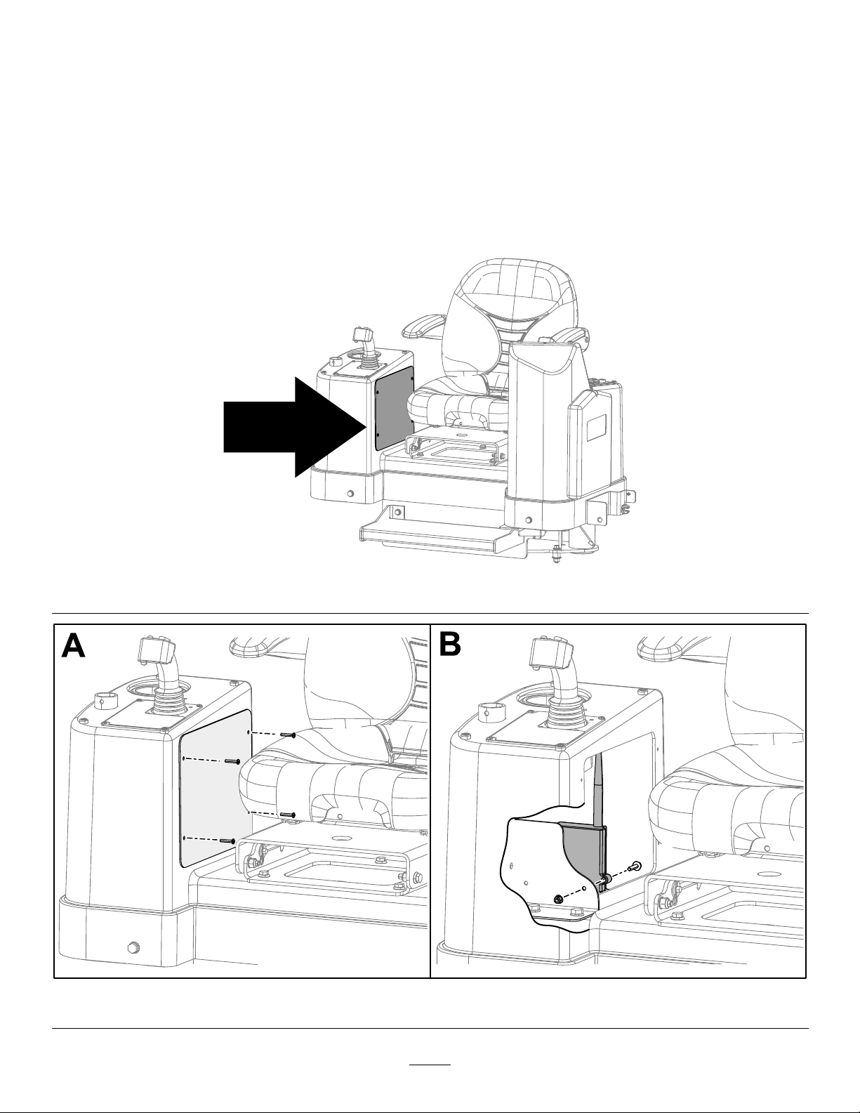
InstallingtheReceiveronthe4045and4050Machines
1.Movethemachinetoalevelsurface,shutofftheengine,andwaitforallmovingpartstostop.
2.Removethepanelonthecontroltowernexttotheoperator’sseat(BoxAofFigure3).
3.Installthereceiveronthebracketusing2boltsand2nuts(BoxBofFigure3).
4.Installthepanelonthecontroltower.
Figure2
g243872
Figure3
3
g243871
Page 4

InstallingtheReceiveronthe4050MachinewithaCab
1.Movethemachinetoalevelsurface,shutofftheengine,andwaitforallmovingpartstostop.
2.Removetheleftcontrolpanelcover(BoxesAandBofFigure4).
3.Locatethebracketandinstallthereceiverusing2boltsand2nuts(BoxesCandDofFigure4).
4.Installthecontrolpanelcover.
Figure4
4
g243813
Page 5

InstallingtheReceiveronthe2226Machine
1.Movethemachinetoalevelsurface,shutofftheengine,andwaitforallmovingpartstostop.
2.Removetheboltsandwashersonthebackofthedisplay(BoxBofFigure5).
3.Removethebackpanelofthedisplay(BoxCofFigure5).
4.Removethe2boltsandwashersontheinsideofthedisplaybox(BoxDofFigure5).
5.Removetheremainingboltsofthecontrolpanelcover(BoxEofFigure5).
6.Liftthecontrolpanelcoveroutoftheway(BoxFofFigure5).
7.Installthereceiverusing2boltsand2nuts(BoxGofFigure5).
8.Installtheantennaofthereceiverontheoutsideofthecontrolpanelbox(BoxHofFigure5).
9.Installthecontrolpanelcoveranddisplaypanel.
Figure5
5
g243857
Page 6

ProductOverview
Controls
Exit-Side-LockoutSystem
Theexit-side-lockoutsystemprovidestheindividuals
workingaroundthemachinewithameanstodisable
thedrillpipefromrotatingandthrusting.
•Placingawiperonthedrillpipe
•Whenthehandheldtransmitteroperatoridenties
aproblemrequiringimmediateshutdownofdrilling
Whenitissafetoresumedrilling,theindividual
holdingthetransmittercanpresstheUNLOCKDRILL
(ON)button.Thisbuttonsendsasignaltothereceiver
thatallowsthemachineoperatortoresetthesystem
andrestorethethrustandrotaryfunctions.
Thissystemconsistsofareceivermountedonthe
machineandatransmitter(Figure6)thatmustbe
heldbyadesignatedindividualworkingaroundthe
machine.
Figure6
1.TXindicatorlight5.A1indicatorlight
2.RXindicatorlight6.A2indicatorlight
3.ERindicatorlight
4.BAindicatorlight
LabelFunction
TXTransmit
RXReceive
ERError
BALowBattery
A1Auxiliary1
A2Auxiliary2
7.Onbutton
8.Offbutton
Specications
HandheldUnit
Batteries3AAA
Autoshutdown
Lowbatterywarning3.2Vandbelow
LowbatteryshutdownAt3.2VtheBAindicator
Operatingtemperature-20to55degreesC(-4to131
Storagetemperature-40to55degreesC(-40to
Radiofrequency
RadioRFpower50mW
RadiolicenseNotrequired
Modulation
AntennaInternal
g038050
BaseUnit
Radiofrequency
RadioRFpower100mW
RadiolicenseNotrequired
Modulation
AntennaExternal
Operatingtemperature-20to55degreesC(-4to131
Storagetemperature-40to55degreesC(-40to
After2hoursofinactivity
lightwillashrapidlyfor30
secondspriortoshutdown.
degreesF)
131degreesF)
2405to2480MHz
DSSS
2405to2480MHz
DSSS
degreesF)
131degreesF)
Theindividualholdingthetransmittercanpushthe
LOCKDRILL(OFF)buttontostopthedrillrotationand
thrust.Thisisprimarilyusedtostop/lockoutthedrill
operationsinthefollowingsituations:
•Wheninstallingorremovingadrillheadorreamer
•Wheneversomeoneneedstoapproachthedrill
pipeorheadanywhereinfrontofthemachine
6
Page 7

Operation
HandheldIndicatorLights
Thefollowingtableliststhevariousstatesofthe
indicatorlightsonthehandheldtransmitter(Figure6)
andtheirmeanings:
IndicatorLightState
TheTXindicatorlightisdim
andblinkingrapidly .
TheTXindicatorlightisbright
andblinkingrapidly .
TheRXindicatorlightisbright
andblinkingrapidly .
TheERindicatorlightislit
solid.
TheBAindicatorlightis
blinkingslowly .
Meaning
Thehandledunitis
transmittingtothereceiver.
Abuttonisactiveonthe
handheldunit.
Thehandheldunitisreceiving
transmission.
Thereisanerrorwiththe
transmission.
Thebatteriesarelow.See
ReplacingtheTransmitter
Batteries(page7)
ReplacingtheTransmitter Batteries
1.Loosenthe4boltssecuringthebatterycover
(Figure7).
g023888
Figure8
1.Handheldtransmitter2.Batterycover
3.Removetheexistingbatteries.
4.Install3new,AAAbatteriesintheorientation
showninFigure9.
Important:Ensurethatyouinstallthe
batteriesinthecorrectpolarityorientationor
youcoulddamagethetransmitter.
Figure7
1.Handheldtransmitter3.Bolts
2.Batterycover
2.Removethecover(Figure8).
g023889
Figure9
1.Handheldtransmitter2.AAAbatteries
g023887
5.Replacethecoverandsecureitwiththebolts
previouslyremoved.
Tightentheboltsenoughtoensurethatthe
sealinggasketiscompressed,butdonotover
tightenthem.
7
Page 8

AssociatingtheHandheld TransmitterwiththeBase Unit
Ifthehandheldtransmittereverstopscommunicating
withthebaseunit,orifyoureplaceitwithanew
transmitter,youneedtoassociatethetransmitterto
thebaseunitasfollows:
1.Ensurethatthemachineisturnedoff.
2.Ensurethatthehandheldtransmitterisnot
active(i.e.,nolightsareon).
Important:Ifyoudonotpressthisbutton
within2seconds,youwillhavetostartthis
procedureoveragain.
7.ContinueholdingtheOFFbuttonandturnonthe
machinetopowerthebaseunit.
Thebaseunitandhandheldestablisha
communicationlinkwhileyouholdthebutton.
Oncetheprocessiscomplete,theyellowlight
turnsoff,theredlightbeginsashing,andthe
greenlightilluminates.Alllightsremainas
mentioneduntilyoureleasethebutton.
8.ReleasetheOFFbutton.
3.Standneartherearcontrolpanelofthemachine.
4.SimultaneouslypressandholdtheONandOFF
buttons.
Allofthelightswillilluminate.
5.ContinueholdingthebuttonsuntiltheTXlight
beginsashing.
6.ContinueholdingtheONandOFFbuttonsand
turnonthemachinetopowerthebaseunit.
Thebaseunitandhandheldestablisha
communicationlinkwhileyouholdthebutton.
Oncetheprocessiscomplete,allofthelights
willash.
7.Releasethebuttons.
DisassociatingallHandheld TransmittersfromtheBase Unit
Important:Completingthisprocedurewill
disassociatealltransmittersfromthebaseunit,
whichwillneedtobeassociatedagainbeforethey
willfunction.
Theredlightturnsoffandthegreenlightashes
forafewseconds.
1.Ensurethatthemachineisturnedoff.
2.Ensurethatthehandheldtransmitterisnot
active(i.e.,nolightsareon).
3.Standneartherearcontrolpanelofthemachine.
4.SimultaneouslypressandholdtheONandOFF
buttons.
Thegreenlightilluminates.
5.Continueholdingthebuttonsuntiltheyellow
lightbeginsashing,thenreleasethebuttons.
Theredlightbeginsashingallowingyou2
secondstopressthenextbutton.
6.PressandholdtheOFFbutton
Theredlightturnsoffandthegreenandyellow
lightsilluminate.
8
 Loading...