

SEIKAKU TECHNICAL GROUP
NPD-TO-1102001
8
PHFUA102-20110400017
A3 A4 A5
TAP20A/20T/40A/40T
0.016KG/1
NH00149 1:2
TAP20A/20T/40A/40T TOPP PRO_V1.0
NF03559
-RS
TOPP PRO
LIMITED
APR.06.2011
4
OUTDOO RS
INDOO RS
SPEAKER
TAP20A/20T/40A/40T
OUTDOO RS
INDOO RS
SPEAKER
NF03559-1.0
OUTDOO RS & INDO O RS
SPEAKER
OUTDOO RS & INDO O RS
SPEAKER
11
15
OUTDOO RS & INDO O RS
SPEAKER
Guarantee
OUTDOO RS & INDO O RS
SPEAKER
10
1. INTRODUCTION ................................................................4
2. USEFUL TIPS.....................................................................4
3. USEFUL DATA ...................................................................4
4. CONTROL ELEMENTS.........................................................5
5. CONNECTION DIAGRAM....................................................6
6. INSTALLATION DESCRIPTION.............................................8
7. BLOCK DIAGRAM....................... ......................................10
8. FREQUENCY RESPONSE DIAGRAM.....................................11
9.TECHNICAL SPECIFICATION...............................................12
10. GUARANTEE...... ...........................................................14
4
OUTDOO RS & INDO O RS
SPEAKER
OUTDOO RS & INDO O RS
SPEAKER
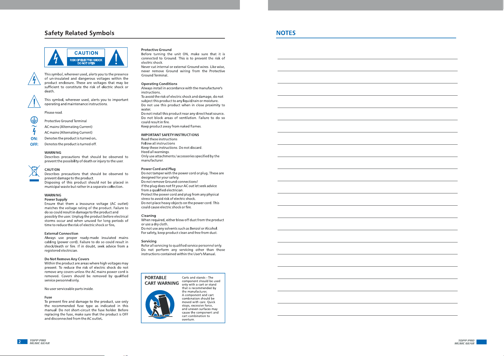
Introduction
TAP20A/20T/40A/40T are designed for indoor and outdoor installation and
public address system. They provide quality performance and alternative
two models, including speaker cabinet with transformer and active speaker
cabinet. Further more, we offer optional metal rotatable mounting bracket,
thus you can install TAP SERIES speakers on wall easily. This new compact
speaker series meet every demand for restaurants super market, shopping
mall, pubs and so on.For TAP40T, it is equipped with IP44, it can be used in
various outdoor applications and situations.
Enjoy your TAP SERIES speaker cabinet and make sure that read this
manual carefully before operation.
Useful Tips
Speakers should be placed in a position that allows for unobstructe sound
projection. In many instances is beneficial for speakers to be elevated on
tripod stands to achieve maximum dispersion and reach.
*Use professional advice or service when hanging and installing speakers.
Please take precautions to secure them to prevent them from falling and
hurting someone. Care should be taken as to not damage the cabinet or
its components. Please comply with all pertinent Regulations.
*Use quality cables. Using quality cables will ensure the best possible sound.
*For best results match the speakers to a good amplifier that matches the
wattage & impedance of your speakers. Proper amplification power results
in good quality audio & longer component life. Check out the power
requirement for your cabinet.
*Avoid pointing a microphone directly at an amplified speaker doing so,
could cause feedback possibly damaging speaker components and your
hearing.
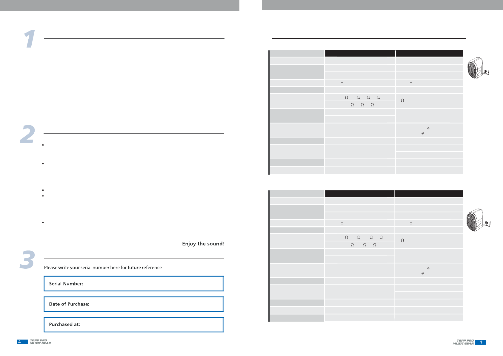
Useful Data
Technical Specification
Model
System Type
Speaker
SPL at 1m/1w
Frequency Response(-10dB)
Impedance
Power Rating
Connector
External Controls
Power Supply
Dimensions
Weight
Model
System Type
Speaker
SPL at 1m/1w
Frequency Response(-10dB)
Impedance
Power Rating
Connector
External Controls
Power Supply
Dimensions
Weight
IP Grade
Speaker cabinet with transformer
3''(77*77mm)paper cone speaker
0.8''(20.4mm)voice coil diameter
85 dB( 3dB)
132Hz-20KHz
70V 245 /500 /1K /2K
100V 500 /1K /2K
70V 20W/10W/5W/2.5W
100V 20W/10W/5W
Wiring Terminal
Power selective switch
115*107*175mm
1.12kg/2.47lbs
Speaker cabinet with transformer
4''(106mm)paper cone speaker
1''(25.4mm)voice coil diameter
90 dB( 3dB)
76Hz-18KHz
70V 122 /250 /500 /1K
100V 250 /500 /1K
70V 40W/20W/10W/5W
100V 40W/20W/10W
Wiring Terminal
Power selective switch
136*140*206mm
2.3kg/5.07lbs
IP 44
TAP20T
TAP40T
9
TAP20A
Active speaker cabinet
3''(77*77mm)paper cone speaker
0.8''(20.4mm)voice coil diameter
85 dB( 3dB)
132Hz-20KHz
4
20W (RMS)
Input-RCA and 6.3 Balanced/
Output-link 6.3 Jack
Volume control/Power switch
220V-240V/50Hz
110V-120V/60Hz
115*107*175mm
1.342kg/2.96lbs
TAP40A
Active speaker cabinet
4''(106mm)paper cone speaker
1''(25.4mm)voice coil diameter
90 dB( 3dB)
76Hz-18KHz
4
30W (RMS)
Input-RCA and 6.3 Balanced/
Output-link 6.3 Jack
Volume control/Power switch
220V-240V/50Hz
110V-120V/60Hz
136*140*206mm
2.40kg/5.29lbs
3
OUTDOO RS & INDO O RS
SPEAKER
OUTDOO RS & INDO O RS
SPEAKER
8
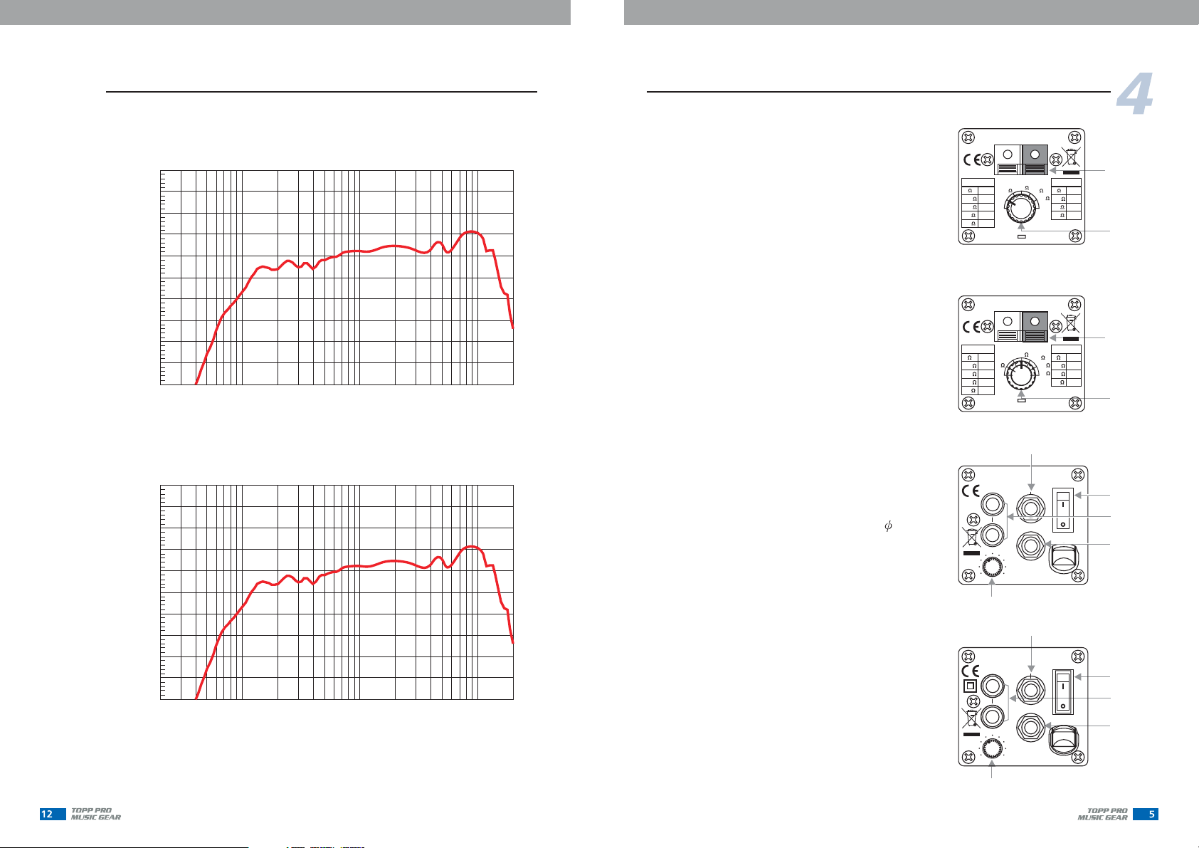
Frequency Response Diagram
TAP40A
+110
+105
+100
+95
d
+90
B
+85
S
P
+80
L
+75
+70
+65
+60
20 20k50 100 200 500 1k 2k 5k 10k
Hz
TAP40T
+110
+105
+100
+95
d
+90
B
+85
S
P
+80
L
+75
+70
+65
+60
20 20k50 100 200 500 1k 2k 5k 10k
Hz
Control Element
REAR PANEL
1- Input Connection
Use push-button for fixed installation.
The Positive connection is usually marked
with(+),orRedpush-button. Use it to
connect the amplifier output ( + ).
The Negative connection is usually marked
with(-),orBlack push-button. Use it to
connect the amplifier output(-).
2- Power Selections
With this rotary switch, it is possible
to select the power level
from 2.5W minimum to 20W maximum,
TAP40T from 5W minimum to 40W
maximum
for two different constant
voltages 70V or 100V. In Off position
the speaker system is disconnected
from the Line. For TAP40T, the bypass
is activated in 6 Ohms position.
3- Balanced Input
Use this socket to input signal with a
6.3 cable.
4- ON/OFF switch
Use this switch to switch on/off power
supply.
5- Stereo Input
It is used to input stereo signal.
6- LINK
It is used for outer signal output and be
connected with other active speaker
cabinets.
7- Volume Control
It is used to adjust the main volume.
of TAP20T
245
500
1K
2K
122
250
500
1K
70V
W
20W
10W
5W
2.5W
70V
W
40W
20W
10W
5W
STEREO
INPUT
(7)
STEREO
INPUT
(7)
TAP20T
500
245
1K
OFF
TAP40T
122
OFF
250
6
(3)
TAP20A
BALANCED
INPUT
L
LINK
R
MAX POWER:40W
AC 220-240V/50Hz
MAXMIN
(3)
TAP40A
BALANCED
INPUT
L
LINK
R
MAX POWER:50W
220-240V ~50Hz
MAXMIN
100V
2K
500
1K
2K
(1)
W
20W
10W
5W
(2)
100V
500
250
1K
500
1K
(1)
W
40W
20W
10W
(2)
ON
(4)
(5)
OFF
ON
(6)
(4)
(5)
OFF
(6)
OUTDOO RS & INDO O RS
SPEAKER
OUTDOO RS & INDO O RS
SPEAKER
5
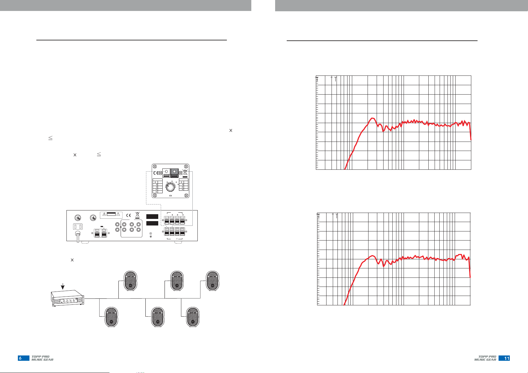
Connection Diagram
LEVEL DISTRIBUTION SYSTEM FOR TAP20T
Level distribution system only controls "T" model. TAP20T have built-in transformer
of 70/100V , can connect many speakers to one channel, and only need one
amplifier. The output terminal "com/-''stands for negative polar, terminal
"70V/100V/+" stands For positive. The red speaker terminal stands for positive,
black stands for negative. Please connect amplifier to speaker right, incorrect
connection may cause damage to amplifier and speaker. Finally set your
desired output power ,see picture A to adjust band switch to meet your need,
i
n this case, the total power of all the speakers can't exceed the nominal power
of amplifier. One 80W amplifier channel can drive 8 speakers of 10W, i.e. 10 8
=80 80W). For safety, the total power of all the speakers should be less than
3/4 nominal power of amplifier. (One 80W amplifier channel can drive 6 speakers
of 10W, i.e. 10 6=60W 80W).
amplifier
TAP 20T
70V
500
W
245
OFF
20W
245
10W
500
5W
1K
2.5W
2K
ACFUSE
DCFUSE
T1A/250V
S
S
U
U
E
E
F
F
ACOUTLET
110V/60Hz10A
ACIN 110V~60Hz
POWERCONSUMPTION:80W
T6.3A/250V
S
S
U
U
E
E
F
F
DC12V 5A
CAUTION
RISKOFELECTRIC SHOCK
RISKOFELECTRIC SHOCK
DONOTOPEN
DO
CAUTION: SHOCK HAZARD - DO NOT OPEN
RISKOF FIRE-REPLACE FUSE AS MARKED.
+
NOTOPEN
L
R
CD TAPE
RECOUT
MODEL
AUX
SERIAL
TUNER
COM
COM
(A)Figure
6 10 WATT=60 WATT TOTAL LOAD ON AMPLIFIER
INPUT
AMPLIFIER
TYPICAL 80 WATT
70V OUTPUT
10WATT TAP
10 WATT TAP
10WATT TAP
100V
W
1K
2K
20W
500
10W
1K
5W
2K
OUTPUT
4
8 16
70V
100V
COM
OUTPUT
10WATT TAP
40WATT TAP
10WATT TAP
Frequency Response Diagram
+110
+105
+100
+95
d
+90
B
+85
S
P
+80
L
+75
+70
+65
+60
20 20k50 100 200 500 1k 2k 5k 10k
+110
+105
+100
+95
d
+90
B
+85
S
P
+80
L
+75
+70
+65
+60
20 20k50 100 200 500 1k 2k 5k 10k
8
TAP20A
Hz
TAP20T
Hz
(B)Figure
OUTDOO RS & INDO O RS
SPEAKER
OUTDOO RS & INDO O RS
SPEAKER
7
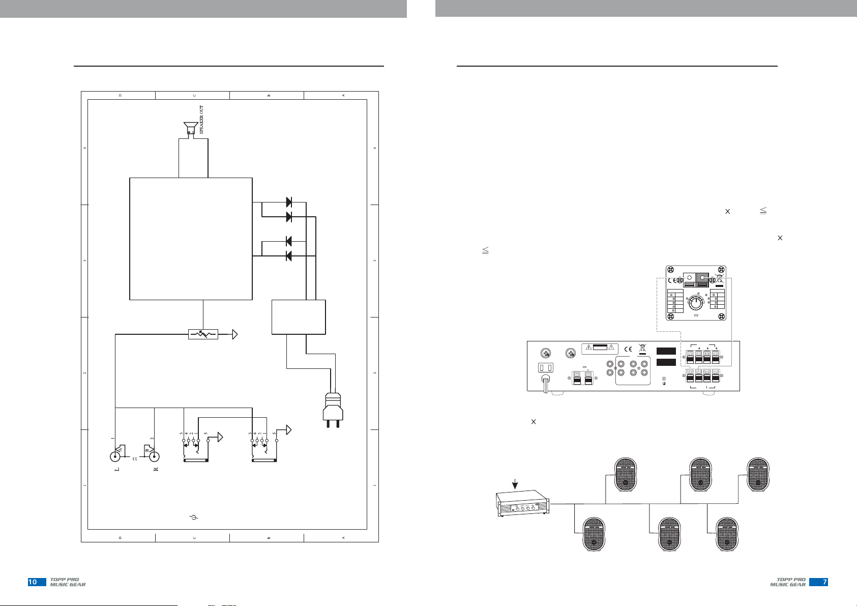
Block Diagram
TAP20A/40A BLOCK DIAGRAM
CLASS-D AMP
TRANSFORMER
Connection Diagram
LEVEL DISTRIBUTION SYSTEM FOR TAP40T
Level distribution system only controls "T" model. TAP40T have built in transformer of
70/100V , can connect many speakers to one channel , and only need one amplifier.
amplifier
The output terminal "com/-'' stands for negative polar, terminal "70V/100V/
+" stands For positive. The red speaker terminal stands for positive, black stands
for negative. Please connect amplifier to speaker right, incorrect connection may
cause damage to amplifier and speaker. Finally set your desired output power, see
picture C to adjust band switch to meet your need, i
all the speakers can't exceed the nominal power of amplifier.
One 320W amplifier channel can drive 8 speakers of 40W, i.e. 40 8=320 320W).
For safety, the total power of all the speakers should be less than 3/4 nominal power
of amplifier. (One 320W amplifier channel can drive 6 speakers of 40W, i.e. 40 6=
240W 320W).
ACFUSE
DCFUSE
T6.3A/250V
S
S
U
U
E
E
F
F
DC12V 5A
CAUTION
RISKOFELECTRIC SHOCK
RISKOFELECTRIC SHOCK
DONOTOPEN
DO
CAUTION: SHOCK HAZARD - DO NOT OPEN
RISKOF FIRE-REPLACE FUSE AS MARKED.
+
NOTOPEN
L
R
RECOUT
AUX
CD TAPE
()Figure C
TUNER
T1A/250V
S
S
U
U
E
E
F
F
ACOUTLET
110V/60Hz10A
ACIN 110V~60Hz
POWERCONSUMPTION:80W
n this case, the total power of
TAP40T
70V
W
40W
122
20W
250
10W
500
5W
1K
MODEL
SERIAL
100V
122
OFF
6
COM
COM
W
250
500
40W
250
1K
20W
500
10W
1K
OUTPUT
4
8 16
70V
100V
COM
OUTPUT
5
RCA INPUT
6.3 JACK INPUT
LINK
AC SOCKET
6 40 WATT=240 WATT TOTAL LOAD ON AMPLIFIER
INPUT
AMPLIFIER
TYPICAL 320 WATT
70V OUTPUT
40WATT TAP
40 WATT TAP
40WATT TAP
()Figure D
40WATT TAP
40WATT TAP
40WATT TAP

OUTDOO RS & INDO O RS
SPEAKER
OUTDOO RS & INDO O RS
SPEAKER
6
Installation Description
Note:
Commercial audio installation system must conform to local building
laws. When install speaker on wall or ceiling, please consult a building designer
with a license or a professional engineer. The corporation won't be responsible
for the improper installation or damage because of not conforming to installation
description.
Installation procedure of the bracket(bracket
TAP40A/40T)
eye.
Step 1:
support the weight of the cabinet.
Step 2:
Step 3:
to connect two brackets.
(3)
(1)
is very simple & convenient, the appearance is pleasing to the
Fasten the bracket on the wall with screws. The wall material must
Place the body of cabinet in bracket and lock the screws tightly.
Use screw bracket and bracket and use steel rope
(3) lock (1) (2) (4)
(2)
(1)
CS-2 is for TAP20A/20T, CS-3 for
(2)
Installation Description
Every reflection will loss the energy. When the acoustic hit the reflection surface,
the room will be filled with random reflected acoustic wave. The music and address
will be complex. It is recommended that install more speakers and make the
volume of speakers lower to reduce the reverberation in high reverberating room.
ONE LOUD SPEAKER
(Figure A)
Speaker coverage range: Direct the center axile of the speaker to the flat surface
of receiving area. The speakers of 90 90 series can spread the speaker tone to all
the directions at the axile of 45 . If you use the speakers in a large room, you can
divide the room to some zones. Then decide the installing location of the speakers .
MULTIPLE QUIET SPEAKERS
(Figure B)
6
(4)
INDOOR INSTALLATION DESCRIPTION:
TAP series speakers are designed specially for fixing and using in different
circumstances. The property of speakers may be different due to different
circumstances. There is an acoustic surface (wall, floor and ceiling) in a closed
room, so the acoustic indoor will turn complex. When acoustic wave hits the
surface, a part of acoustic energy is others are absorbed.
Reflection and absorption are depending on the frequencies of acoustic wave
and angle of hitting surface. When operate the cabinet, both man& furniture
can absorb the acoustic energy. Please note the position of man and furniture
when installing. Reverberation is the results of the reflected acoustic wave
continue bouncing between the surfaces.
reflected,
45
45
45
45
HORIZONTAL
45
45
VERTICAL
45
45
 Loading...