

Page 1
SEIKAKU TECHNICAL GROUP
NF03570
PHFAA102-20110400029
-RS
SPA-12 _V1.0
SPA-12
0.04kg/1
NH00149 1:2 / NH00231 1:4
LIMITED
A3
:
10
SH-201104005
A4
A5
5
APR.14.2011
Page 2
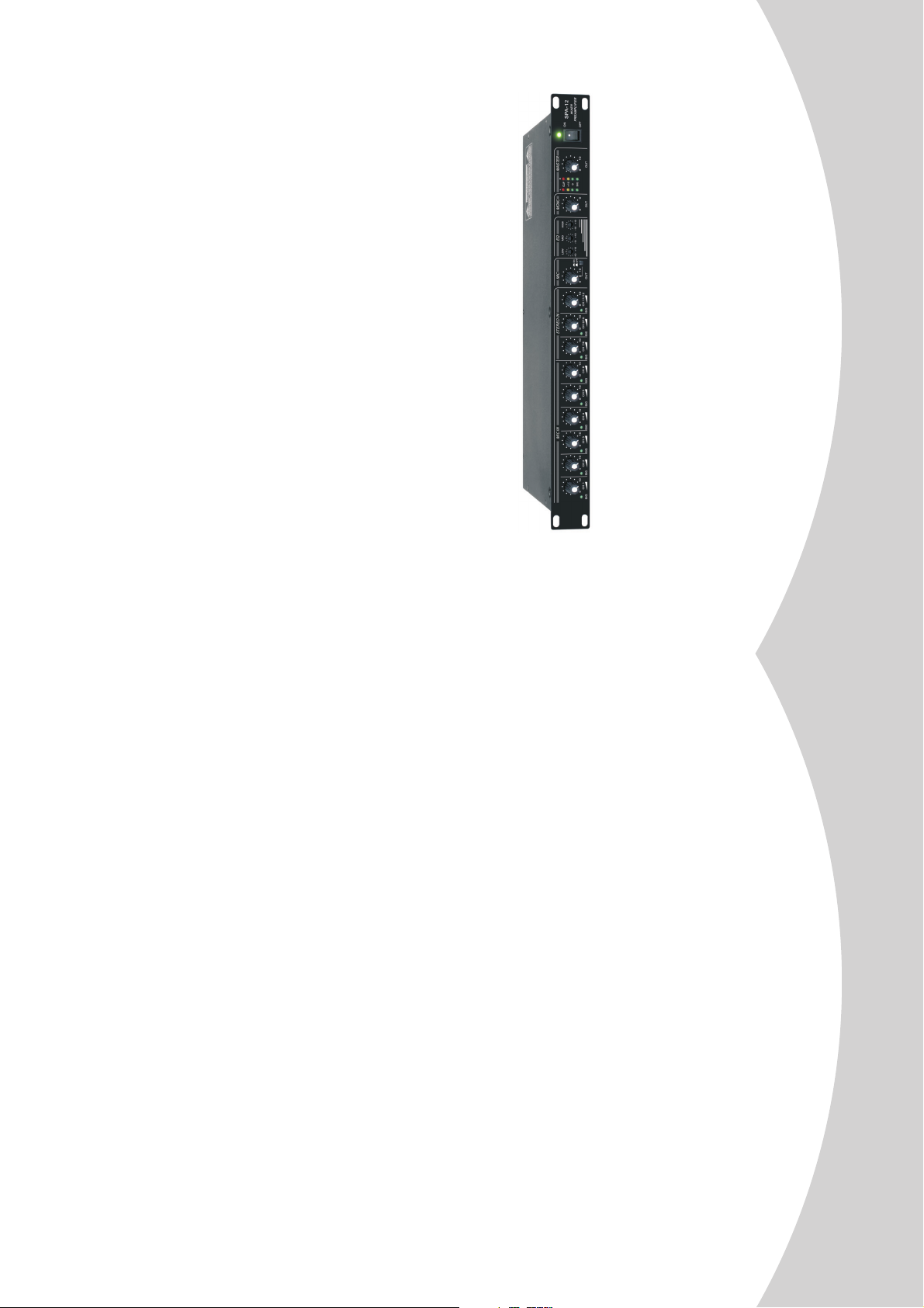
User's Manual
MIXER PREAMPLIFIER
Page 3

PROFESSIONAL MIXER PREAMPLIFIER
Whattodo
TROUBLE SHOOTING
Likely Cause
Speaker not connected to
Symptom
1
Verify that speaker is connected and that the circuit is on
active AC power
No sound
Switch on power and verify that power Led is on
*Re-seat the power cable at both ends;
*Substitute a known-good power cable
*Check fuse & replace with same type "spare fuse in holder"
Power not switched on
Speaker power cable is faulty
or improperly connected.
Blown fuse
come on
AC power but won't
connected to working
No sound, speaker is
1
2
3
*Check if the signal LED indicators are lit on
*Verify that the tape or CD is playing;
*Use headphones to verify that the instrument is actually sending
Signal source (mixer, Amp
instrument) is not sending
No sound
4
an audio signal
Speaker comes on
7
The EON does not supply phantom power. Switch to a dynamic
*Disconnect and re-seat signal cables;
*Replace suspected cable with a known-good cable
Faulty cables & connections
14
microphone, use a battery powered microphone (if possible),
use an external phantom power supply for condenser type
Microphone requires
phantom power
No sound with
to MIC /LINEinput
microphone connected
15
microphones.
*Reduce the output level of the source;
*Turn down the level controls on the speaker;
*Use additional EON speakers
Excessive input signal, trying
to exceed the capabilities of
the speakers
is lit most of the time
and veryloud,LIMIT light
Signal sounds distorted
17
for your mixer and adjust controls as needed;
*Make sure that the MIC / LINE switch is in the LINE(disengaged)
*Reduce the level settings at speaker, Review the Owner's Manual
*Input sensitivity(gain);
*Channel faders;
Improper gain structure
mixer controls are
at very low settings.
Lots of hiss in sound,
*Master faders;
equipment to drive your EON speakers.
*"lift" audio ground by using XLR/F to XLR/M adapter on one end
*Re-route audio cables away from AC power and lighting cables.
*Use the balanced outputs(if available)of your mixer or source
Improper A/Cgounding,
ground loops
Excessively long unbalanced
output to a balanced output.
*Use"DI"(direct injection) box to convert unbalanced equipment
cable run
Hum or Buzz
Reduce the INPUT level controls and increase the output level
of your source devices.
Improper system gain
structure
position;
17
INDEX
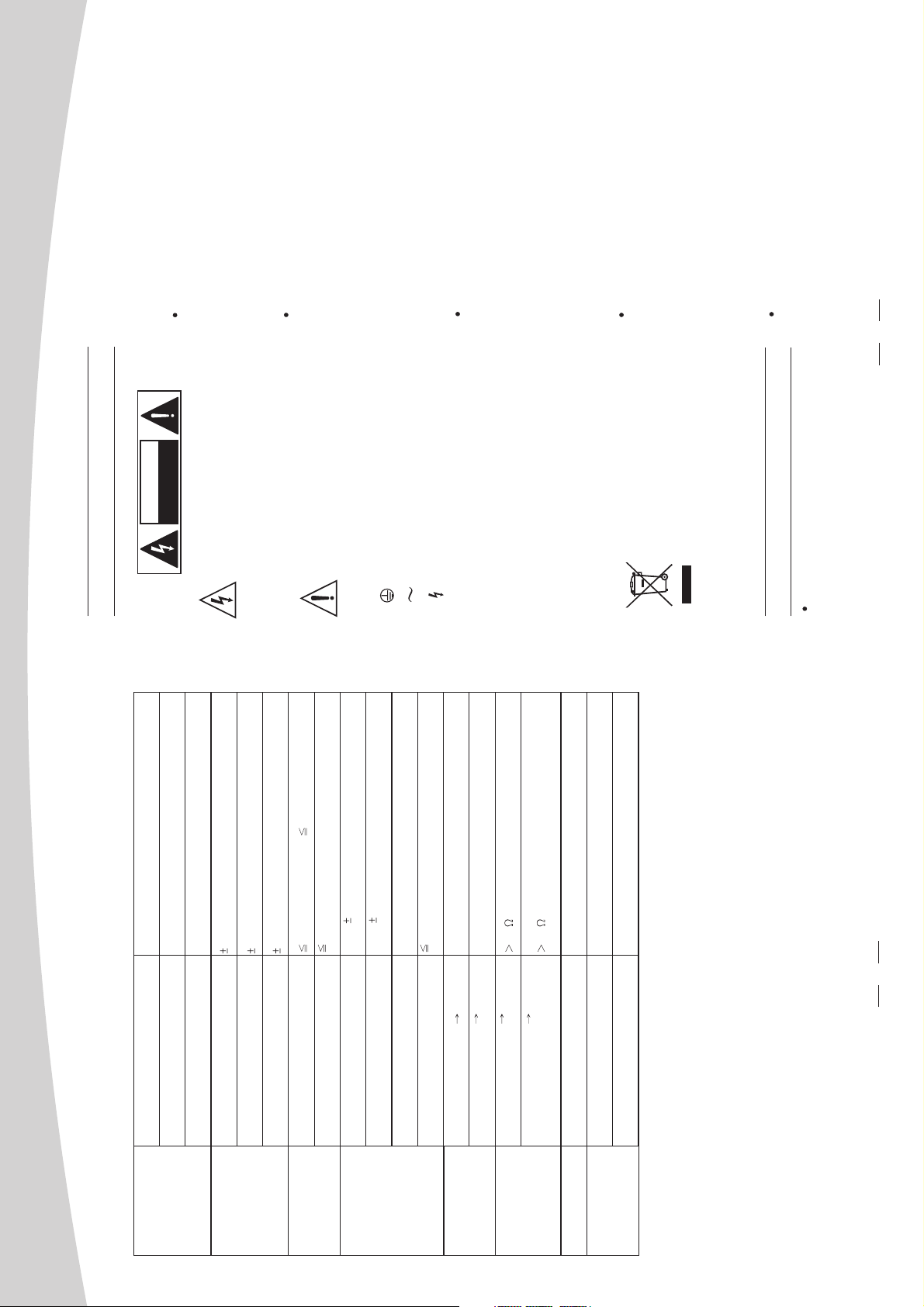
SAFETY RELATED SYMBOLS
01
WARNING
IMPORTANTSAFETY INSTRUCTION
02
03
INTRODUCTION
04
INSTALLATION & CONNECTION
CONTROL ELEMENTS
05
06
BLOCK DIAGRAM
TECHNICAL SPECIFICATION
07
08
TROUBLE SHOOTING
09
Page 4
PROFESSIONAL MIXER PREAMPLIFIER
Unplug this apparatus during lightning
storms or when unused for long periods
of time.
CAUTION
The external wiring connected to the output
External Connection
DO NOTOPEN
RISK OFELECTRIC SHOCK
The symbol is used to indicate that
hazardous live terminals requires installation
by an instructed person, or the use of ready-
made leads or cords.
some hazardous live terminals are
involved within this apparatus, even
under the normal operating conditions.
There are maybe some areas with high
Do not Remove any Cover
The symbol is used in the service
documentation to indicate that specific
voltages inside, to reduce the risk of electric
shock, do not remove any cover if the power
component shall be only replaced by
the component specified in that
supply is connected.
The cover should be removed by the qualified
Documentation for safety reasons.
Protective grounding terminal.
No user serviceable parts inside.
personnel only.
Alternating current /voltage.
To prevent a fire, make sure to use fuses
with specified standard (current, voltage,
type). Do not use a different fuse or short
circuit the fuse holder.
Before replacing the fuse, turn OFF the
apparatus and disconnected the power
Fuse
source.
Make sure to connect the protective
grounding to prevent any electric shock
Protective Grounding
before turning ON the apparatus.
Never cut off the internal or external pro-
tective grounding wire or disconnect the
wiring of protective grounding terminal.
This apparatus shall not be exposed to
dripping or splashing and that no objects
Operating Conditions
filled with liquids, such as vases, shall be
placed on this apparatus.
1
WARNING
Disposing of this product should
not be placed in municipal waste
Hazardous live terminal .
and should be separate collection.
SAFETY RELATED SYMBOLS
-82 dB @ 1KHz (CH level at max, EQ at MID, MAIN
1.4k Ohms
10k Ohms or Greater
120 Ohms
15 dB @12 kHz
12 dB @2.5 kHz
15 dB @80 Hz
-70dB@1kHz(Ch1-6); -68 dB @ 1KHz (CH7-12)
level and other at min, SW at line)
0 dBu( 2dBu) Balanced(CH level
&MAIN & EQ at MID, other at min, sw at line)
0 dBu( 2dBu) Unbalanced, 1/4" Jacks(CH level
&MAIN & EQ at MID, other at min, sw at line)
+21 dBu Blanced/Unbalanced, 1/4" Jacks
-83dB @ 20Hz~22KHz (channel & MAIN level & EQ
at MID, other at min, sw at line)
1500VAC at Test,Frequency 50/60Hz,Leakage Current:
ON: Denotes the apparatus turns on.
OFF: Denotes the apparatus turns off, bec-
5mA for 1minute
3000VAC at Test,Frequency 50/60Hz,Leakage Current:
ause of using the single pole switch, be sure
2M
5mA for 1minute
to unplug the AC power to prevent any
electric shock before you proceed your
4M
service.
WARNING: Describes precautions that
220~240VAC/110~120VAC ~ 50/60Hz or 24VDC
should be observed to prevent the danger
of injury or death to the user.
483*195*44mm
Net :2.9kg
CAUTION: Describes precautions that
should be observed to prevent danger of the
apparatus.
Ensure the source voltage matches the
Power Supply
voltage of the power supply before turning
ON the apparatus.
16
Microphone Input
All Other Input
All Other Outputs
Impedance
High
Mid
Low
Equalizer
Adjacent Input
Input to Output
Crosstalk
Line output
MIC output,MONO output
Main Mix Section
Max output
Noise (Bus noise)
Between Live+Negative IN/OUT
Terminal(Positive+Negative)
Between Live+Negative Earth
Dielectric Strength
Between Live+Negative Earth
(A Voltage of 500VDC)
Between Live+Negative IN/OUT
Insulation Resistance
Terminal(Positive+Negative)
(A Voltage of 500VDC)
Main voltage
Dimension (WxDxH)
Physical
Power supply
Weight
Page 5
(Unbalanced)
(Unbalanced)
PROFESSIONAL MIXER PREAMPLIFIER
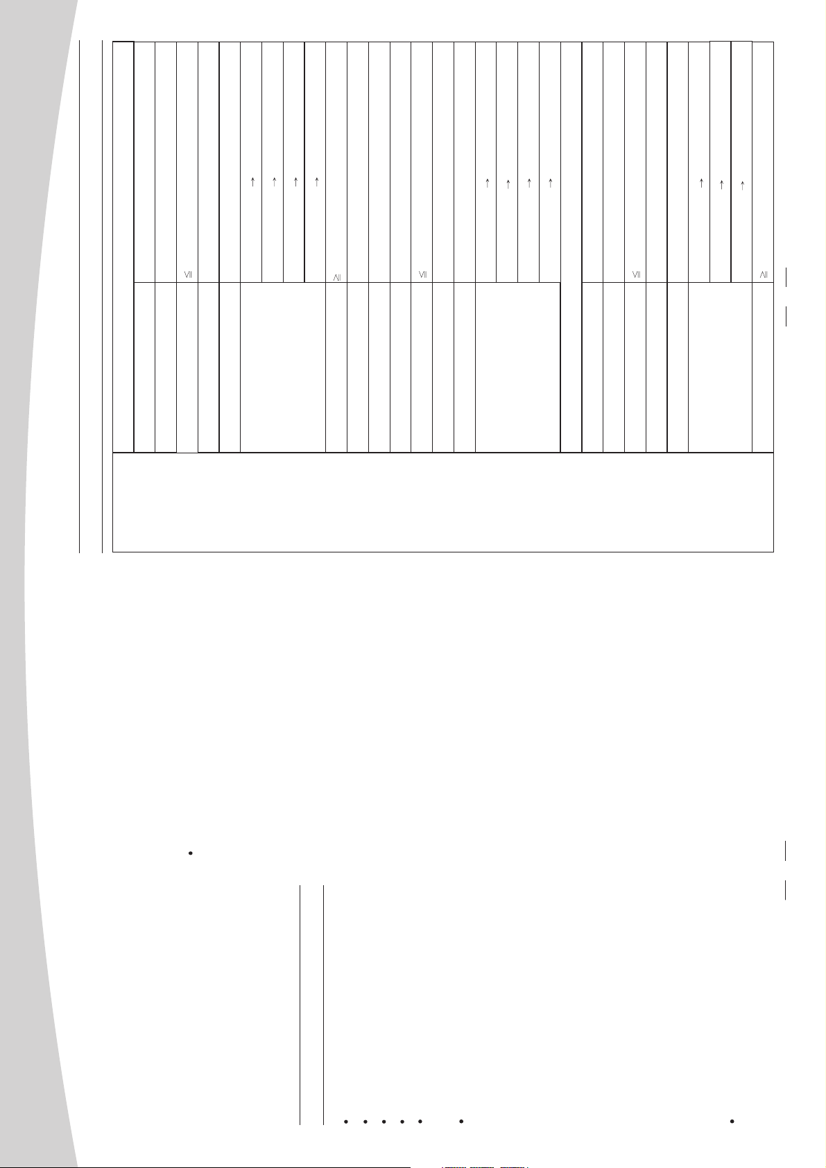
TECHNICAL SPECIFICATIONS
Electronically Balanced, Discrete Input Configuration
Microphone Input
Mono channels(CH1-CH6)
0.03% At 1kHz
20Hz to 22kHz, +/-2dBu
Frequency Response:
Distortion( THD&N)
-19dBu
-40dBu
Sensitivity
Max. Input
60dB CH MIC INPUT MONO OUT(Unbalanced)
50dB CH MIC INPUT REC OUT(Unbalanced)
60dB CH MIC INPUT MAIN OUT(XLR,balanced)
60dB CH MIC INPUT MIC OUT(Unbalanced)
Maximum Voltage Gain
103dB
SNR( Signal to Noise Rate )
+18V~+21V with switch control
Phantom power(Mic Pin2/Pin3 & Pin1)
Electronically Balanced
20Hz to 22kHz, +/-2dBu
Line Input
Frequency Response:
Input
0.03% At 1kHz
0dBu
Distortion( THD&N)
Sensitivity
Channels
20dB CH MIC INPUT MAIN OUT(XLR,balanced)
+21 dBu
Max. Input
10dB CH MIC INPUT REC OUT(Unbalanced)
Maximum Voltage Gain
20dB CH MIC INPUT MIC OUT(Unbalanced)
20dB CH MIC INPUT MONO OUT
Stereo channels(CH7/8-CH11/12)
Electronically balanced
20Hz to 22kHz, +/-2dBu
Line Input
Frequency Response:
0.03% At 1kHz
+10dBu
Distortion( THD&N)
Sensitivity
0dB CH MIC INPUT REC OUT(Unbalanced)
10dB CH MIC INPUT MAIN OUT(XLR,balanced)
+21 dBu
Max. Input
Maximum Voltage Gain
4dB CH MIC INPUT MONO OUT
103dB
15
SNR( Signal to Noise Rate )
a blower or clean with rag etc.
Don't use solvents such as benzol, alcohol,
To reduce the risk of fire or electric shock,
do not expose this apparatus to rain or
or other fluids with very strong volatility and
flammability for cleaning the apparatus body.
Clean only with dry cloth.
moisture.
Do not use this apparatus near water.
Install in accordance with the manufacture-r's
Servicing
instructions. Do not install near any heat
sources such as radiators, heat registers,
stoves, or other apparatus (including am-
Refer all servicing to qualified personnel. To
reduce the risk of electric shock, do not
plifiers) that produce heat. Do not block
any ventilation openings.
perform any servicing other than that
contained in the operating instructions unless
you are qualified to do so .
No naked flame sources, such as lighted
candles, should be placed on the apparatus.
Servicing is required when the apparatus has
been damaged in any way , such as power
supply cord or plug is damaged , liquid has
been spilled or objects have fallen into the
apparatus, the apparatus has been exposed
to rain or moisture , does not operate
IMPORTANT SAFETY INSTRUCTIONS
Read these instructions.
Keep these instructions.
Follow all instructions.
normally, or has been dropped.
The mains plug is used as the disconnect device,
Only use attachments/accessories spec-
Heed all warnings.
the disconnect device shall remain readily
operable.
ified by the manufacturer.
Power Cord and Plug
Do not defeat the safety purpose of the
polarized or grounding type plug.
A polarized plug has two blades with
one wider than the other. A grounding
type plug has two blades and a third
grounding prong. The wide blade or the
third prong are provided for your safety.
If the provided plug does not fit into your
outlet, consult an electrician for replace-
ment of the obsolete outlet.
Protect the power cord from being walk-
ed on or pinched particularly at plugs,
where they exit from the apparatus.
convenience receptacles, and the point
Cleaning
When the apparatus needs a cleaning, you
can blow off dust from the apparatus with
2
Page 6
PROFESSIONAL MIXER PREAMPLIFIER
session
preamplifier
mixer preamplifier
3
INTRODUCTION
preamplifier
mixer pre amplifier. The is a professional compact preamplifier. You will get
smooth, accurate more natural and open sound from this apparatus, and it is really ideal
for gigs, recording and fixed PA installations.
Thank you very much for expressing your confidence in our products by purchasing this
pre amplifier
This is very easy to operate but we advise you to go through each section of this
manual carefully. In this way you will get the best out of this .
mixer preamplifier
Features:
This is designed for professional application with following
features:
MONO channels:
6 COMBO inputs
MIC, MIC with Phantom power, LINE switch selector.
Low-distortion MIC pre-amp with high dynamic range, Balanced XLR and TRS input jacks.
Phantom power on each MIC input channel.
CH level control, SIGNAL LED to indicate input signal.
MIC 1 PRIORITY MUTE potentiometer
STEREO channels
CH7/8, CH9/10, CH11/12 RCA inputs
Input level control, input signal LED
STEREO LINE OUTPUT, balanced XLR for mixing LEFT/RIGHT output
MONO OUTPUT and level control
MIC OUT for monitoring CH1-CH6 output and MIC/LINE SWITCH control, LEVEL
to change output signal
STEREO REC OUT, RCA for mixing L/R OUT
3-BAND EQ for LOW, MID, HIGH
MASTER level controls the main output level, output signal LED
4-segment signal level meters, using master level to control LINE OUTPUT signal
to the AC socket;
GETTING STARTED
(1) Please check the AC voltage available in your country before connecting your
Also you should make sure that all input and output controls are turned down. This will
(2) Be sure that the main power switch is turned off before connecting to the AC socket.
preamplifier
the mixer BEFORE the power amplifier. Once you have finished your working
avoid damage to your speaker and avoid excessive noise.
(3) Before turn on the you should connect it to a power amplifier and turn on
preamplifier
preamplifier
you shall turn the mixer off AFTER the power amplifier.
(4) Before disconnecting the always turn off the power switch.
(5) Do not use solvents to clean your . A dry and clean cloth will be OK.
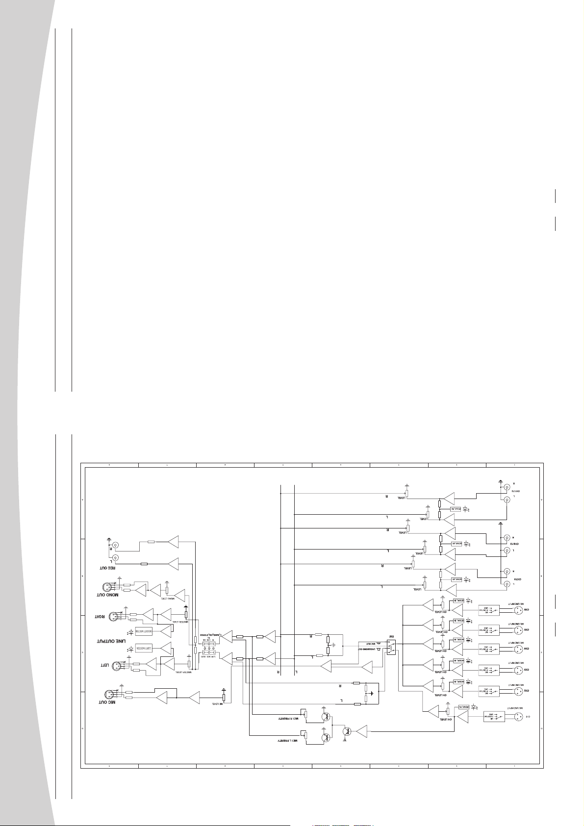
BLOCK DIAGRAM
14
Page 7
PROFESSIONAL MIXER PREAMPLIFIER
To Channel Insert
To Tape or FX Input
To Processor Input
To Channel Insert
Tip=Send Signal
Sleeve=Ground/Screen
To Processor Output
Ring=Return Signal
13
Ring=Return Signal (Connected together)
8
6
4
Tip=Signal
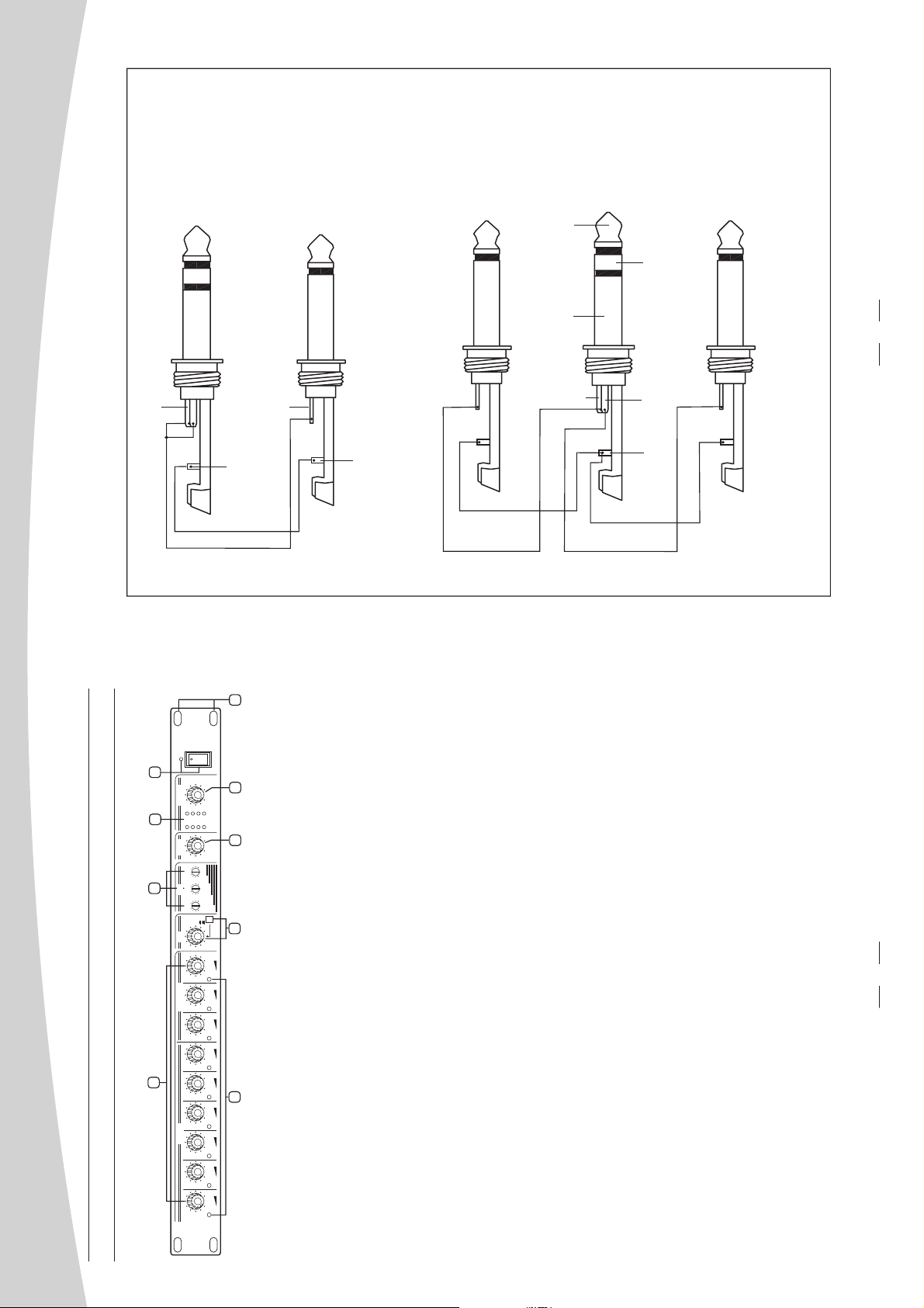
'Tapped' Connection Direct Output Lead
Tip
while maintaining the channel signal flow)
(Enables the Insert to be used as a Direct Output
Ring
Y-Stereo lead for insert Connection
(To be used when the processor does not employ a
single jack connection for the In/Out Connections)
Sleeve
Sleeve=Ground/Screen
Sleeve=Ground/Screen
9
MIXER
MIXER
SPA-12
PREAMPLIFIER
PREAMPLIFIER
ON
OFF
7
0
SIG
+10
CLIP
L R
0
HIGHMIDLOWLOW
0
0
5
OUT OUTOUTOUT
+10
+10
-10
+10
+10
-10
+10
-10
ON
OFF
volume knob is activated(at
CONTROL ELEMENTS
1
FRONT PANEL
MICINMICIN STEREOINSTEREO IN MIC EQ MONOMONO MASTERMASTER
4
LINE out has no output(this function is used for monitoring the
CH 6CH 6 CH 7/8CH 7/8 CH9/10CH 9/10 CH 11/12CH 11/12
2 3
CH 2CH 2 CH 3CH 3 CH4CH 4 CH 5CH 5
SIG SIG SIG SIG SIG SIG SIG SIG
CH 1
CH 1
0 10 0 10 0 10 0 10 0 10 0 10 0 10 0 10 0 10 0 10 0 100 10
SIG
The presence of the input signal is indicated at this LED. The strength of input signal shall determine
MIC channel 1 would have priority over other MIC input channels. This functions can be disabled by
1.MIC INPUT VOLUME KNOBS
adjusting the MIC priority knob at the back of the unit.
Adjustment of high gain may distort the original signal but too low may cause insufficient signal.
Trim each channel individually by fixing the main output to a certain level while turning off other
channels. Repeat this step and mark the level at each knob to avoid constant sound setup.
The rotary knobs for microphone inputs 1 to 6, 7/8, 9/10,11/12 are for adjustment of input signal
levels. In setup, adjust this gain to the optimum level according to the required output level.
Different channel may have different input source(ie:condenser or dynamic MIC, etc)
the brightness of the LED indicators.
2.SIGNAL LED
MIC / LINE SWITCHABLE
The button is used for selecting the MIC out or LINE out. When the
button is pressed, only CH1-CH6 have output from MIC out, MIC
3. MIC CONTROL KNOBMIC/LINE SWITCHABLE BUTTON&
present the MIC1 has no priority). The volume can be adjusted by rotating the knob to increase/
decrease the MIC output level. But
MIC out from CH1-CH6). When the button is released, all out have signal output except MIC out.
The pre amplifier is equipped with 3-band mid sweep EQ: LOW, MID & HIGH.
4. EQUALIZER
-LOW
This is the bass control. It is used to boost male voice, kick-drum or bass guitar. Your system
will sound much bigger than what it is. The gain range goes from -15dB to +15dB with a centre
frequency of 80Hz.
Page 8
19
PHPH PH PH PH PH
PROFESSIONAL MIXER PREAMPLIFIER
-MID
This is the midrange control. It provides -12dB to +12dB boost or cut with a centre frequency of
2.5kHz. It can affect most fundamental frequencies of all musical instruments and human voice.
This is the treble control. You can use it to get rid of high frequency of human voice. The gain
-HIGH
range goes from -15dB to +15dB with a centre frequency of 12kHz.
The level control knob sets the level of mono output signal, ranging from - to +10 dBu.
5.MONO
The LED meter indicate the level of input signal. Also a clipping indicator is supplied.
6.L/R LED METER
This knob is used for adjusting the LINE output level. To avoid over amplification, it's
recommended that this level be set properly.
It is advisable that the gain be set to minimum when powering the system as well as shutting
7.MASTER
down as this can eliminate sudden signal burst to your system.
8.POWER SWITCH &LED INDICATOR
This switch controls to power on/off the unit. When the unit is switched on, the LED will light up.
17
18
5
16
15
14
12
11 13
10
The unit is also provided a 24V DC backup power supply. Then the switch will control its on/off.
9.MOUNTING EAR
The mounting ear is adopted to easily install the unit on the rack.
REAR PANEL
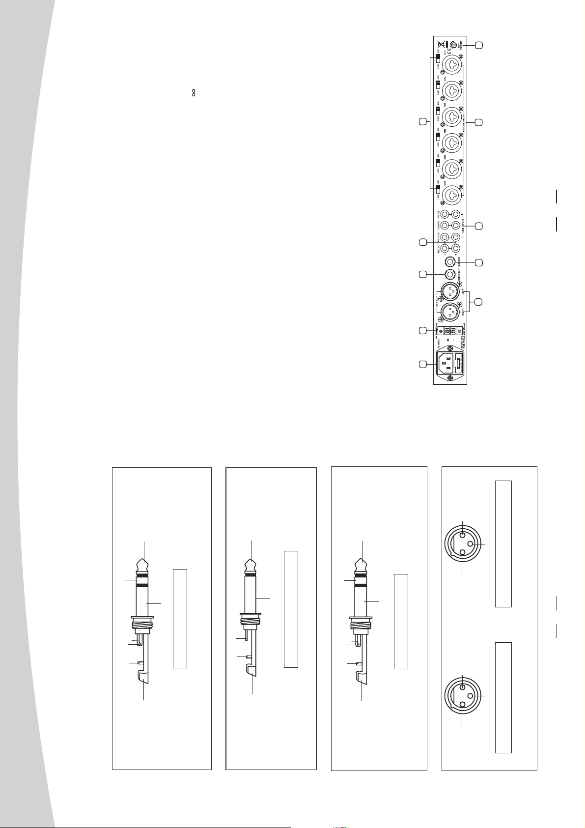
This connector is meant for the connection of the supplied power cord. Please check the Voltage
accepted by the unit and the Voltage available from AC sockets before connecting the unit to the
10.AC INLET with FUSE HOLDER
Mains.
Ring=Right Signal
Ring
Tip
Sleeve
You can connect unbalanced equipment to balanced inputs and outputs. Simply follow these schematics.
Some Final Tips on Wiring Configuration
Tip=Left Signal
Sleeve=Ground/Screen
Strain Clamp
Use for Headphone
1/4" Stereo (TRS) Jack Plug
Tip
Sleeve
Tip=Signal
Sleeve=Ground/Screen
Strain Clamp
Use forMono Line In,Mono 1/4"Jack Plugs
1/4" Mono (TS) Jack Plug
Ring=Return Signal
Tip
Ring
Sleeve
Tip=Send Signal
Sleeve=Ground/Screen
Strain Clamp
Use forInserts Points
1/4" Stereo (TRS) Jack Plug
1=Ground/Screen
1
3
2
1
2
3=Cold(-)
2=Hot(+)
1=Ground/Screen
3
3=Cold(-)
2=Hot(+)
Use forMain output
(For unbalanceduse, leave pin3 unconnected)
Use forBalanced Mic Inputs
(For unbalanceduse, connect pin1 to 3)
(seen fromsoldering side)
3-pin XLR Line Socket
(seen fromsoldering side)
3-pin XLR Male Plug
12
Page 9
PROFESSIONAL MIXER PREAMPLIFIER
11
or conference room or hall of prayer.
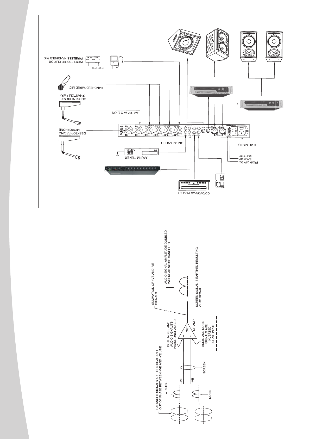
The above schematic shows a simple setup for sound reinforcement in lecture theatre
Application Example (2)......Lecture Hall/ Conference Room
Note that the priority mute is set to minimum,thus allow free mix of signal from all channels.
6
This pre-amplifier can also operate using 24V DC power supply. When both the AC and DC
source is connected, is shall operate using AC main whereas the DC supply shall be only
consumed whenever the former failed.
11.DC POWER SUPPLY
12. LINE OUT
These stereo outputs are supplied with the XLR jacks, delivering signal output from all input
sources.
13.MONO OUT
This 1/4" phone jack is unbalanced TRS connector. It can be regarded as a sum output of the
left and right of MAIN MIX.
14.MIC OUT
This 1/4" phone jack is unbalanced TRS connector used for microphone output.
15.REC OUT(PHONE JACK)
These unbalanced RCA jacks are to be connected to recording media such as cassette tape
recorder.
Double-line inputs(RCA connectors for stereo music sources). The left and right channels are
combined, resulting in a single mono signal that can be directed to one or two the audio outputs.
16.LINE INPUTS
This switch is used for selecting the LINE, MIC or phantom power(+18~21V). Push the switch
to left, the input enters into LINE mode; put the switch in the middle position, the +18V phantom
power come into force; and push the switch to right, the input becomes MIC mode.
17.LINE/MIC/PHANTOM POWER SWITCH
These balanced/unbalanced combo connector are used for the MIC/LINE signal input.
18. MIC/LINE INPUTS
The muting circuitry activates in the presence of signal from Mic 1.This potentiometer
determines the mixing level of Mic or line input signals with signals of priority channels, adjusting
it to minimum shall cut off all other inputs when signal is presence in priority channel (Mic 1).
Whereas setting it to max shall allow free mix of all signals including priority input.
Some application shall not require this feature, such as in the hall of prayer, thereby to bypass
the circuitry, adjust the level to the maximum.
19. MIC 1 PRIORITY POTENTIOMETER
Page 10
PROFESSIONAL MIXER PREAMPLIFIER
your mixer
output
effects
.
preamplifier and
7
INSTALLATION AND CONNECTION
. However, we advise you to read carefully the following section to be the real master
Ok, you have got this point and you are now in the position to successfully operate
of you own mixer. Not paying enough attention to the input signal level, to the routing of the
preamplifier
signal and the assignment of the signal will result in unwanted distortion, a corrupted signal or no
sound at all. So you should follow these procedures for every single channel:
including the preamplifier is turned off. Also, make sure all of input& controls of your
preamplifier are turned down. This will avoid damage to your speakers and avoid excessive
1. Be connecting mics or instruments, make sure that the power of all your systems components
noise.
preamplifierSet the output level of your or the connected power amplifier properly
preamplifier
Note: the power amplifier or powered monitors shall be turned on after
2. Properly connect all external devices such as mics, mixers, speakers, processor.
turned off before .
3.Now, turn on the power of any peripheral devices, then power up the mixer.
4.
5. Set HI, MID and LOW EQ controls on middle position.
SPEAKER
MONITOR
T
C
R
E
L
O
E
S
G
SELECTOR
N
I
P
AG
PAGING
L
ALL
AL
4
E
4
N
O
Z
ZONE
3
E
3
N
O
Z
ZONE
1
6
6
5
5
2
2
4
4
3
3
R
E
W
O
P
R
E
T
MAS
MASTER
1010
0
E
L
B
E
R
T
TREBLE
S
S
A
B
BASS
H
O
C
E
ECHO
0
1
10
+
+
0
1
10
-
-
0
1
10
+
+
0
1
10
-
-
0
1
10
0
L
P.
T
U
P
T
U
O
this way you will maintain good headroom and ideal dynamic range.
6. While speaking into the mic(or playing the instrument), adjust the channel Level control in
E
N
O
Z
ZONE
2
E
2
N
O
Z
ZONE
1
E
1
N
O
Z
ZONE
1
1
6
1
6
PEAK
5
5
2
2
S
U
B
S
SD/USB
D
/
R
RPT
P
T
REC
/
4
4
3
3
-VOL-
L
VO
+VOL+
L
VO
AUXAUX
3
2
T
3
U
T
2
P
U
N
P
I
INPUT
N
I
INPUT
1
T
1
U
P
N
I
INPUT
0
1
10
0
0
1
10
0
0
1
10
0
0
1
10
0
R
IE
IF
L
P
M
A
7. You can shape the tone of each channel by adjusting the equalizer controls as desired.
T
U
P
N
I
.
C
E
R
LEVEL
R
E
T
MAS
SD/MMC
X
AU
USB
MP3
g
n
i
d
r
o
c
r
Re
e
+
y
la
P
3
M
p
l
a
it
g
i
D
1
T
U
P
N
I
P.A.
O
H
C
-E
S
R
0
2
1
MPA-
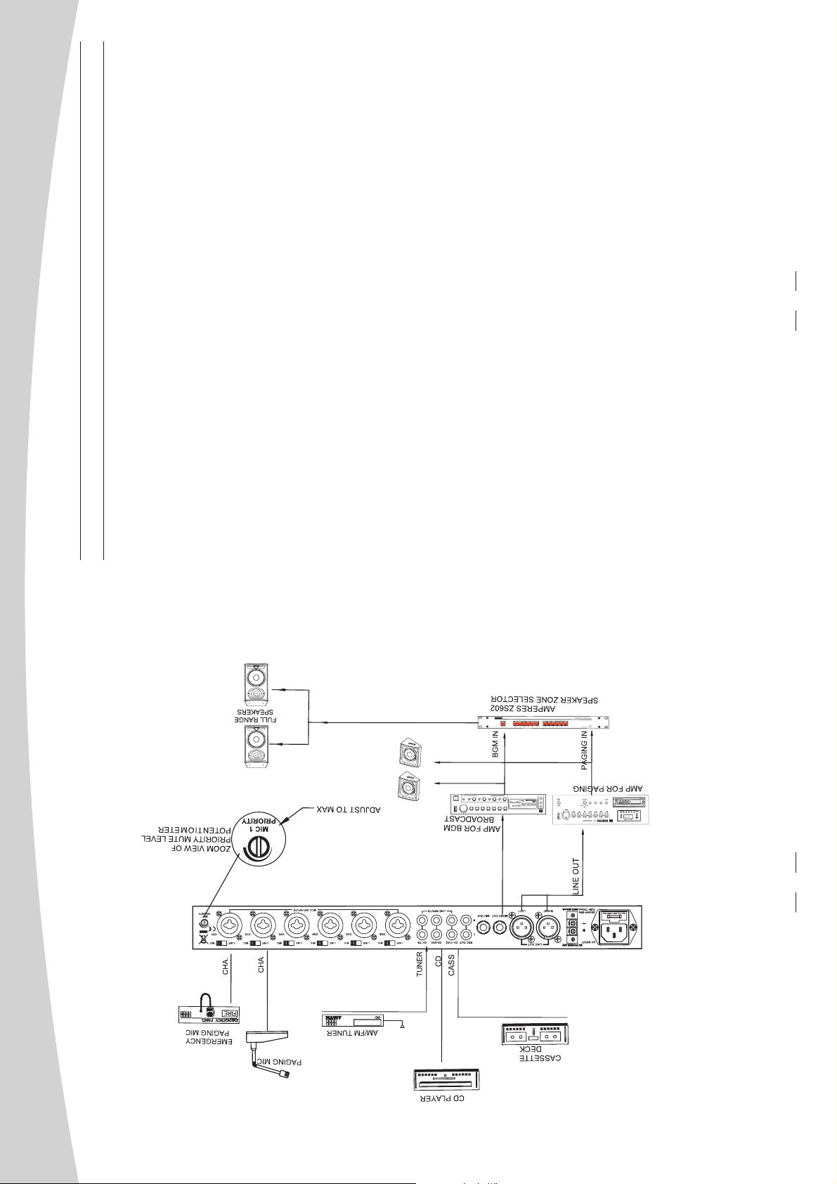
Application Example (1)......Paging System
MONO OUT
PH
PH
PH
PH
PH
PH
10
The above schematic illustrates a setup for a basic uninterrupted paging system.
Note that the priority mute level potentiometer is adjusted to the maximum to allow the
mute feature to be fully active. This level canbe adjusted mid way or so if it is to allow a paging
to be made with background music audible at lower volume.
Other equipments such as amplifier changeover, back up batteries, etc are not shown, which
may be required according to the building design requirements.
Page 11
MONITOR SPEAKER
POWER AMPLIFIER
PROFESSIONAL MIXER PREAMPLIFIER
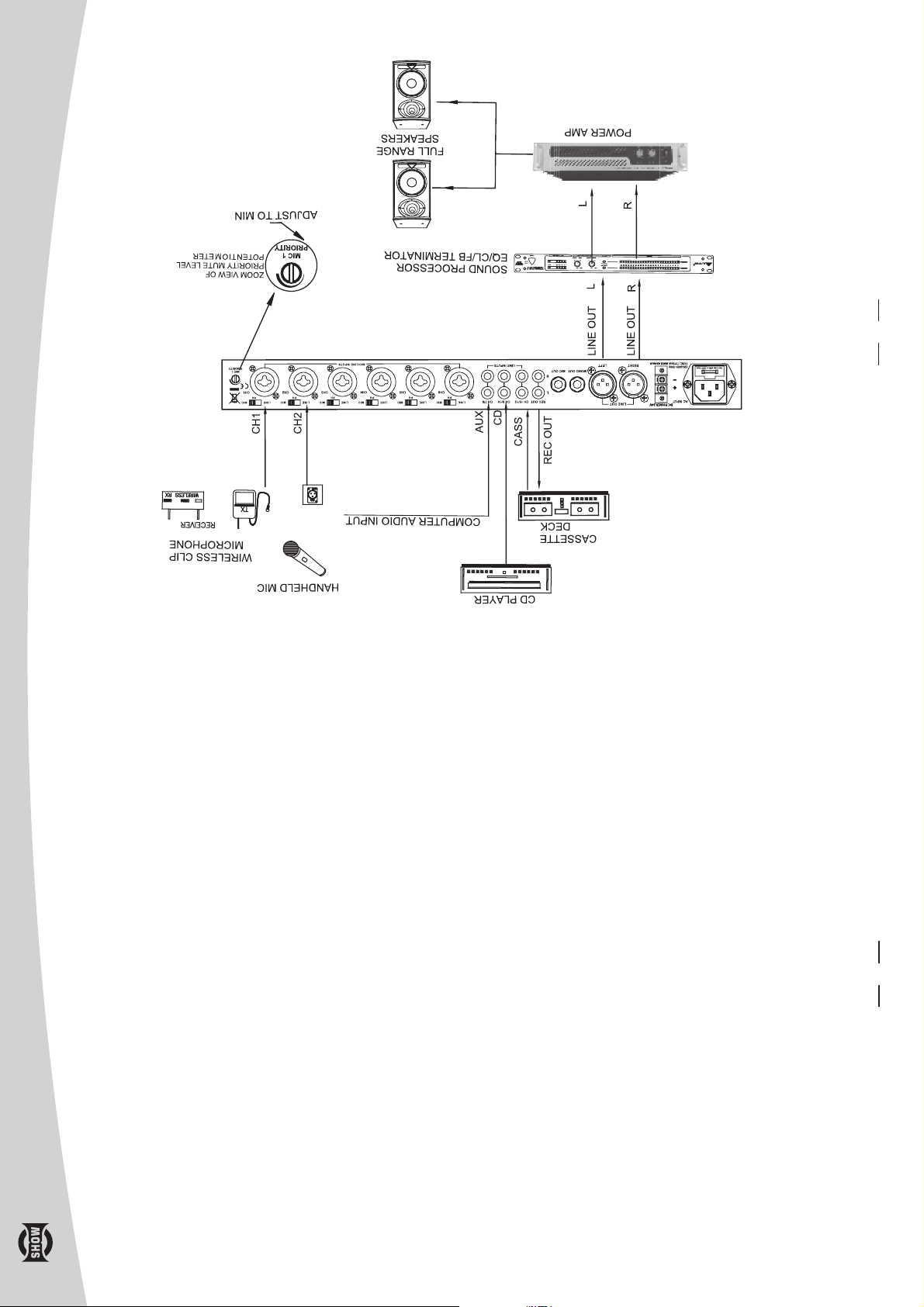
CONNECTION
POWER AMPLIFIER
9
PH
PH PH PH PH PH
RECORDER
DAT or TAPE
In unbalanced system, only one conductor carries the useful signal while the other being the
ground. Cables run in a distance may act as an antenna picking up radiations from ac sources,
Significant Difference of Unbalanced / Balanced Connections
or from dimmers as well as other noises. Since there is no out of phase signals in the cabling,
the noise signals shall superimpose with useful audio signal. As the signal level is rather small
which could not diminish the effects of radiations, they would be amplified as a lot of signal,
thereby hum, etc is heard together with audio signal, this could be disastrous if the cable is run
in a longer distance which cross with other cabling like dimmer system, etc.
Noise may appear in balanced system but at a much lower magnitude as compared to unbalanced
system. Microphones which generate amplitude in millivolts requires a better signal carrying.
Method, ie, balanced system. Signal produced are out phase with each other and when reaching
the op-amp, one conductor shall be amplifier positively while the other inverted. Noise which
do not have polarityshall be cancelledat the op-amp output. Thereby the useful signal is amplified
The understanding of how this works can be easily illustrated in the diagram below.
twice while the noise is subdued.
The Proper Cabling - Ground Looping
It is important that the mains power is connected to your equipment with earth and the power
e
syst m has a proper earthing. When hum exists, it is possibly due to poor grounding connection
of your system. There should be only one ground point in the entire system.
Pin 1 of XLR source equipment should be connected whereas at the destination, this pin is dis-
mantled. This shall eliminate grounding loop due to connections of signal ground and power
ground. A looped cable resembles an antenna picking up hum and other electromagnetic radi-
ations. Although earthed equipment may cause mains hum, disconnecting signal screen is a
8
preferred choice as it has resistance than earth ground..
 Loading...