

Page 1
14
SEIKAKU TECHNICAL GROUP
NPD-TO-201006008
PHFAA102-20101000006
105g /NH00149
A3 A4 A5
RT-DRIVE DLM-206 TOPP PRO_V1.0
RT-DRIVE DLM-206
0.10KG/1
NF03490
-RS /
TOPP PRO
LIMITED
OCT.27.2010
5PCS
Page 2
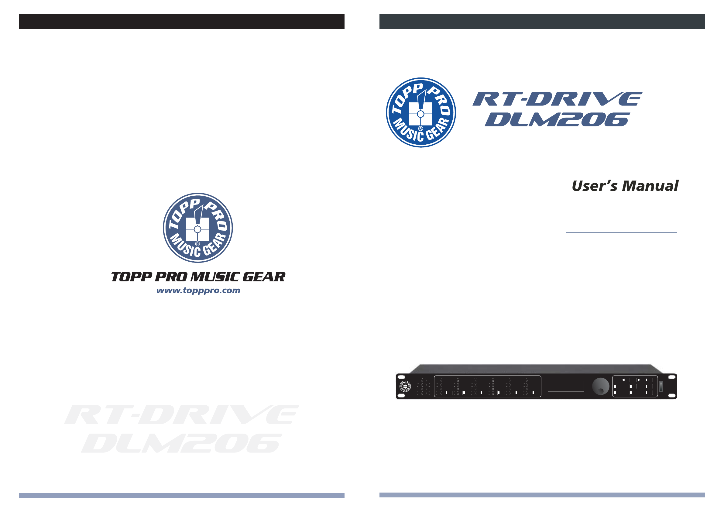
DIGITAL LOUD SPEAKER MANAGEMENT
RT-DRIVE DLM-206
A
B
OUTPUT
LEVEL
MUTE
1
OUTPUT
CLIP
LEVEL
LIMIT
3
6
12
24
30
CLIP
LIMIT
3
2 3
6
MUTE MUTE
12
24
30
CLIP
CLIP
R
CLIP
3
3
LIMIT
6
6
3
12
18
24
30
6
12
12
18
24
24
30
30
OUTPUT
LEVEL
OUTPUT
CLIP
CLIP
LEVEL
LIMIT
LIMIT
3
3
4
6
6
MUTE
12
12
24
24
30
30
OUTPUT
LEVEL
MUTE
OUTPUT
CLIP
LEVEL
LIMIT
3
6
5
6
MUTE
12
24
30
PARAMETER
CONTROL PANEL
ENTER
PASS
EXIT
LOAD
SAVE
IN
OUT
RT-DRIVE
DLM-206
UTIL
POWER
NF03490-1.0
Page 3
Page 4
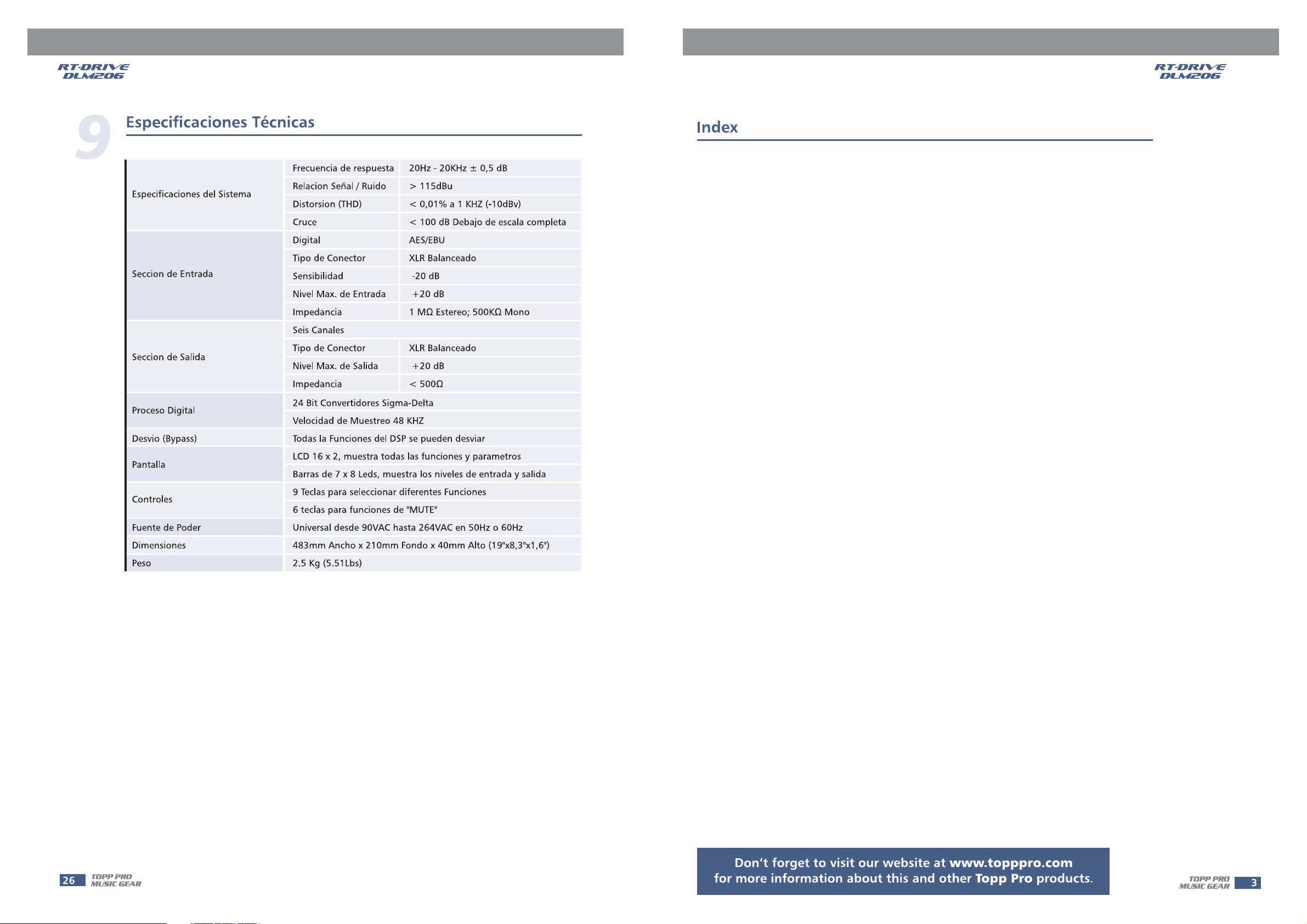
1. .......................................................................................................4
INTRODUCTION
2. .................................................................................................................4
FEATURES
3. ............................................................................................................4
USEFUL DATE
4. ... ............................................................................................5
CONTROL ELEMENTS
5. ...............................................................................7
CONFIGURATION & FUNCTIONS
6. ..........................................................................................................20
CONNECTIONS
7. ........................... .......................................................................21
REMOTE CONTROL
8. ......................................................................................................24
BLOCK DIAGRAM
9. ....................................................................................25
TECHNICAL SPECIFICATIONS
10. ...............................................................................................26
TROUBLE SHOOTING
11. ...........................................................................................................27
GUARANTEE
Page 5
Thank you for purchasing TOPP PRO product, the RT-DRIVE DLM-206. RT-DRIVE DLM-206 is 2 In Digital Signal
Processor for speaker management. For the input section, thereare Input Gain, 8 bands Parametric Equalizer
(PEQ)and delay functions for the stereo input signal processing. In the 6 / 4 output channels section,
there are equipped with Input selection, 5-band Parametric Equalizer, Crossover, Delay, Gain, Limiter,
and Mute.In order to make the users understand the ways of operation conveniently, it uses the LEDs
and LCD to indicate the respective parameter settings.
Please read this manual carefully so you can take advantages of all the features of the .
RT-DRIVE DLM-206
Thanks again for choosing TOPP PRO.
2 balanced / unbalanced Inputs and6/4balanced Outputs
10 Factory Presets and 70 User Presets
7 LEDs for every Channel Level Display
Digital Audio Input with Sample Rate Converter
Bypass button
Output Mute button for every output channel
USB user interface for PC software control
RS-485 multi-units linking interface
Input Gain Control from +12 to -40 dB
8-band Input parametric EQ with1/32Oct. Frequency step
5-band Output parametric EQ with1/32Oct. Frequency step
1364 ms Delay Line Support for Speaker Placement
Re-routable input selection for the output management
-3 dB to -48 dB Butterworth, Bessel, Link-Riley Crossover Types
Output Volume Control from +12 to -40 dB
Comp / Lim Function for every output channel
0.5 dB / step for Parametric EQ Boost and Cut
Auto-detectalbe Digital Input enable
Page 6
FRONT PANEL
PROFESSIONALHIGH POWER STEREO AMPLIFIER
SIG
SIG
SIG
SIG
CLIP
CLIP
PROT
CLIP
CLIP
PROT
ON
2
5
6
ON
OFF
OFF
CH-A CH-B
CH-A CH-B
POWER
POWER
PROFESSIONALHIGH POWER STEREO AMPLIFIER
SIG
SIG
CLIP
CLIP
PROT
CLIP
CLIP
PROT
ON
ON
OFF
OFF
CH-A CH-B
CH-A CH-B
POWER
POWER
PROFESSIONALHIGH POWER STEREO AMPLIFIER
SIG
SIG
CLIP
CLIP
PROT
CLIP
CLIP
PROT
ON
ON
OFF
OFF
CH-A CH-B
CH-A CH-B
POWER
POWER
SIG
SIG
SIG
SIG
6
ACINPUT
Useonly with a 250V fuse
90-264V 50/60Hz
RatedPower
Consumption10W
FUSE:90-120V T500mAL
210-264VT315mAL
Apparatenskall anslutas till
A102
jordatuttag nar den ansluts
tillett natverk
PUSH
NEW TIDE
21
DIGITALIN
PUSH
PUSH
USB
NEW TIDE
21
RS485IN
SERIALPORT
3
NEW TIDE
3
3
21
RS485OUT
RT-DRIVE DLM-206 DIGITAL LOUDSPEAKER
MANAGEMENT
SIGNAL
POWER
7
A
B
OUTPUT
CLIP
CLIP
CLIP
3
3
LIMIT
6
6
12
R
13
12
18
18
24
24
30
30
12
OUTPUT
CLIP
CLIP
LEVEL
LEVEL
LIMIT
LIMIT
3
3
3
6
12
24
30
2 3
1
MUTE
6
MUTE MUTE
12
24
30
6
12
24
30
1011
OUTPUT
LEVEL
OUTPUT
CLIP
CLIP
LEVEL
LIMIT
LIMIT
3
4
6
MUTE
12
24
30
OUTPUT
OUTPUT
CLIP
LEVEL
LEVEL
LIMIT
3
3
6
12
24
30
6
5
6
MUTE
MUTE
12
24
30
PARAMETER
CONTROL PANEL
ENTER
89
2 3
PASS
EXIT
IN
OUT
LOAD
SAVE
RT-DRIVE
DLM-206
UTIL
POWER
1
456
1. POWER ON / OFF
This switch is used to turn the main power ON / OFF.
2. INPUT
As the input gain control, the control range is from +12dB to -40 dB, it includes 8-band Parametric EQ
and Delay for adjustment. Due to the Gain is adjusted by digital, user c an se t the inpu t level to
suit the application. But becareful not to set the volume too high to let the signal clipped.
1
3. OUTPUT
As the output gain control, the control range is from +12 dB to -40 dB, it includes Input selection, Crossover,
5-band Parametric EQ, Delay, Gain and Compress / Limit functions. Due to the Gain is adjusted by digital,
2
1
3
user can adjust the output level to appropriate situation. The output level display was useful to the
gain setting, as it can avoid the volume too high to let the signal clipped.
4. UTILITY
Several functions parameters setting, such as ID number setting, Digital and Analog Input selection are
used for different application.
4
3
5. Edit Controls
These two buttons allow you to turn over th e p ages an d/or a variabl e numbe r o f parameters.
5
6.LOAD&SAVE
These buttons are used to load and save the u ser's pr ese ts. Up to 80 presets can be used for
parameters setting.(10 Factory Presets and 70 User's Presets)
5
7.PASS/EXIT
The button ''PASS'' is used to bypass the DSP PEQ, HP / LP, and Volume functions, also sendthe
input signal to the RT-DRIVE DLM-206 outputs directly. The but ton ''EXIT' ' is used to r etu rn to
OUTPUTS
PUSH PUSH
previous operation.
8. ENTER Control
4
56
2
3
INPUTB
1
INPUTA
This control is used to select the preset and modify the parameter's value.
AB
9. Parameter Display
All the functions' parameters setting are showing on the 2 16 characters LCD display. Us e r c an
combine Enter control and function buttons for different channels and parameters setting.
10. MUTE Button
AUDIO MIXER
All the output channels have mute button with on / off LED display for the quick silence function.
The default mute function was enabled when power on the unit.
11. OUTPUT LEVEL Meter
The entire outputs' channels have level display to indicate the signal level on the panel. The output
limiter function also display on it when it was enabled.
5
Page 7
12. Input Level Meter
These 2 LED lines are used to display the level of Input A / connectors. In order to get an up-front
distortion.
B
13. Mounting Ear
This detachable mounting ear is used for your convenient installation.
REAR PANEL
ACINPUT
Useonlywitha250Vfuse
90-264V 50/60Hz
RatedPower
Consumption10W
FUSE:90-120V T500mAL
210-264VT315mAL
Apparatenskall anslutas till
A102
jordatuttag nar den ansluts
tillett natverk
DIGITALIN
PUSH
NEW TIDE
3
21
PUSH
NEW TIDE
3
21
RS485OUT
PUSH
NEW TIDE
21
RS485IN
3
14 15 16 17 19
OUTPUTS
4
56
2
3
PUSH PUSH
INPUTB
1
INPUTA
18
14. AC Inlet and Fuse holder
This inlet is used to connect the supplied po wer cord. Please check the voltage accepted by the unit
and the voltage (90V~264V AC) from your AC sockets before connecting the unit to the Mains.
15. DIGITAL IN
AES / EBU Digital input selection, it can receive standard digital signal input bythe interface.
An d it has Sam p l e R a te Convert inside, it can receive digital inputof different sampling ratios.
16. RS485 IN / OUT
This interface is suitable for daisy-chaining s everal un i t s b y u s i ng X LR p lugs.T h e maximum quantity
is 32 units.
17. USB Port
The common PC USB Port can be used; it is the interface for PC Software to control the parameter settings.
18.INPUTA/BConnectors
These are XLR connectors, which are used to connect devices such as the channel inserts
of a mixing console.
balanced
19. OUTPUT Connectors
These are XLR connectors, which are used to connect source such as the channel inserts
of a mixing console or power amplifier's inputs.
balanced
PROFESSIONALHIGH POWER STEREO AMPLIFIER
SIG
SIG
CLIP
CLIP
PROT
CLIP
CLIP
PROT
ON
ON
OFF
OFF
CH-A CH-B
CH-A CH-B
POWER
POWER
SIG
SIG
1
2
2
1
PROFESSIONALHIGH POWER STEREO AMPLIFIER
SIG
SIG
SIG
SIG
CLIP
CLIP
PROT
CLIP
CLIP
PROT
ON
ON
OFF
OFF
CH-A CH-B
CH-A CH-B
POWER
POWER
3
5
4
3
PROFESSIONALHIGH POWER STEREO AMPLIFIER
SIG
SIG
SIG
SIG
CLIP
CLIP
PROT
CLIP
CLIP
PROT
ON
ON
OFF
OFF
CH-A CH-B
CH-A CH-B
POWER
POWER
6
4
6
5
ACINPUT
Useonlywith a 250V fuse
90-264V 50/60Hz
RatedPower
Consumption10W
FUSE:90-120V T500mAL
210-264VT315mAL
Apparatenskall anslutas till
A102
jordatuttag nar den ansluts
tillett natverk
PUSH
NEW TIDE
21
DIGITALIN
PUSH
PUSH
USB
NEW TIDE
21
RS485IN
SERIALPORT
3
NEW TIDE
3
3
21
RS485OUT
RT-DRIVE DLM-206 DIGITAL LOUDSPEAKER
OUTPUTS
4
56
2
3
PUSH PUSH
INPUTB
1
INPUTA
AB
MANAGEMENT
SIGNAL
AUDIO MIXER
POWER
6
Page 8
C
onfiguration & Functions
GETTING STARTED
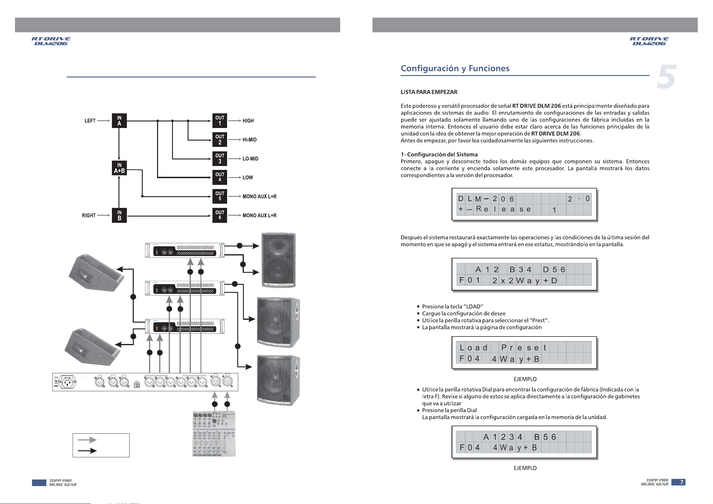
The powerful versatile signal processor is mainly designed for use with audio systems.
Its routing configurations of the input and output can be only set by recalling one of the PRESETS
included in the internal memory. So the user must be very clear about the main function of theunit in
order to get best operation of . Before you start your operation, please read the
follows carefully:
1.Configuration of the system
At first, switch off the equipment, carry out the audio and power connection from the various
components of your sound system.
Then, connect the main cord and only switch on the . The display will show the data
regarding with the operating system release for a few seconds.
Meanwhile, the system will restore the exact operating conditions at the time of switching off.
And the system will enter into default status, showing the main operating information on the display.
RT-DRIVE DLM-206
RT-DRIVE DLM-206
DL
+
-
M
R
elease
-
A12
RT-DRIVE DLM-206
2
06
B34
F
.
1
D56
.
0
2
0
5
F01
Press key
LOAD
Load the you've found.
Use the to select the .
The display will show the page:
configuration
DIAL PRESET
Load PRESET
2x2Way+D
F
Load Pr e se t
F04
Use the to find the necessary Factory PRESET (indicated by the letter ). Check
that if, among the PRESETS available, there are already some optimised for the specific
speaker enclosures being used.
Press DIAL.
The display shows the PRESET loaded in the units memory and the relative configuration:
DIAL F
4Wa y+B
(example)
A1234
B56
F04
4Wa y+ B
(example)
7
Page 9
C
onfiguration & Functions
5
2. Adjusting the input signal
It is much more important to set the input signal of a digital unit than that of
excessively high input signals will make any saturation of the A / D converters cause a typical particularly
distinct noise (high level square wave).
Proceed as follows:
Keep the outputs in status (LEDs light on).MUTERT-DRIVE DLM-206
Feed a signal in on the 's input and watch the LED meter to
obtain a good signal / noise ratio, i.e. an up-front distortion-free signal, keep the signal quite high,
but make certain the red LED doesn't light up continually.
Find out the output level setting for your mixer (or other unit) and connect it to the input of the
RT-DRIVE DLM-206.
Adjust the input gain if necessary:RT-DRIVE DLM-206
Press the key to enter into
Use the to increase clockwise or decrease counterclockwise with gain range from -40dB to +12dB.
IN INPUT GAIN
DIAL
RT-DRIVE DLM-206
CLIP
A
IN
Gain
INPUT LEVEL A-B
an analog unit, because
+01.5dB
Press DIAL.
The display will show the page (using key to convert INA orINB) in the memory:INA Gain or INB Gain IN
a
INA
G
in
0. 0dB
ain
INB
G
6
0. 0dB
Use the to change the gain value and watch the level of the signal on the LED meter until the ideal
values are reached.
3. First Setup
At this point, the first custom setup can be prepared.
The following is only the description of setup procedure.
The detailed specifications of each parameter are shown in the respective paragraphs of the manual.
Note: The regulation of the 's parameters is closely related to the characteristics of
the components of the sound system. So if you're not the expert, please refer to the documentation and technical specifications of your power amplifiers, loudspeaker enclosures, monitors, etc..
This will enable you to work faster and safely.
DIAL
Firstly, set the following parameters shown in order:
Output Pol.
Output Delay
Output Gain
Polarity of the outputs
Alignment of the speaker enclosure components
Levels of the outputs
RT-DRIVE DLM-206
8
Page 10
C
onfiguration & Functions
Disable the function on the outputs you intend using and listen the sound, carry out instrumental checks (if you have the necessary equipment) and any corrections required.
Then, if necessary, adjust the values of the following functions:
Output EQ
Output Limiter
Note: In this first phase of setting up your sound system, the adjustment of these functions (which if
not Indispensable during installation) can wait. But do remember that adjusting the equalizers can
also affect the single Level. If considerable equalization changes are made, remember to check &
adjust the output levels too.
Explanations of letters
The letters indicate the inputs:
A=Input A
B=Input B
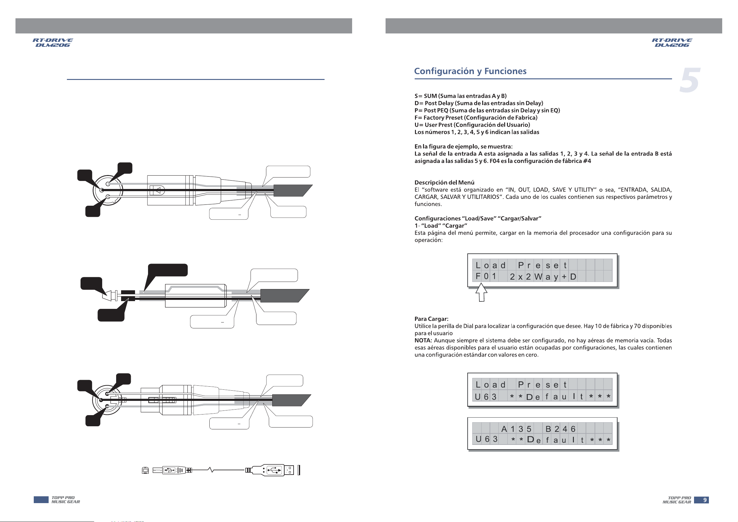
S=SUM(sum of inputs A and B)
D=post Delay(Sum 1)
P=post PEQ (Sum 2)
Numbers 1, 2, 3, 4, 5 and 6indicate the respective outputs.
In the example:
The signal connected to Input A is assigned to outputs 1, 2, 3 and 4.
The signal connected to Input B is assigned to outputs 5 and 6.
MUTE
Output equalizers
Output limiters
F04
A1234
4Wa y+ B
B56
5
4. THE MENU MAP CONFIGURATION DESCRIPTION
The control software is organized in and menus, each of which contains
the relative types of parameters and functions.
Load & Save PRESET
1) Load PRESET
This menu page allows the required PRESET to be loaded and made operatively.
IN, OUT, LOAD, SAVE UTILITY
Load Pr e se t
F01
F
To load a PRESET:
Use the to reach the required PRESET.
10 Factory PRESETS, 70 User PRESETS are available.
Note:
unused by custom are automatically occupied by the , which contains a standard
start configuration with all the values of the various parameters at zero.
DIAL
since the system must always be configured, there are no empty memory areas. All the User areas
PRESETS *Default* PRESET
2x2Way+D
9
Page 11
5
C
onfiguration & Functions
Load Pr e se t
U63
**
D
fault
e
***
A135 B246
U63
2) Store & Naming PRESET
Use key to create new PRESETS, i.e. to save all the current system settings.SAVE
Store
U
0
To save a PRESET:
Use to reach the memory area in which the PRESET is to be saved.DIAL
Note: Factory PRESET Factory
In this procedure, the areas aren't available, since the
PRESETS PRESET,
Nevertheless save it in a area, modify it as required and then store it again in the same
Press The page appears, by means of which it s possible to edit the name of the
PRESET to be saved. The name of the start PRESET (i.e. of the PRESET currently loaded) is proposed as
default. The cursor takes up position on the first of the twelve character spaces available.
can not be permanently remember that it is possible to load a Factory modified.
User PRESET User.
DIAL. PRESET Naming
**
D
fault
e
Preset
2
Default
***
*
***
10
Pr es2et
]
At this point:
If you decide to accept and confirm the name suggested, press
If you want to abort procedure (for example because you've chosen the wrong memory
area) and return to procedure, press
If you want to assign a new name to the you're storing:
- use the and keys to position the cursor on the required character
- use to enter the alphanumeric value wanted
DIAL
- after finishing, press
Naming
Store PRESET EXIT.
ENTER.
2W+2
Nami ng
MAX
PRESET
]
ENTER.
Page 12

C
onfiguration & Functions
5. Function Keys
IN key
IN
Input Gain
Input EQ
Input Delay
1) Input Gain
Press key to go into Input Gain page. Use to control input gain. Rotate the clockwise to
IN DIAL DIAL
increase and counterclockwise to decrease.
ain
INA
G
+
01.5d
B
5
Allows to adjust the amplification of the signal fed in through Inputs A and B.
Editing values are in the range 2dB ~ -40dB, with 0.5dB steps.+1
ain
CLIP
G
E
Q1
-
INPUT LEVEL A-B
Low
.
5dB20
Px
B
INB
Note:
Setting the input signal of a digital unit is particularly important, much more than on an analog
unit, as any saturation of the A / D converter due to an excessively high input signal causes a typical
particularly distinct noise. To achieve a good signal / noise ratio, i.e. an up-front distortion free signal,
feed a signal in on the 's input and watch the LED meter. Keep the
signal quite high, but make certain the red LED doesn't light on continually.
2) Input EQ
8-band Input parametric EQ with 1 / 32 Oct. Frequency step allows to alter the overall tone of the
signal connected to the respective input.
This component's characteristic quality and programmability enable it to be used so effectively
and flexibly as to make the use of graphic equalizers often unnecessary.
Press key and use , to adjustIN DIAL PREV & NEXT Input EQ
RT-DRIVE DLM-206
INA
30. 5
3. 20
+00 .5
11
Page 13
C
onfiguration & Functions
5
Each equalizer has 5 pages (one for each filter), showing the name of the input it affects & the number
of the filter.The following editable parameters are available for each filter:
(A) Type of filter
Allows to choose among Peaking, Low or High Shelving with a slope of 6 or 12 dB per octave.
(B) Centre Frequency / Cutoff Frequency
Allows to choose the centre frequency of the Peaking curve, or the cutoff frequency of Shelving curves.
Peaking
INA
2k
2k
Peaking
Low Shelving
Q1
E
00
00
Low Shelving
kaeP
High Shelving
B
Px
-5.01.0
-5.01.0
High Shelving
(C) Bandwidth
Allows to choose the width in octaves of the Peaking.
INA
30.5
(D) Gain
Allows to control the boost or cut of the selected frequencies.
Peaking
Q1
E
INA
30.5
Low
3.20
E
Px
B
+00.5
Q1
Low
3.20
Low Shelving High Shelving
+00.5
B
Peaking
Px
12
Page 14
C
onfiguration & Functions
3) Input Delay
Press key and keys to adjust the delay lines of Input delay ranges
IN PREV & NEXT Input A, Input B.
from 0 to 1364mS with 0.021 step.
INA
OUT key
Del ay
OUT
0000.021
mS
OP MIX
OP EQ
OP HPF
OP LPF
OP Delay
5
OP Gain
OP Polarity
OP CompLim
1) OP MIX
Press key to access output mix page, use & and to adjust values.OUT ENTER, PREV NEXT DIAL
O
P1
INBV
2) OP EQ
Output equalizer with 5 parametric filters.
Also called Channel EQ, allows to alter the tone of each individual output.
The characteristics of quality & programmability are identical to those of the Input Equalizer &
enable this unit to be used extremely effectively and flexibly.
Each equalizer has 5 pages (one per filter), indicating the name of the output effects and
the number of the filter.
MIX
SUM1x
Ax
IN
SUM2V
13
Page 15
5
C
onfiguration & Functions
O
P1
E
Q1 Px
1k00
Example: Output1-Filter 1
Since technical specifications and editing fields of the are identical to those of the ,
please refer to section for descriptions.
3) OP HPF & LPF
Each Xover has 2 slightly different pages (one for each filter), where the name of the output
it affects and the type of filter are shown.
O
Low Pass Filter
The low-pass filter allows all the frequencies below a specific frequency to pass, whereas it cuts all the
frequencies above it.
High Pass Filter
The high-pass filter allows all the frequencies above a specific frequency to pass, whereas it cuts all the
frequencies below it.
INPUT Eq
P1
1k00Hz
LPF
Output 1- low pass filter
BUT 12
Peak
2.00
Output EQ Input EQ
O
P1
1k00Hz
B
-00.5
HPF
Output 1- high pass filter
BUT 12
LPF HPF
Signal segment obtained with the combination of LPF and HPF.
4) Output Delay
Only delays the signal of a specific output.
Internal alignment of a speaker enclosure components.
Use , and keys to adjust the delay lines of outputs 1, 2, 3, 4, 5, and 6.OUT key DIAL , PREV NEXT
O
P1
Delay
0000.063
LPF
mS
HPF
14
Page 16

C
onfiguration & Functions
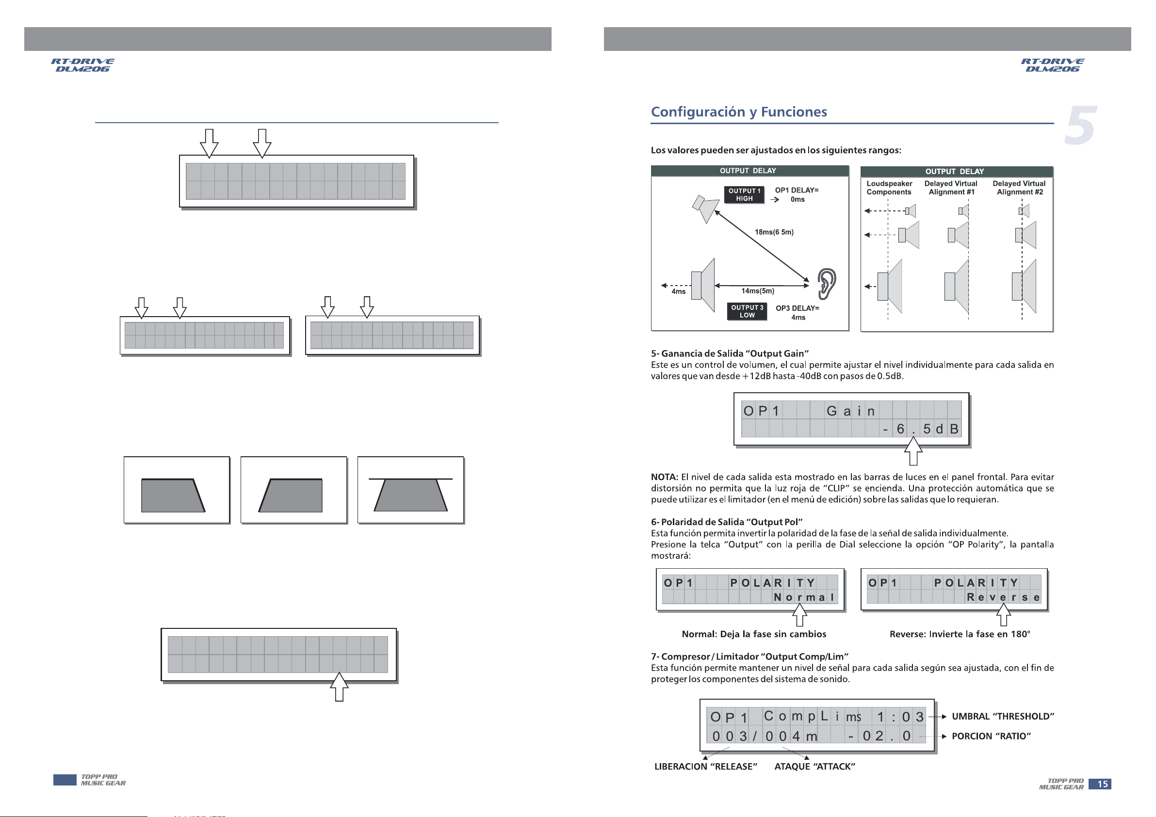
The values can be set in the following ranges:
OUTPUT DELAY
OUTPUT 1
HIGH
4ms
5) Output Gain
Output level control. Allows to adjust the signal level of each individual output.Editing valuesare between
+12dB ~ - 40dB, with 0.5dB steps.
14ms(5m)
OUTPUT 3
LOW
OP
OP1 DELAY=
18ms(6 5m)
OP3 DELAY=
1
0ms
4ms
Gain
Loudspeaker
Components
-6.5
OUTPUT DELAY
OUTPUT DELAY
Delayed Virtual
Alignment #1
d
B
Delayed Virtual
Alignment #2
5
Note: OUTPUT LEVEL LED
The level of each output is shown by the respective meter. To avoid distortion,
don't Let the red lights up. As automatic protection, you can also enable the (EDIT
menu) on the outputs that require it. In this case, remember that enabling the LIMITER changes the
display mode on the relative LED meter: in fact, the level shown is no longer the absolute output level,
but the level of the signal in relation to the threshold.
6) Output Pol
Controls the output's polarity. Allows to invert the phase of the signal of individual outputs.
Press key, use to adjust output polarity as shown in followingOUT DIAL
Normal: leaves the phase unchanged
OP
1
7) Output CompLim
Allows to keep the signal of each individual output within a set level, which can be used effectively to protect the components of a sound system.
CLIP LED LIMITER
LIMITER
Reverse: shifts the phase through 180 , inverting it.
POLA
O
P1
RITY
Norm
a
CompL
OP
1
I
i
m
1:03
POLA
R
RITY
ever
s
e
003/ 004m
- 02. 0
S
15
Page 17

C
onfiguration & Functions
5
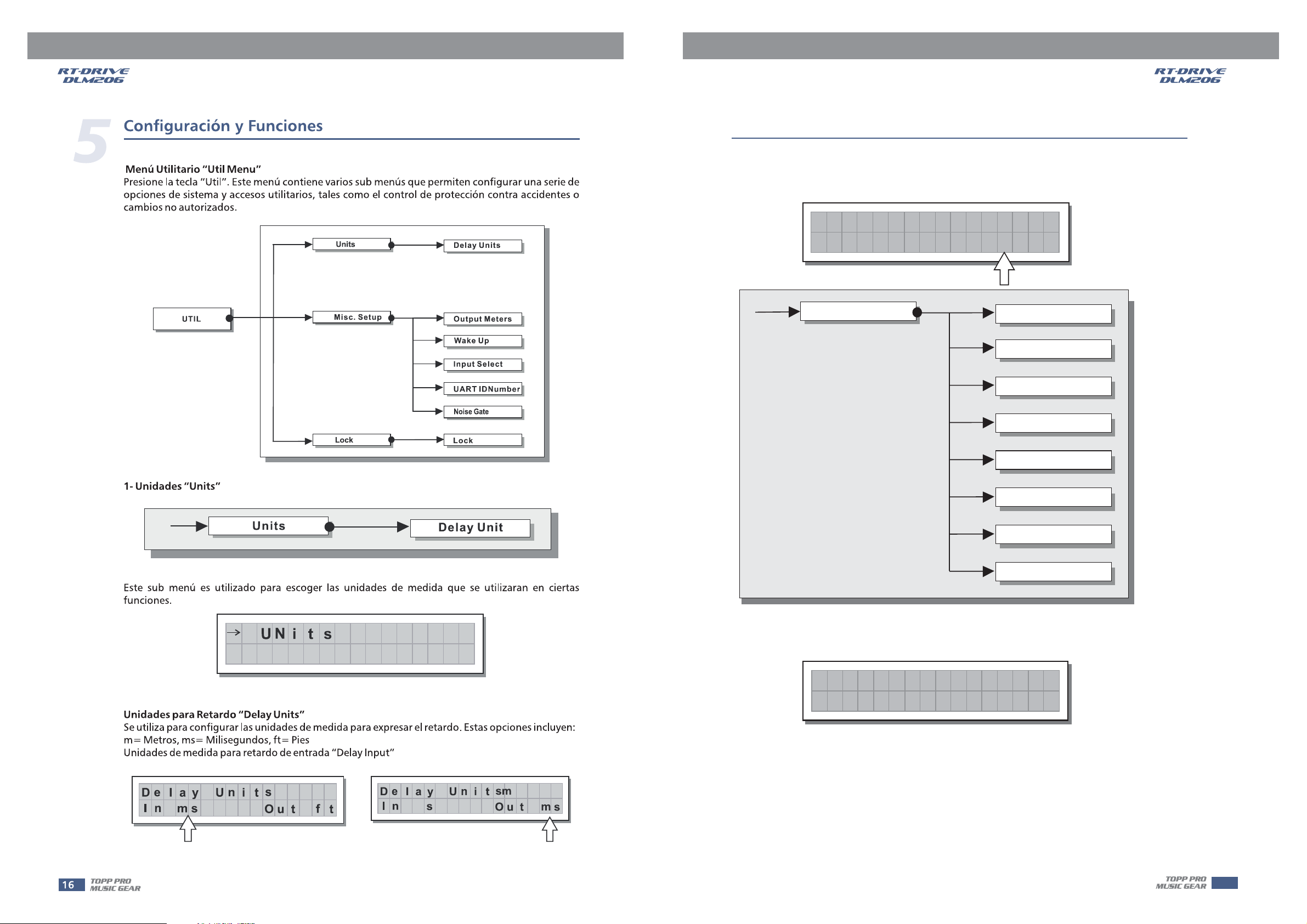
UTIL menu
This menu comprises a series of submenus that allow to set a series of system options and
access certain utilities, such as the control of protection against accidental or unauthorized changes:
UTIL
Units
Misc. Setup
Lock
Delay Units
Output Meters
Wake Up
Input Select
UART IDNumber
Noise Gate
Lock
1) Units
Units
Used this submenu to choose the measurement units to be used with certain functions.
N
its
U
Delay Units
Used to set the measurement units in which Delays are expressed (DELAY menu).The options include:
meter milliseconds - = feet
m= - ms = ft
Measurement units for Input Delay
Delay Unit
n
I
ms
s
f
t
tOu
Delay Unit
n
I
Delay Unit
m
s
s
m
t
sOu
16
Page 18

C
onfiguration & Functions
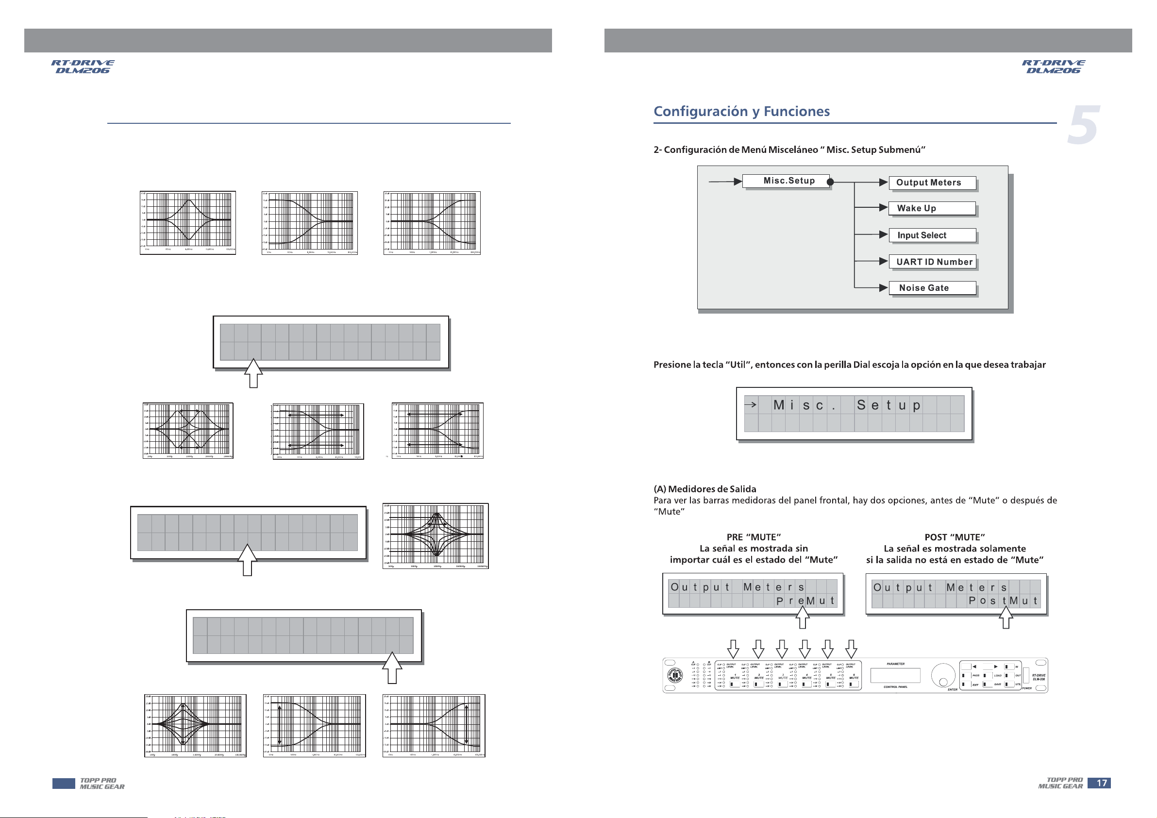
2) Misc. Setup submenu
Misc.Setup
Output Meters
Wake Up
Input Select
UART ID Number
Noise Gate
Use key to set a series of system options.ENTER
Mi sc . Se t up
(A) Output Meters
Used to decide whether to display the outputs signal before or after MUTE. The options include:
5
PreMute
the signal is always shown
no matter what the MUTE status
utput Meters
re
P
A
B
CLIP
3
3
6
6
12
R
12
18
18
24
24
30
30
CLIP
CLIP
LEVEL
LIMIT
LIMIT
3
3
1
6
6
MUTE
12
12
24
24
30
30
OUTPUT
CLIP
OUTPUT
CLIP
LEVEL
LIMIT
3
2 3
6
MUTE MUTE
12
24
30
OUTPUT
LEVEL
CLIP
LIMIT
12
24
30
the signal is only shown when
the output isn't in MUTE
utput Meters
O
tOu
M
OUTPUT
LEVEL
3
4
6
MUTE
CLIP
CLIP
LIMIT
3
6
12
24
30
LEVEL
LEVEL
LIMIT
3
6
5
6
MUTE
MUTE
12
24
30
OUTPUT
OUTPUT
PARAMETER
CONTROL PANEL
PostMute
PASS
EXIT
ENTER
o
stM t
IN
OUT
LOAD
SAVE
UTIL
uP
POWER
RT-DRIVE
DLM-206
(B) Wake Up
Allows to choose the mode in which functions are restored when the is
switched on.
The options include:
Normal
when switched on, the system restores the last
MUTE configuration before switching off
MUTE RT-DRIVE DLM-206
Mute
when switched on, the system automatically
sets all the outputs in MUTE
Wa k e U p
Nor mal
Wa k e U p
Mu t e
17
Page 19

C
onfiguration & Functions
5
(C) Input Select
Used to choose inputs. The options include:
PUSH
NEW TIDE
21
RS485IN
3
Analog Inputs
Digital Inputs
Input Select
A102
Useonly with a 250V fuse
D
ACINPUT
90-264V 50/60Hz
RatedPower
Consumption10W
FUSE:90-120V T500mAL
210-264VT315mAL
Apparatenskall anslutas till
jordatuttag nar den ansluts
tillett natverk
igi ta
PUSH
NEW TIDE
3
21
DIGITALIN
l
The inputs selected become and .
Input Sel ect
PUSH
NEW TIDE
3
21
RS485OUT
Input A Input B
Any signal on the inputs not selected is ignored.
(D) UART ID Number
Range from 01 to 31
UART
ID
(E) Noise Gate
Controls the noise gate on / off.
Noise
Gate
ON
Ana l o
g
OUTPUTS
4
56
3
Number
Noise
Auto Inputs
Input Sel ect
2
INPUTB
1
01
Gate
A
PUSH PUSH
INPUTA
OFF
u
o
t
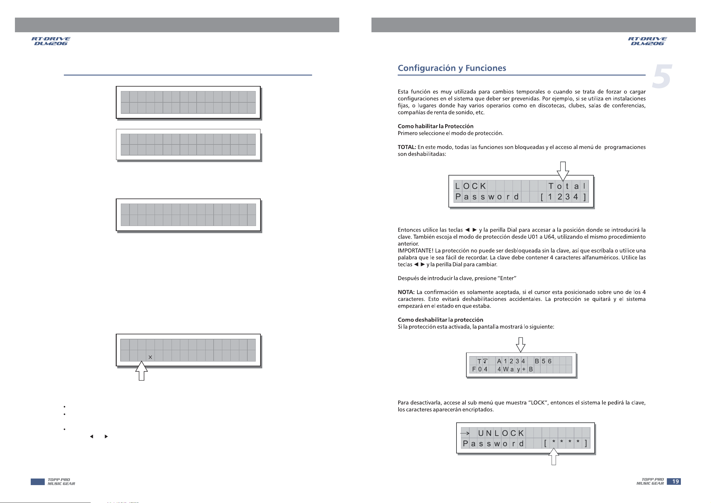
3) LOCK SUBMENU
Used to enable or disable the protection of the system against accidental or unauthorized changes.
Lock Lock
This function is very useful whenever even temporary changes or tampering with the settings
stored in the system must be prevented. For example: fixed installations used by several operators
(discotheques, clubs, conference halls, etc.), sound system rental, etc.
How to enable protection
First of all, choose the protection mode:
Total:
all editing functions are blocked and access to the PRESET menu is disabled
LOCK To t a
Pas sword
Then use the and keys and to access the area in which the is entered.
Also choose protection modes from U01-U64 with same operation procedures as Total.
IMPORTANT! password!
The protection cannot be unlocked without the So write it down or at least
choose a word that is easily remembered. The password is made up of four alphanumerical characters,
obtainable using the and keys & editable with the
After entering the password, press
DIAL password
DIAL.
ENTER.
[1234]
l
18
Page 20

C
onfiguration & Functions
Confirmation is only accepted if the cursor is positioned on one of the passwords four characters.
Note:
This allows to avoid accidental enabling, without having seen the password. Protection is enabled
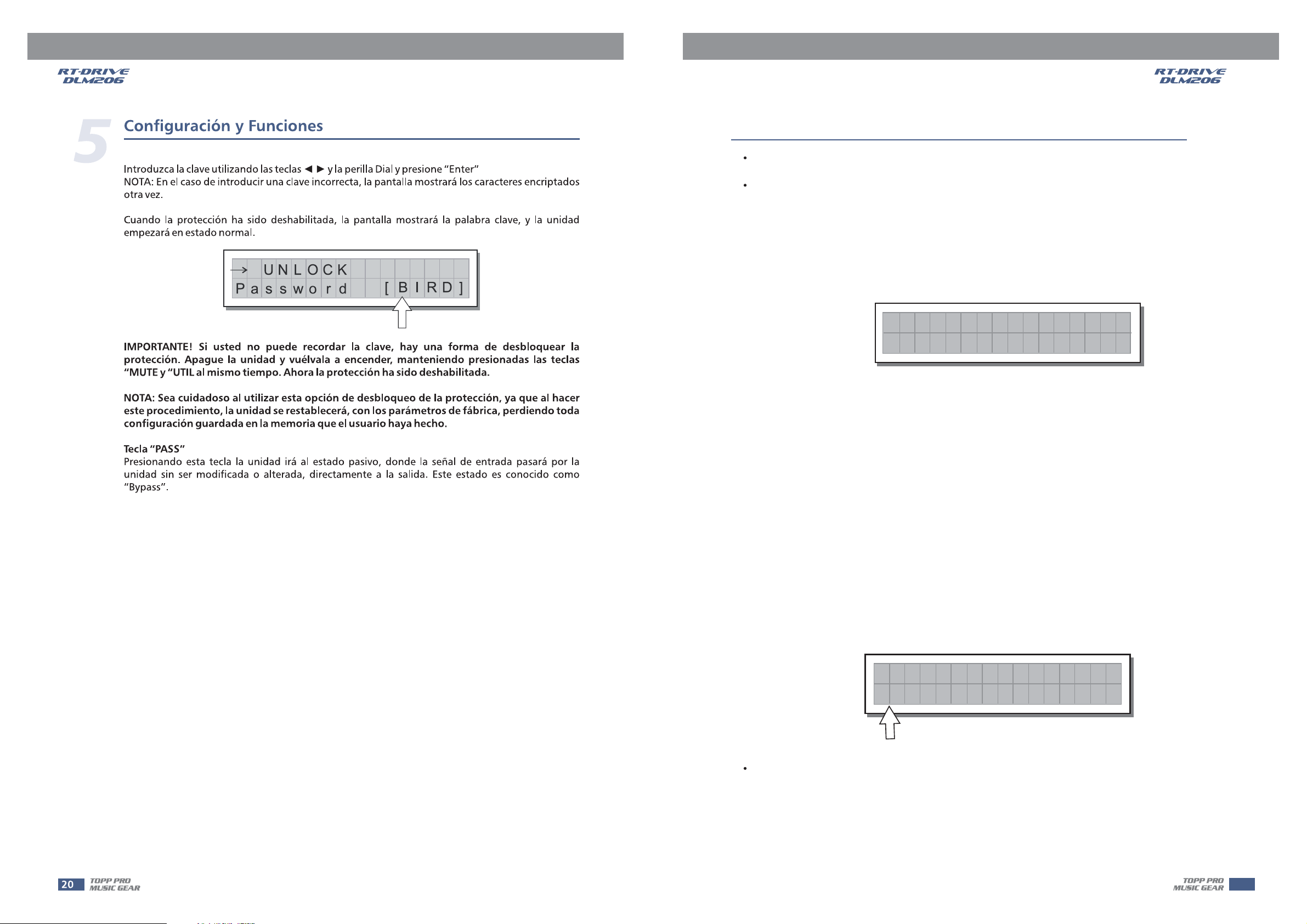
and the system takes up default status.How to disable the
protection
5
If the protection is enabled, when the system is in default status (i.e. when none menu are lit
and therefore no type of editing is enabled), the following appears on the display:
T
F04
To unlock the protection:
Access the Submenu.
The display shows the prompt for entering the password to unlock the protection.The four alphanumeric
characters of the password are encrypted.
LOCK
A1234
4Wa y+ B
Total Protection enabled
B56
LEDs
UNLOCK
Pas swo r d
Enter in the using the combination of the keys and the then press
Note:
password and DIAL, ENTER.
in the event of an incorrect password, the display prompts again, encrypting all the characters
again.
[****]
UNLOCK
[B
I
Pas swo r d
Protection is unlocked and the system enters default status.
Important!
press " " & " " keys at same time. Now, the protection is unlocked..
Note: by means of this way to unlock the system, the user's memory will be eliminated, thatis, all the user
PASS key
Press key to go into system bypass status.PAS S
If you can't remember the password, there is an easy way to unlock the protection. Turnthe unit on,
MUTE1 UTIL
presets will be lost. Please use carefully!
RD]
19
Page 21
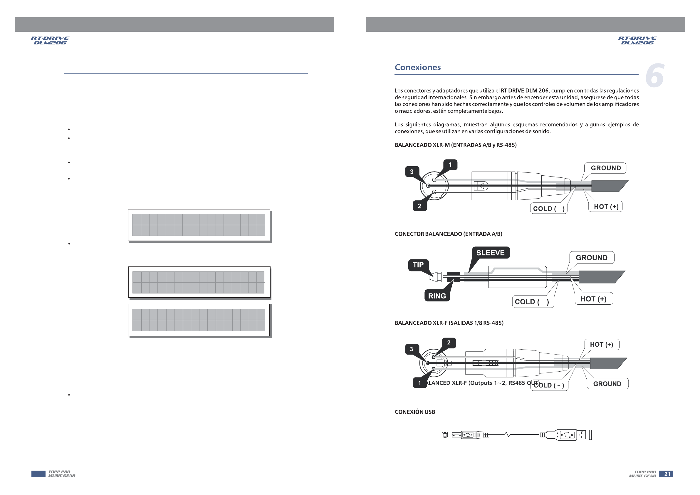
CONNECTIONS
6
The adapter that meets all the international safety regulations is supplied with your
Before power on the , please make sure all connections have been made correctly
and the volume controls of the amplifier or mixer are turned down completely.
The following diagrams show the schemes of the recommended cables and some connection examples
various system configurations.referred to
BALANCED XLR-M (InputsA&B,RS-485 IN)
3
2
BALANCED JACK (InputsA&B)
RT-DRIVE DLM-206
1
COLD ( )
RT-DRIVE DLM-206
GROUND
HOT (+)
.
SLEEVE
TIP
RING
BALANCED XLR-F (Outputs 1~2, RS485 OUT)
2
3
1
COLD ( )
COLD ( )
GROUND
HOT (+)
HOT (+)
GROUND
20
USB Connection
Page 22

REMOTE CONTROL
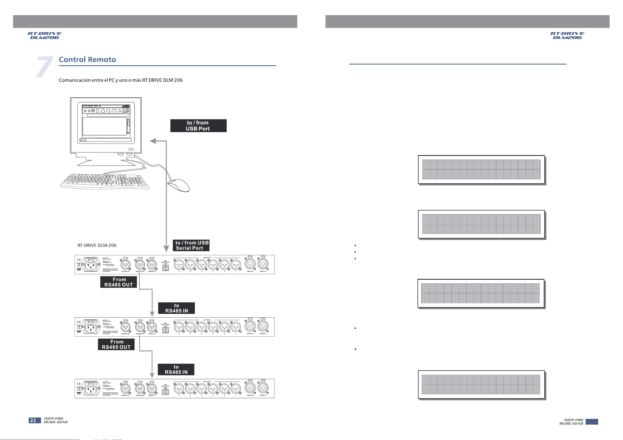
Communications: PC & one or more connectionRT-DRIVE DLM-206
7
to / from
USB Port
RT-DRIVE DLM-206
ACINPUT
Useonly with a 250V fuse
90-264V 50/60Hz
RatedPower
Consumption10W
FUSE:90-120V T500mAL
210-264VT315mAL
Apparatenskall anslutas till
A102
jordatuttag nar den ansluts
tillett natverk
RS485 OUT
ACINPUT
Useonly with a 250V fuse
90-264V 50/60Hz
RatedPower
Consumption10W
FUSE:90-120V T500mAL
210-264VT315mAL
Apparatenskall anslutas till
A102
jordatuttag nar den ansluts
tillett natverk
From
RS485 OUT
ACINPUT
Useonly with a 250V fuse
90-264V 50/60Hz
RatedPower
Consumption10W
FUSE:90-120V T500mAL
210-264VT315mAL
Apparatenskall anslutas till
A102
jordatuttag nar den ansluts
tillett natverk
DIGITALIN
From
DIGITALIN
DIGITALIN
PUSH
NEW TIDE
3
21
PUSH
NEW TIDE
3
21
PUSH
NEW TIDE
3
21
PUSH
NEW TIDE
3
21
RS485OUT
PUSH
NEW TIDE
3
21
RS485OUT
PUSH
NEW TIDE
3
21
RS485OUT
PUSH
NEW TIDE
21
RS485IN
PUSH
NEW TIDE
21
RS485IN
PUSH
NEW TIDE
21
RS485IN
3
3
3
to/fromUSB
Serial Port
USB
SERIALPORT
to
RS485 IN
USB
SERIALPORT
to
RS485 IN
USB
SERIALPORT
OUTPUTS
4
56
OUTPUTS
4
56
OUTPUTS
4
56
2
3
2
3
2
3
PUSH PUSH
INPUTB
PUSH PUSH
INPUTB
PUSH PUSH
INPUTB
INPUTA
INPUTA
INPUTA
1
1
1
21
Page 23
REMOTE CONTROL
7
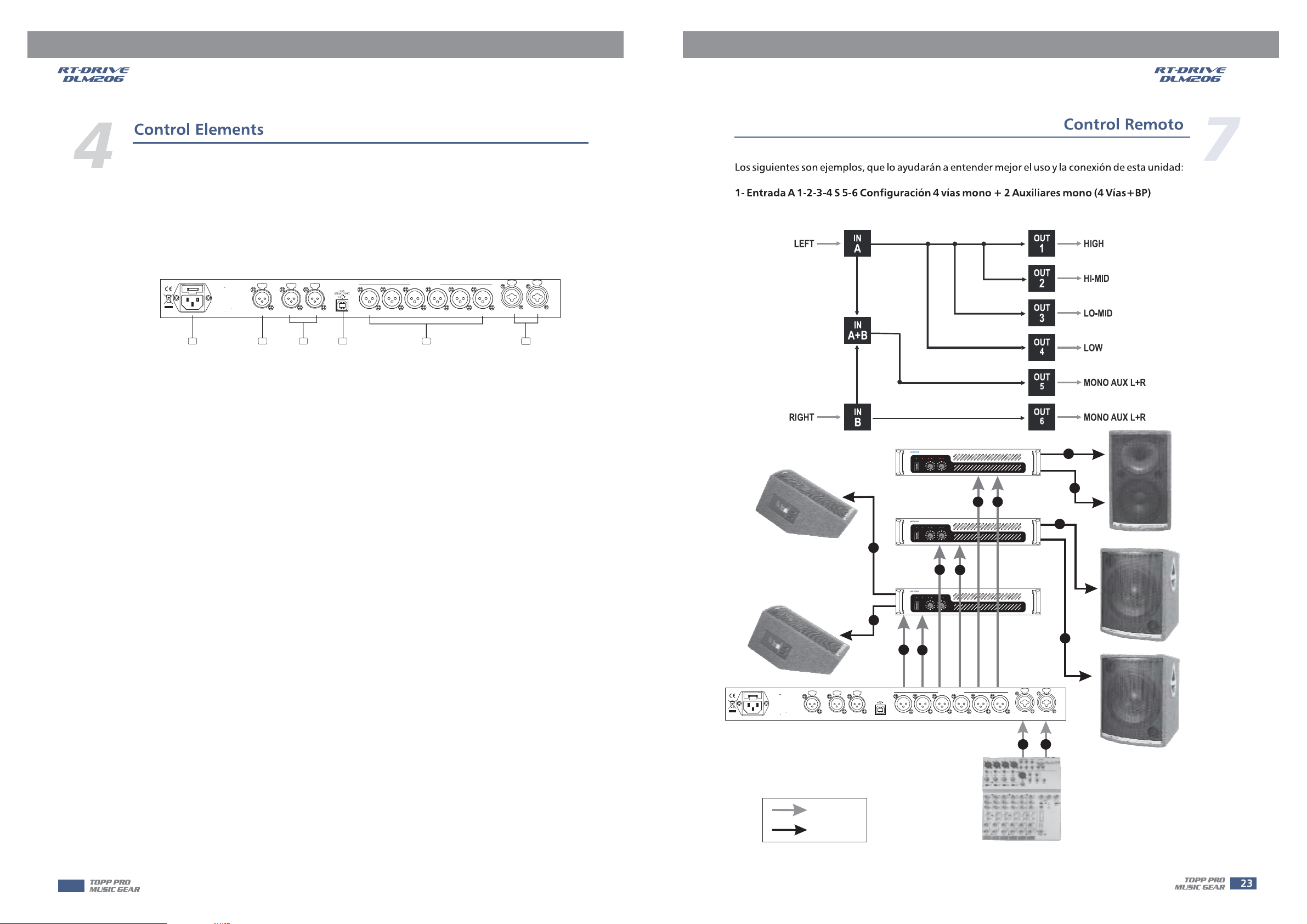
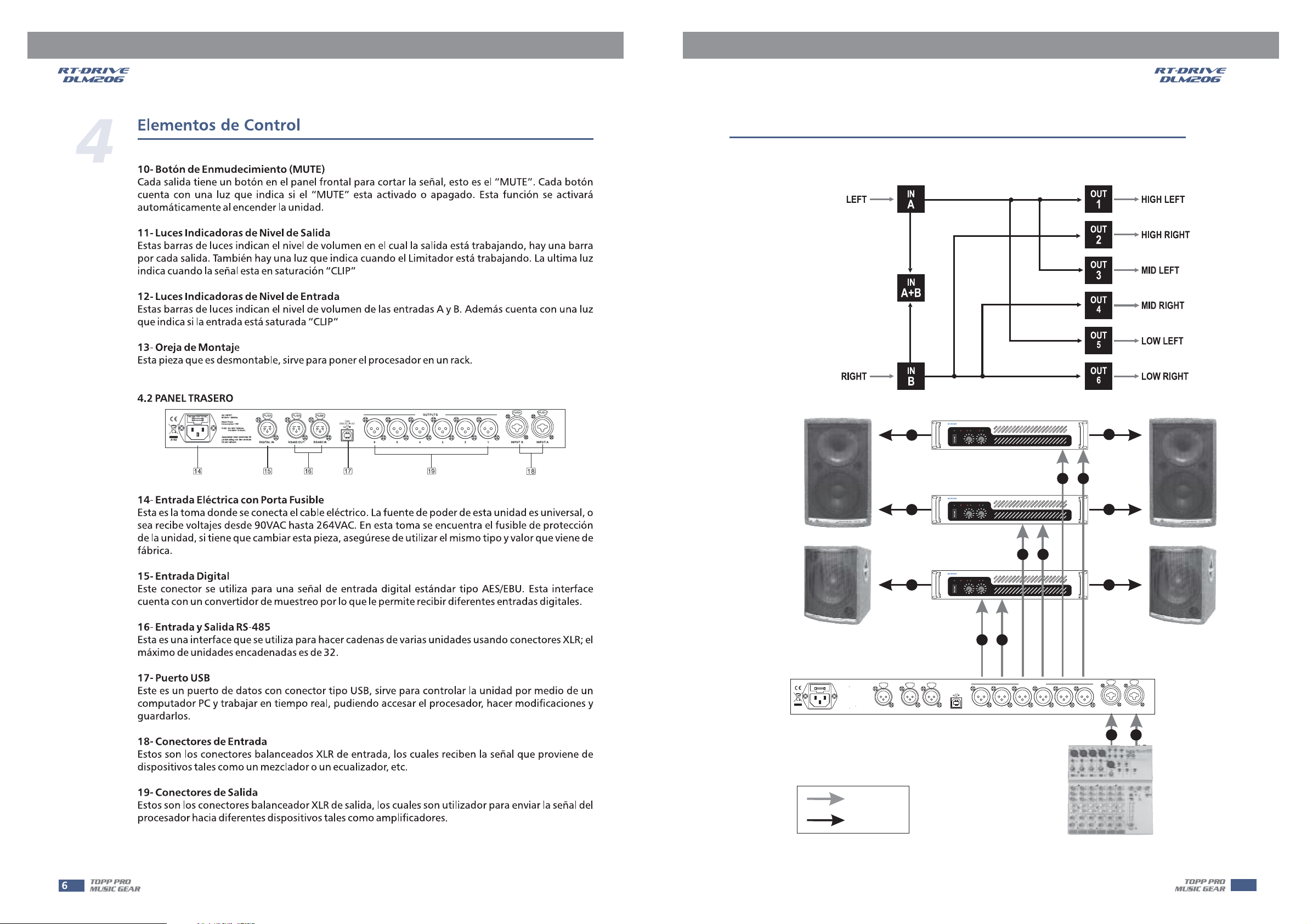
The following examples will help you better use and connect the unit.
1.A1324 S56 4-WAY4 MONO+2MONOAUX[4WAY+BP]
PROFESSIONALHIGH POWER STEREO AMPLIFIER
SIG
SIG
CLIP
CLIP
PROT
CLIP
CLIP
PROT
ON
ON
OFF
OFF
CH-A CH-B
CH-A CH-B
POWER
POWER
SIG
SIG
1
POWER
POWER
5
POWER
POWER
6
6
ACINPUT
Useonlywith a 250V fuse
90-264V 50/60Hz
RatedPower
Consumption10W
FUSE:90-120V T500mAL
210-264VT315mAL
Apparatenskall anslutas till
A102
jordatuttag nar den ansluts
tillett natverk
PUSH
NEW TIDE
21
DIGITALIN
PUSH
PUSH
USB
NEW TIDE
21
RS485IN
SERIALPORT
3
NEW TIDE
3
3
21
RS485OUT
RT-DRIVE DLM-206 DIGITAL LOUDSPEAKER
MANAGEMENT
PROFESSIONALHIGH POWER STEREO AMPLIFIER
SIG
SIG
SIG
SIG
CLIP
CLIP
PROT
CLIP
CLIP
PROT
ON
ON
OFF
OFF
CH-A CH-B
CH-A CH-B
4
PROFESSIONALHIGH POWER STEREO AMPLIFIER
SIG
SIG
SIG
SIG
CLIP
CLIP
PROT
CLIP
CLIP
PROT
ON
ON
OFF
OFF
CH-A CH-B
CH-A CH-B
5
OUTPUTS
4
56
2
2
1
3
3
4
PUSH PUSH
2
3
INPUTB
1
INPUTA
AB
22
SIGNAL
POWER
AUDIO MIXER
Page 24
REMOTE CONTROL
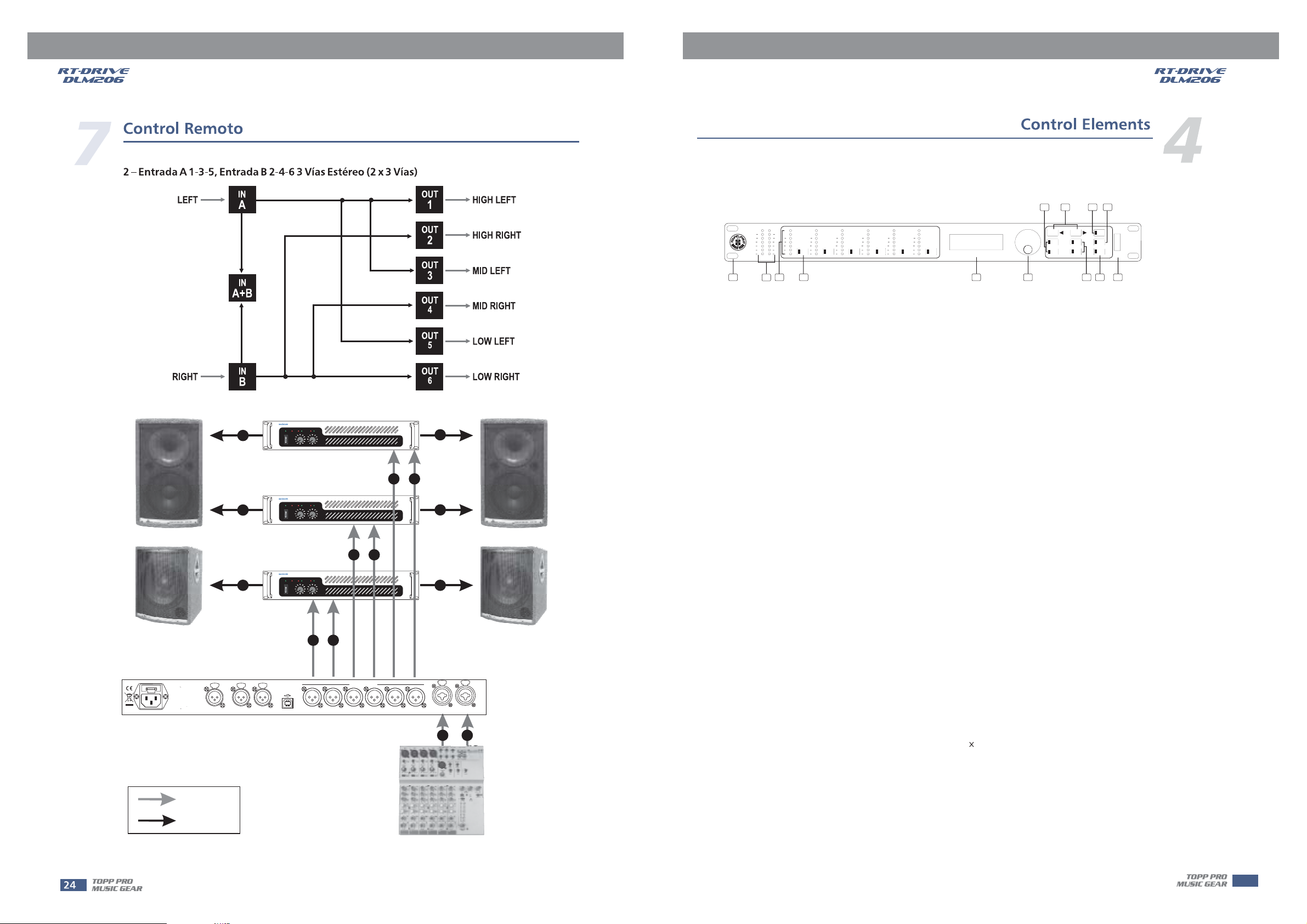
2. A135 B246 3-WAY STEREO [2X3WAY]
2
PROFESSIONALHIGH POWER STEREO AMPLIFIER
SIG
SIG
CLIP
CLIP
PROT
CLIP
CLIP
PROT
ON
ON
OFF
OFF
CH-A CH-B
CH-A CH-B
POWER
POWER
7
SIG
SIG
1
PROFESSIONALHIGH POWER STEREO AMPLIFIER
SIG
SIG
SIG
SIG
CLIP
CLIP
PROT
CLIP
CLIP
PROT
ON
5
6
ON
OFF
OFF
CH-A CH-B
CH-A CH-B
POWER
POWER
PROFESSIONALHIGH POWER STEREO AMPLIFIER
SIG
SIG
CLIP
CLIP
PROT
CLIP
CLIP
PROT
ON
ON
OFF
OFF
CH-A CH-B
CH-A CH-B
POWER
POWER
SIG
SIG
6
ACINPUT
Useonly with a 250V fuse
90-264V 50/60Hz
RatedPower
Consumption10W
FUSE:90-120V T500mAL
210-264VT315mAL
Apparatenskall anslutas till
A102
jordatuttag nar den ansluts
tillett natverk
PUSH
NEW TIDE
21
DIGITALIN
PUSH
PUSH
USB
NEW TIDE
21
RS485IN
SERIALPORT
3
NEW TIDE
3
3
21
RS485OUT
RT-DRIVE DLM-206 DIGITAL LOUDSPEAKER
MANAGEMENT
SIGNAL
2
1
3
4
3
5
5
OUTPUTS
4
56
2
3
PUSH PUSH
INPUTB
1
INPUTA
AB
AUDIO MIXER
POWER
23
Page 25

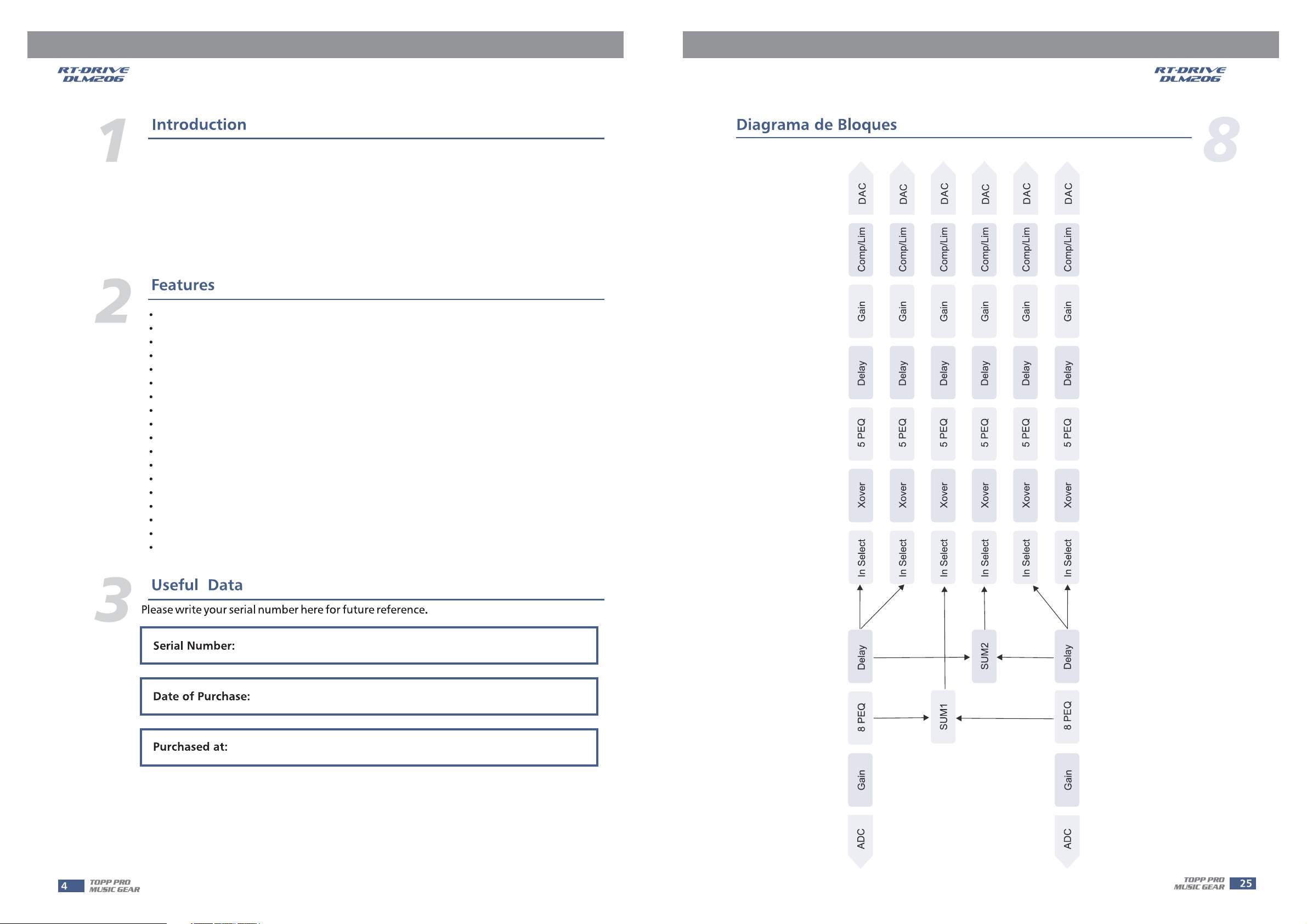
8
BLOCK DIAGRAM
DAC
Comp/Lim
Gain
Delay
5 PEQ
Xover
DAC
Comp/Lim
Gain
Delay
5 PEQ
Xover
DAC
Comp/Lim
Gain
Delay
5 PEQ
Xover
DAC
Comp/Lim
Gain
Delay
5 PEQ
Xover
DAC
Comp/Lim
Gain
Delay
5 PEQ
Xover
DAC
Comp/Lim
Gain
Delay
5 PEQ
Xover
24
In Select
Delay
8 PEQ
Gain
ADC
In Select
In Select
SUM1
In Select
SUM2
In Select
In Select
Delay
8 PEQ
Gain
ADC
Page 26

System Specification
Input Section
Output Section
Digital Processing
Bypass
Display
TECHNICAL SPECIFICATIONS
Frequency Response 20 Hz~20 kHz, +/-0.5 dB
S/N Ratio
Distortion (THD)
Cross-talk
Digital
Typ e
Sensitivity
Max. Input level
Impedance
Six Channels
Typ e
Max. Output level (bypass)
Impedance
24-bit sigma-delta converters
48 kHz Sampling Rates
Bypass all the DSP function
16 2 LCD Display for parameters setting and function select
7 8 LED for Input and Output Level Display
>115 dBu
<0.01% at 1 kHz (-10 dBv)
<100 dB below full scale
AES/EBU
Balanced XLR
-20 dBu
+20 dBu
1 M /Stereo; 500 k /Mono
Balanced XLR
+20 dBu
<500
9
Control
Power Supply
Dimension (W D H)
Weight
9 buttons for different DSP functions selection
4/6 buttons for Outputs channels Muting
AC90-264V, 50/60Hz
483 210 40 mm (19" 8.3" 1.6")
RT-DRIVE DLM-206: 2.5 Kg (5.51 lb)
25
Page 27

TROUBLE SHOOTING
Symptom
No sound
No sound, speaker is
connected to working
AC power but won't
come on
No sound
Speaker comes on
No sound with
microphone connected
to MIC / LINE input
Signal sounds distorted
and very loud,LIMIT light
is lit most of the time
Lots of hiss in sound,
mixer controls are
at very low settings.
HumorBuzz
Likely Cause
Speaker not connected to
active AC power
Power not switched on
Speaker power cable is faulty
or improperly connected.
Blown fuse
Signal source (mixer, Amp
instrument) is not sending
Faulty cables & connections
Microphone requires
phantom power
Excessive input signal, trying
to exceed the capabilities of
the speakers
Improper gain structure
Improper A/Cgounding,
ground loops
Excessively long unbalanced
cable run
Improper system gain
structure
What to do
Verify that speaker is connected and that the circuit is on
Switch on power and verify that power Led is on
*Re-seat the power cable at both ends;
*Substitute a known-good power cable
*Check fuse & replace with same type "spare fuse in holder"
*Check if the signal LED indicators are lit on
*Verify that the tape or CD is playing;
*Use headphones to verify that the instrument is actually sending
an audio signal
*Disconnect and re-seat signal cables;
*Replace suspected cable with a known-good cable
The EON does not supply phantom power. Switch to a dynamic
microphone, use a battery powered microphone (if possible),
use and external phantom power supply for condenser type
microphones.
*Reduce the output level of the source;
*Turn down the level controls on the speaker;
*Use additional EON speakers
*Make sure that the MIC / LINE switch is in the LINE(disengaged)
position;
*Reduce the level settings at speaker, Review the Owner's Manual
for your mixer and adjust controls as needed;
*Input sensitivity(gain);
*Channel faders;
*Master faders;
*"lift" audio ground by using XLR/F to XLR/M adapter on one end
*Re-route audio cables away from AC power and lighting cables.
*Use the balanced outputs(if available)of your mixer or source
equipment to drive your EON speakers.
*Use"DI"(direct injection) box to convert unbalanced equipment
output to a balanced output.
Reduce the INPUT level controls and increase the output level
of your source devices.
26
Page 28
27
Page 29
 Loading...