

Page 1
RT-DRIVE
DLM808
DIGITAL PROCESSOR
AUDIO MATRIX PROCESSOR
Page 2

2
Page 3
1. Introduction
4
2. Features
3. Usefull Data
4. Function Buttons and LED Indicators
5. Rear Panel
6. DSP Control
1. Configuration of IP Address
2. Configuration of Device Connection on Initial Page
3. Input DSP Channel
4. MATRIX
5. Output DSP Channel
6. Save/Load/Copy
7. System
7. Web Configuration of LAN Module
8. Technical information
9. Guarantee
10.Notes
4
4
5
7
9
9
10
11
14
15
16
17
18
19
20
21
3
Page 4
1
Introduction
Thank you for choosing TOPP PRO. The new TOPP PRO MUSIC GEAR RT-DRIVE DLM808 is an
audio matrix processor, with 8 input and 8 output channels, with high-definition LCD to display
current status at real time, with network port to expand network devices. It is available for
large-scale place, such as theater, broadcast hall, gymnasium and conference center and so on.
Every TOPP PRO audio product is strictly tested and complied to very strict standards.
Please carefully read this manual before starting operation! Thank you again for choosing TOPP
PRO MUSIC GEAR RT-DRIVE DLM808.
Features
2
3
All input channels are equip with GATE/EXP/CROSSOVER/PEQ/DELAY/COMPRESSOR function
All input channels are equip with Gain/Crossover/PHASE/PEQ/DELAY/COMPRESSOR function
8*8 audio matrix
With 8 channels in and 8 channels out audio interface expansion card (DANTE)
Match with PC and App operation software, which is convenient for user
User can on-line update DSP and MCU Firmware via internet
4
Page 5
Function Buttons and LED Indicators
3
1
5
2
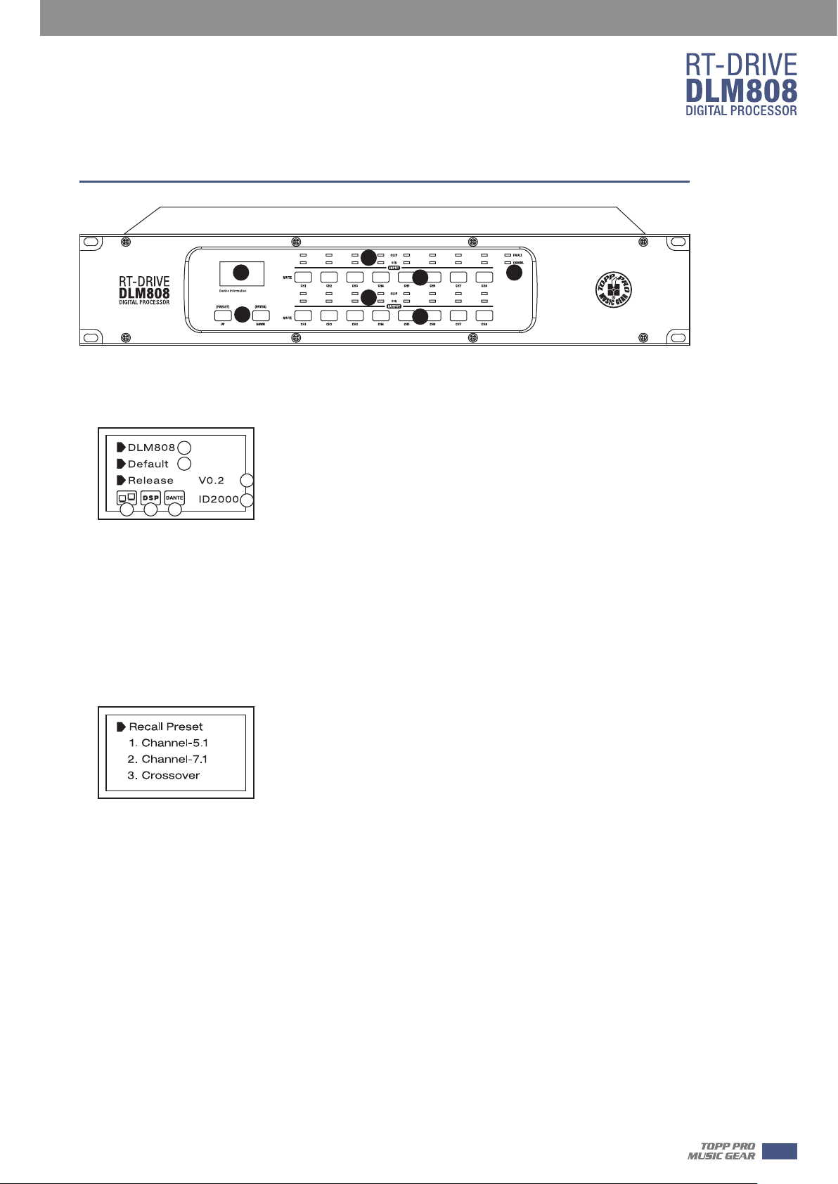
1. LCD Screen
Display device information, such as device name, port number, preset etc.
1) Initial page
1
2
3
5 6 7
(1) Device name
(2) Current preset
(3) Current release version
(4) Current ID, when connecting with device, the ID can be obtained automatically.
(5) This image means the PC isn’t connecting with DLM808; if connecting well, the two devices
inside box will flash alternately.
(6) This image means DSP communicate well, if fault, it will show DSP!.
(7) This image appears when Dante option inserted in DLM808, or it will disappear.
4
4
6
7
4
2) Preset list
2. UP and DOWN buttons (PRESET and ENTER)
The two buttons can meet operation demands of LCD screen.
-UP: Click to list up.
-DOWN: Click to list down.
-PRESET: Its function is as following:
1) Enter Preset List
Hold to press this button for about 3 seconds to enter “Recall Preset” page, you can see
totally 32 presets, every preset can be set at PC, after finishing set, then save the preset, it
can be synchronously saved to DLM808.
2) Exit from Current Page
In“Recall Preset”page,hold to press PRESET button again for 3-4s, exit from current page
to initial page.
3) Indicate System Information
In initial page, hold to press PRESET button for 3-4s, you can see system information
showed on LCD screen. Such as system version(System V1.0), firmware version(Firmware
V1.0).
5
Page 6
4
Function Buttons and LED Indicators
- ENTER. Its function is as following:
1) Load Preset
Click UP/DOWN button to select preset, then Hold to press the “ENTER” button for about 3
seconds to recall the selected preset. After recalling successfully, the screen will display “Load
OK”.
2) Exit from Preset List Page
When the selected preset is empty, hold to press ENTER for 3s, no preset to load, the system
will exit from current page and return back to initial page.
3) Reset to defaults
Hold to press both PRESET and ENTER buttons for 8s to erase all memory settings, and reset to
defaults.
Note that whichever page it is, if hang it without any operation, the system will go back to initial
page about 5 seconds later.
3. Input Signal LED indicating
Indicate input connection status. When you connect this device to other host, the LEDs indicate
corresponding Mic port connection status at back panel.
LEDs indicate as below:
-CLIP(RED). It means current MIC input signal overload.
-SIG(GREEN). It means some signal input from current MIC port.
4. Input Channel MUTE Button
Press CH1-8 buttons, the corresponding background LED light, which means to mute signal from
selected channels.
5. Output Signal Indicating LED
Indicate output connection status. When you connect this device to other hosts, LEDs here
indicate corresponding XLR port connection status at back panel.
LEDs indicate as below:
-CLIP(RED). It means current XLR output signal overload.
-SIG(GREEN). It means some signal output from current XLR port.
6. Output Channel Select Button
Press CH1-8 buttons, the corresponding background LED light, which means signal can output
from selected channels.
7. Status LED Indication
LED indicating as below:
-COMM.(GREEN). Power on DLM808 and connect it with PC by router or CL-4, then open
DLM808’s software control page on PC, it lights if communication is common; while it turns off
if communication is fault.
-FAULT(RED). It lights when DSP runs fault, you can see fault information on LCD screen, see
details in section 1 about LCD Screen. At this time please check your device configuration.
6
Page 7
Rear Panel
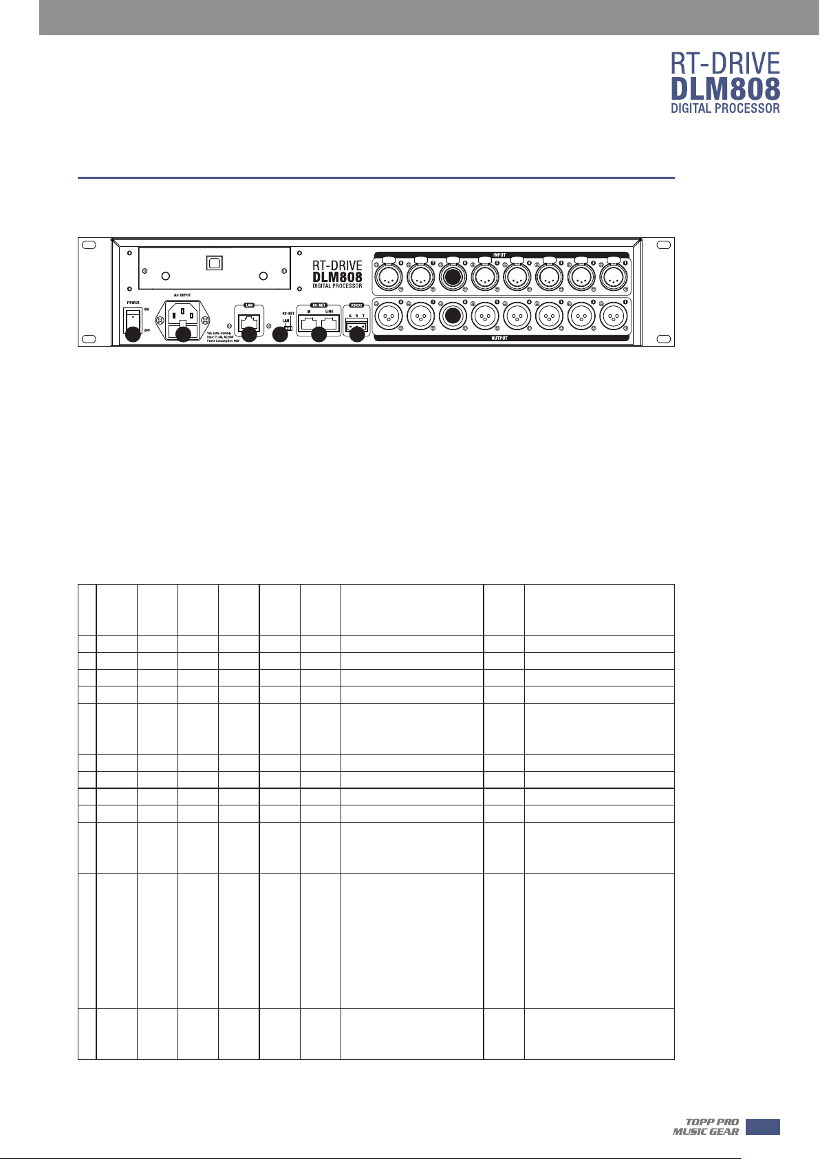
Rear Panel
8
9
11121316 15 10
8. MIC Input Port1~8
3 poles XLR input. These ports are used for connecting input device of analog microphone or line
input devices. Please be sure that MIC input port supports phantom power.
9. XLR Output Port 1~8
These ports are used for connecting analog line output device, such as Amplifier and Speaker.
10. RS-232 Input Port
It can connect other device via RS232 data line, T represents Transmitting end, R represents
receiving end, while G represents ground. DLM808 can control this device’s action. Such as
selecting two audio channel or mute whole system by device connected to this port.
Below table lists the whole command of RS-232:
5
Start
Start
Start
Byte0
Byte1
N0.
(1Byte)
(1Byte)
1 0x01 0x20 0x03 8 0x01 (1…8) (0---80)
2 0x01 0x20 0x03 8 0x02 (1…8) 0x40 Change Input channel Phase
3 0x01 0x20 0x03 8 0x03 (1…8) 0x40 Change Input channel Mute
4 0x01 0x20 0x03 8 0x04 (1…8) 0x00 0x40 Get Input channel Status
5 0x01 0x20 0x03 8 0x04 (1…8) 0x40
6 0x01 0x20 0x03 8 0x05 (1…8) 0x40 Change Output channel Gain
7 0x01 0x20 0x03 8 0x06 (1…8) 0x40 Change Output channel Phase
8 0x01 0x20 0x03 8 0x07 (1…8) 0x40 Change Output channel Mute
9 0x01 0x20 0x03 8 0x08 (1…8) 0x40 Get Output channel Status
10 0x01 0x20 0x03 8 0x08 (1…8) 0x40
11 0x01 0x20 0x03 24 0x09 (1…8)
Byte2
(1Byte)
Length
Comma
nd
(1 Byte)
Channel
(1Byte)
Value
(N Bytes)
(0---1)
(0---1)
Byte 0: Gain value
Byte 1: Phase value
Byte 2: Mut
Byte 0: Gain value
Byte 1: Phase value
Byte 2: Mute value
Byte 0:Mixer Input channel 1
Byte 1:Mixer Input channel 2
Byte 2:Mixer Input channel 3
…
Byte 8:Mixer Input channel 8
Byte 9:Mixer Digital Input 1
Byte 10:Mixer Digital Input 2
…
e value
(0---80)
(0---1)
(0---1)
0x00
End
Byte2
(1Byte)
0x40 Change Input channel Gain
Dev
channel status
Device output the Output
channel status
Set Output channel Mixer
0x40
From the input
function
ice output the input
12 0x01 0x20 0x03 8 0x0A (1…8) 0x00 0x40
Set Output channel Mixer
Status
7
Page 8
5
Rear Panel
Byte 0:Mixer Input channel 1
Byte 1:Mixer Input channel 2
Byte 2:Mixer Input channel 3
…
13 0x01 0x20 0x03 24 0x0A (1…8)
14 0x01 0x20 0x03 24 0x0D 16Bytes ASCILL code 0x40 Set device name
15 0x01 0x20 0x03 8 0x0E 0x00 0x40 Get Device information
16 0x01 0x20 0x03 29
17 0x01 0x20 0x03 8 0x0F Preset Number 0-32 0x40 Recall Preset
0x0E
Byte 8:Mixer Input channel 8
Byte 9:Mixer Digital Input 1
Byte 10:Mixer Digital Input 2
…
Byte 15:Mixer Digital Input 8
Byte 0-15 : Device name ,ASCILL
Byte 16: Firmware Version
Byte 17-21: Device Serial Number
11. RC-NET Input/Output Port
Control signal can transmit through this network port.
RC-Net is based on RS-485 transport protocol, which owns function of RS485 data exchange, to
realize large-scale real data transmit.
Device output the Output
0x40
Mixer status
Device output Device
0x40
information
12. LAN& RC-NET Switch
Use this switch to choice Network control way, you can determine to control it by Ethernet or
RC-NET.
13. LAN Network Control Port
DLM808 can connect with Ethernet switch via this port. On LAN network control port, you can
see two LEDs, they are connection status indicator (green) and signal transmit indicator(yellow).
-- If the yellow LED goes out, means no signal transmits; while if yellow LED is on, but green one
goes out, means the device detects network, but no connection.
-- If green LED is on ,means network connects well.
14. Optional Module
Usually it is prepared for DANTE module to insert in, which can be used for audio input/output
expansion.
15. Power Inlet
Connect AC voltage,100-240VAC,50-60Hz.
16. Power Switch
Press it to turn on/off the device.
8
Page 9
DSP Control
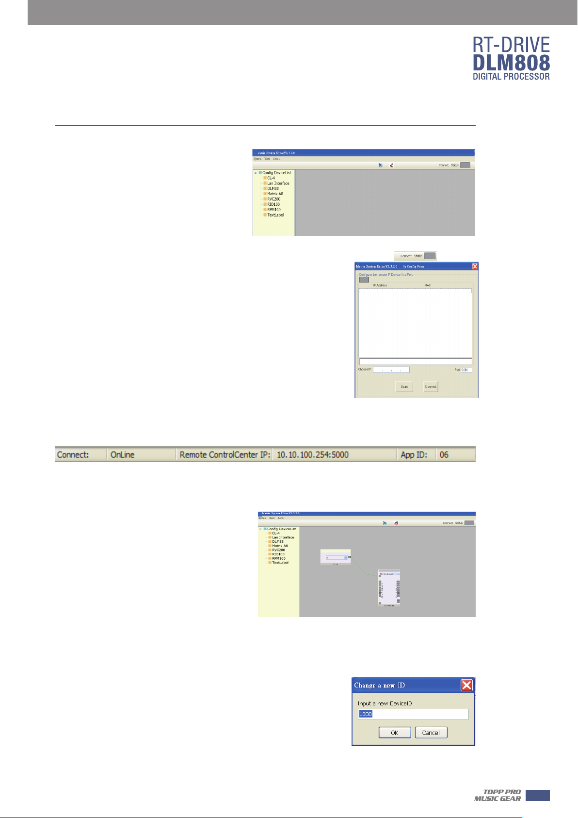
DLM808 can connect with PC by internet
port on router, or by CL-4. After successfully
connected, please click the file named
MatrixPro.exe on PC, you can see initial page
as below picture shows, which can set
connection of each device.
1. Configuration of IP Address
When connect DLM808 with PC by internet port on router:
Before connect devices on software control page, please set IP
address of DLM808 and router first, below gives steps(pay
attention that the toggle switch on DLM808 rear panel should be
at LAN side):
1). Click “Connect” control on top right corner, a search dialog will
jump up, click “Scan” button, it will automatically search IP and
MAC address in the system, as below picture shows. Then click
“Connect” button to build communication. The “Status” control in
top right corner indicates the communication status, which will
light green if connect right, while off means fail to connect.
6
2). If fail to connect following above step, then please key the IP address in “Choose IP” text field,
then click “Connect” button. After connecting successfully, you can see device information in the
lower-left corner, as below picture shows.
2. Configuration of Device Connection on Initial Page
Below picture shows you the connected status between CL-4 and DLM808.
How to connect?
1). Add Device
Hold to click CL-4(or Lan Interface) under
“Config DeviceList” and drag it to the
middle area, then release mouse, the CL-4
will be added to this area, use the same way
to add other devices.
2). Delete Device
Right-click the device, select “Delete
Module” to delete it.
Note: Before delete the device, please make sure that all the lines that connected to the selected
device have been removed, or you may fail to delete it.
3). Configuration of Device ID
Right-click the device, select “Change DeviceID” , a dialog appears
as below picture shows,input a new Device ID in the text field,
then click “OK” button to change it.
Note: The new ID you key in must be the same as it is showing on
DLM808’s LCD screen.
After successfully connected devices, double click DLM808 on this initial page to enter DSP
control page, which will be introduced later.
9
Page 10
6
DSP Control
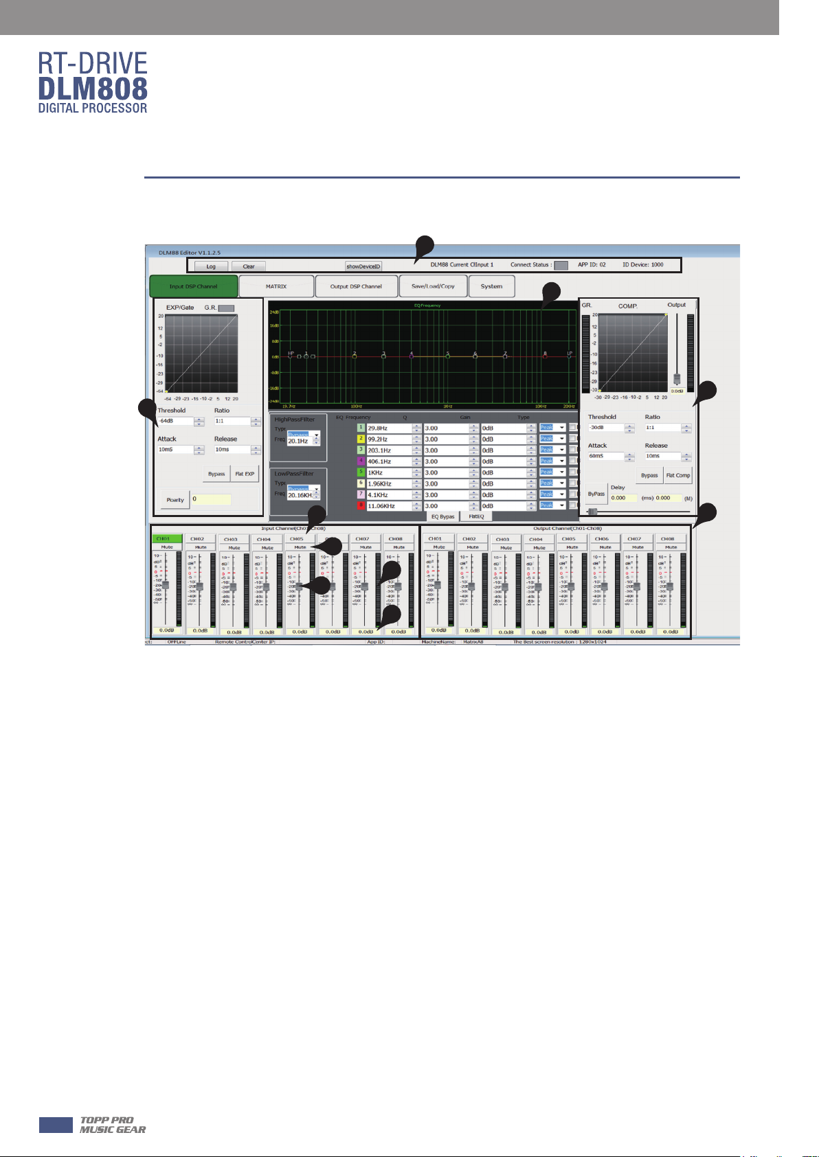
3. Input DSP Channel
1
3
4
2
5
6
8
7
9
1). Device Data
After connecting PC with DLM808 and communication right, here you can see information about
current channel, device name, ID number etc. If Connect Status icon is green, means
communication is right; While off means communication is fault.
2). Expander/Gate
In this area, you can adjust parameter of EXP/Gate , the curve in coordinate will change with
parameter’s change.
The Expander is used for adding input dynamic range according to user’s demand.
- Threshold
Click the control to set Gate threshold of selected channel. This threshold value determines the
open level of Gate. Actually, all input audio signal that higher than threshold value can go
through, the range of threshold value is -64dB to 20dB.
If input signal is lower than threshold, the Expander can enlarge it with setting ratio, then output
the signal.
If input signal is larger than threshold, output signal will be the same with input signal, which
means ratio is 1:1.
If adjusting the ratio to max(∞), Expander will change to noise Gate.
10
10
- Ratio
Click the control to set ratio of input signal to output signal. That is the dynamic change value of
Expander’s input signal/dynamic change value of Expander’s output signal.
Page 11

DSP Control
- Attack
Click the control to set the interval time from selected channel’s signal beyond threshold to open
noise Gate, the time can be set from 10 to 150ms.
Signals that increase slowly need lower attack, because if set the attack value too high, it may
cause “click” noise. Actually, all Gate may cause “click” noise when operation, but it can be avoid
if set properly.
- Release
Click the control to set the amount of time for the gate to go from open to fully close. It can be
set from 0.01 to 1 second.
Note: A fast release abruptly cuts off the sound once it has fallen below the threshold, A slower
release smoothly changes from open to closed, much like a slow fade out. If the release time is
too short, a click can be heard when re-open the gate .
- Bypass
Click Bypass, it will illuminate red, all input signals will bypass control of Threshold, Ratio, Attack
and Release to flow to next block, these parameters can not be adjusted.
- Flat EXP
Click this button to flat all set parameters to be default.
- Polarity
Click this button to invert the phase of the selected channel's signal (to alter the phase by 180°).
If the phase reverse is active the button will illuminate. The Polarity control can be used to correct
audio signals which are out of phase as well as to cancel/reinforce each other.
6
3). Equalizer
In this area, you can adjust parameter of Equalizer(EQ) , the curve in coordinate will change with
parameter’s change. EQ can compensate and correct frequency characteristic, through which to
make its frequency response characteristic curve to be more smooth and straight. On DLM808,
you can adjust 8 band EQ.
- High Pass Filter
This is a high-pass filter. It can pass higher frequencies. When set to its lowest position, the filter
is off.
Type indicates the filter’s type that you selected, different type means different shape and
different filter frequency range.
- Low Pass Filter
This is a low-pass filter. It can pass lower frequencies. When set to its highest position, the filter
is off.
Type indicates the filter’s type that you selected, different type means different shape and
different filter frequency range.
- EQ Frequency
Click the control to set the center frequency of the equalizer's
Low/Low-mid/High-mid/ High band separately. The center frequency is the middle of the
pass-band between the lower and upper cutoff frequencies which define the limits of the band.
The center frequency can be set from 20Hz to 20K Hz.
11
Page 12
6
DSP Control
- Q
Click the control to set the Q for the Low/Low-mid/High-mid/High band separately. The Q is the
ratio of the center frequency to the bandwidth. If the center frequency is constant, the
bandwidth is inversely proportional to the Q, which means that if you raise the Q, the bandwidth
will be narrowed. It can be adjusted from 0.4 to 24.
- Gain
Click the control to set the gain attenuation or boost at the center frequency for the
Low/Low-mid/High-mid/High band separately. It can be set from -24 to +24 dB. When Gain is
0dB, center frequency and Q are all invalid.
- Type
To select current filter type of current EQ, option is Peak/L.Shelf/H.Shelf.
- EQ Bypass
Click this button to bypass all signal to next block, if EQ bypass function is active the button will
illuminate. If it is not active,signal will be processed at this block and then flow to next block.
- Flat EQ
To flat all setting parameters to default.
4). Compressor
In this area, you can adjust parameter of compressor. Compressor will compress signal that
higher than threshold with specified ratio, then output it. The curve in coordinate will change
with parameter’s change.
-Threshold
Click the control to set the compressor threshold for selected channel.
If amplitude of an audio signal exceeds a certain threshold, the compressor will reduce the level
of this signal with specified ratio;
If amplitude of an audio signal is lower than this given threshold, compressor won’t work, signal
will flow to next block directly.
If setting ratio to “+∞”, compressor will be limited.
Threshold can be set from -30dB to 20dB.
- Ratio
Click the control to set the compression ratio for selected channel. The ratio determines the
amount of gain reduction. For example, a ratio of 4:1 means that if input level is 4 dB over the
threshold, the output signal level will be 1 dB over the threshold. The ratio can be set from 10:1
to 1:1 until limit.
- Attack
Click the control to set the compressor's attack setting for selected channel. The attack setting is
the period when the compressor is decreasing gain to reach the level that is determined by the
ratio. You can set the attack from 10 to 150 milliseconds.
- Release
Click the control to set the compressor for selected channel. Release sets the length of time the
compressor takes to return to its normal gain once the signal level drops below the threshold.
Release can be set from 10 to 1,000 milliseconds.
12
Page 13

DSP Control
- Bypass
Click this button to bypass all signal to next block, if compressor bypass function is active the
button will illuminate. If it is not active,signal will be processed at this block and then flow to next
block.
- Flat COM
To flat all setting parameters to default.
- Delay
Delay here can engage and disengage the delay function for selected Channel. Move the slide
below it to set delay time. Only if delay function is active can set the delay time. If Bypass beside
it is enable, the parameter can not be adjusted.
5). Current input channel selection
Click channel button 1-8, corresponding background LED will light, which means current channel
is selected, you can set parameters on this channel.
6). Input channel mute control
Click it, the background LED will light, which means it enable mute function on current channel.
7). Input channel Meter control
Select the block and slide it to adjust current channel’s volume.
6
8). Input channel Meter dynamically indication
Dynamically indicate current channel’s input level meter.
9). Input channel Meter value display
The value will vary with slide moving.
10). Output channel control
Function in this area is similar to that to input channel. Please read carefully about input channel
introduction.
13
Page 14
6
DSP Control
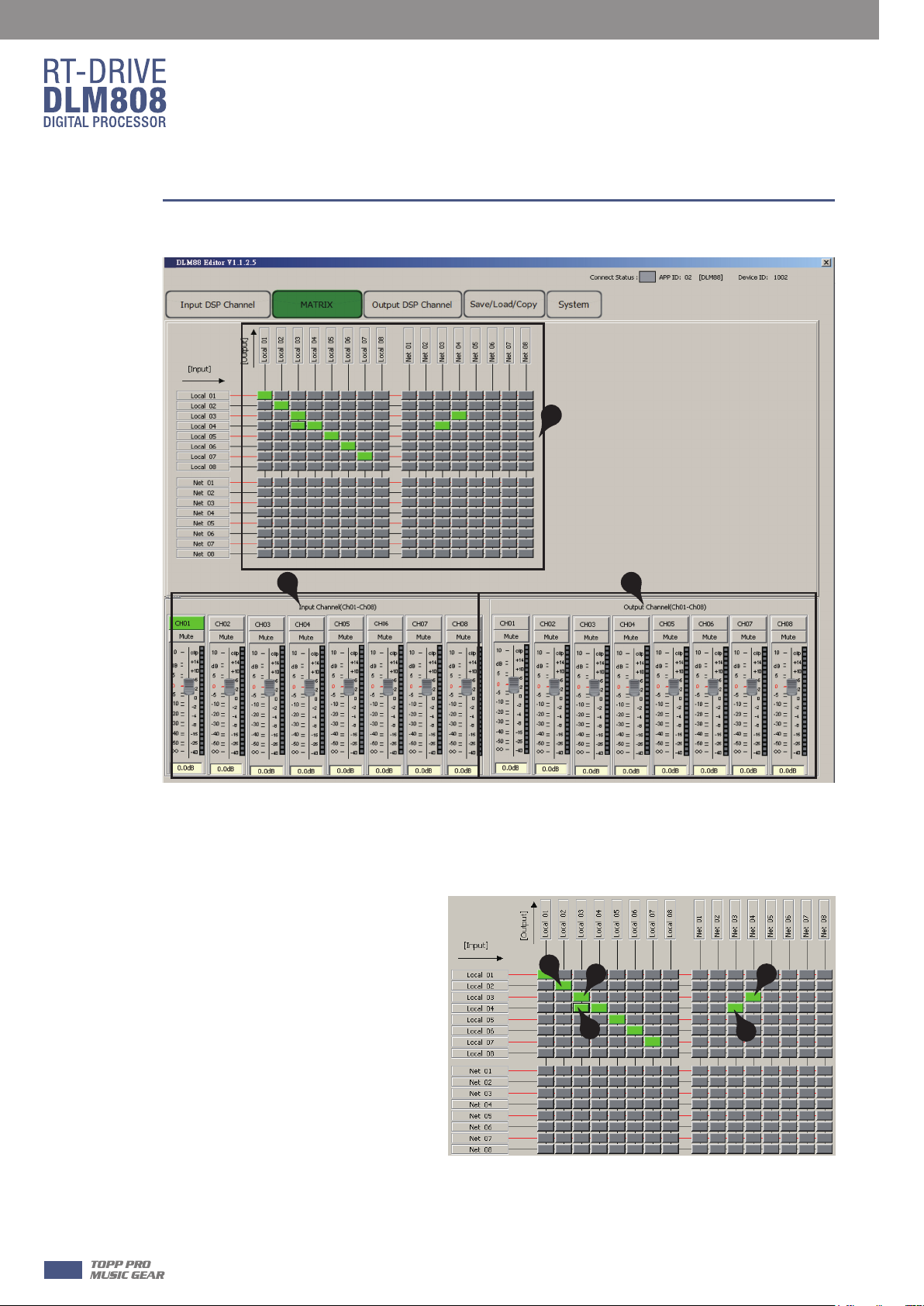
4. MATRIX
1
2 3
1). Assign of input and output channels
In this area, there are many small blocks, click one block, its background turns green, audio signal
flow from left input channel to top output channel; while the signal won’t go through any
channel if it is not active. Below figure gives an example:
a. Click the block as a marked, its
background turns green, means that
signal input from channel Local 02 will
be assigned to output channel Local
02. But the input channel Local 02
wouldn’t be assigned to other output
channels because there is no other
block activates.
b&c. Click the block as b&c marked,
their background turn green, means
that signal input from channel Local
03 and Local 04 will be assigned to
output channel Local 03. Other
channels that inactive won’t be
assigned to any other output channel.
d&e. Click the block as d&e marked, their background turn green, means corresponding input
channel signal will be assigned to corresponding output channel.
And so on...
a
c
b
d
e
14
Page 15
DSP Control
2). Input Channel Parameter Control
Please refer to section 4.3 Input DSP Channel for details about this area.
3). Output Channel Parameter Control
Please refer to section 4.3 Input DSP Channel for details about this area.
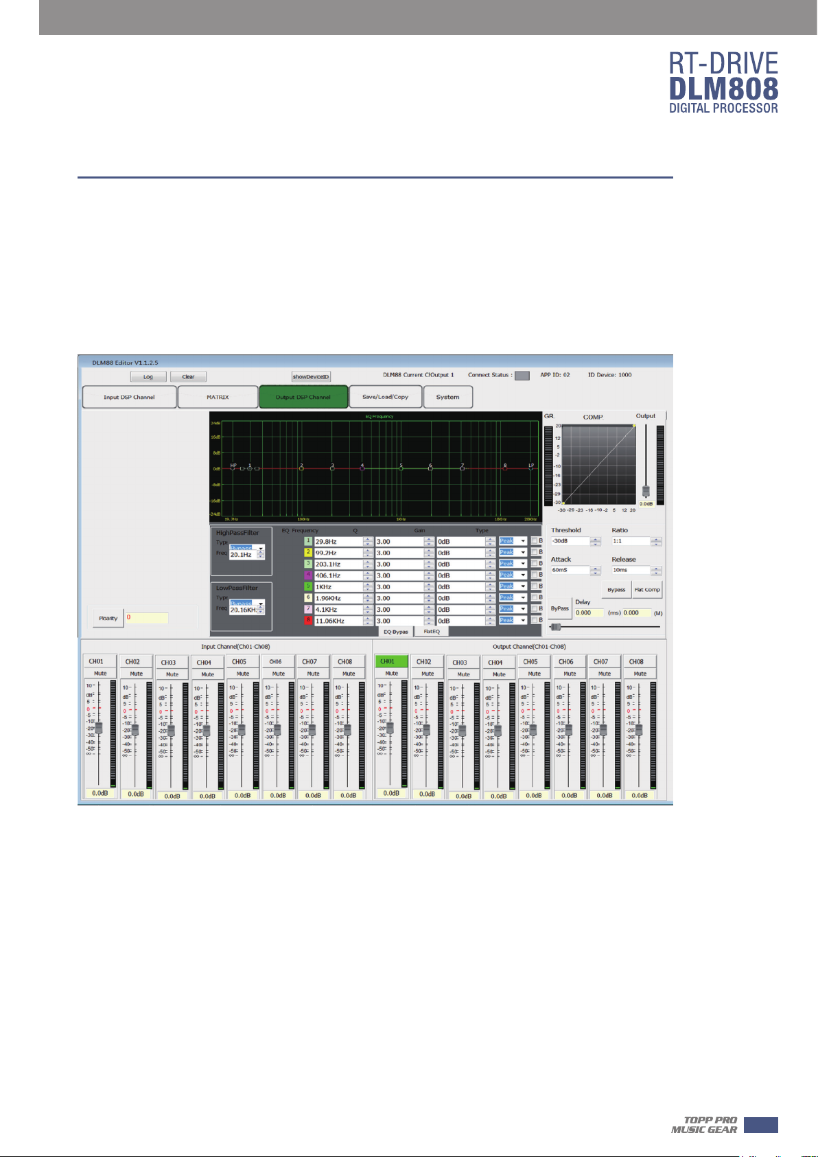
5. Output DSP Channel
6
As you can see, compared with input DSP channel, this page only remove the Gate/EXP function,
please refer to section 4.3 Input DSP Channel for details about its function.
15
Page 16
6
DSP Control
6. Save/Load/Copy
1
2
3
4
16
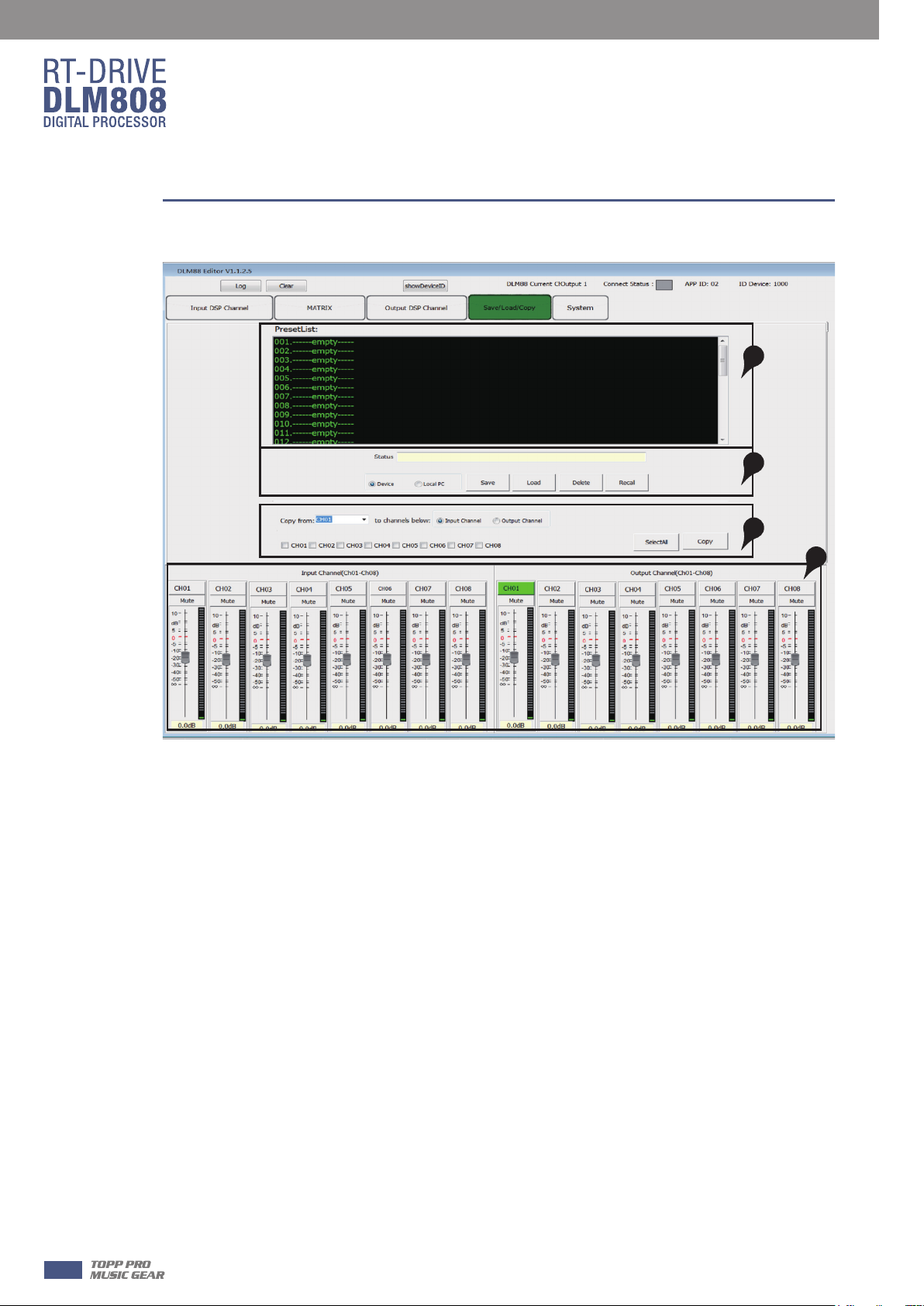
1). Preset List
The text area shows preset list that have been saved, select a preset, then click Load button to
load the selected preset to corresponding control.
2). Save/Load/Delete/Recall
When use this function, please pay attention the switch of Device and Local PC first. If Device is
selected, Save and Load buttons are not enabled, which means you can not save or load presets
from Device to PC. While they are enabled if select Local PC.
-Save
In Local PC mode, select a preset in Preset List, then click Save button to save the selected preset
from Local PC to DLM808.
-Load
In Local PC mode, select a preset in Preset List, then click Load button to load the selected preset
from Local PC to DLM808.
-Delete
In Device mode, select a preset in Preset List, then click Delete button to delete the selected preset
from DLM808.
-Recall
In Device mode, click Recall button to recall all the presets in Preset List.
3). Copy
Select a channel that you want to copy to other channels from item menu, such as CH01, then
select Input Channel or Output channel, select the channels that you want to be copied or click
SelectAll button to copy CH01 to these channels.
4). Input/Output Channel Parameter Control
Please refer to section 4.3 Input DSP Channel for details about this area.
Page 17
DSP Control
7. System
1
6
2
3
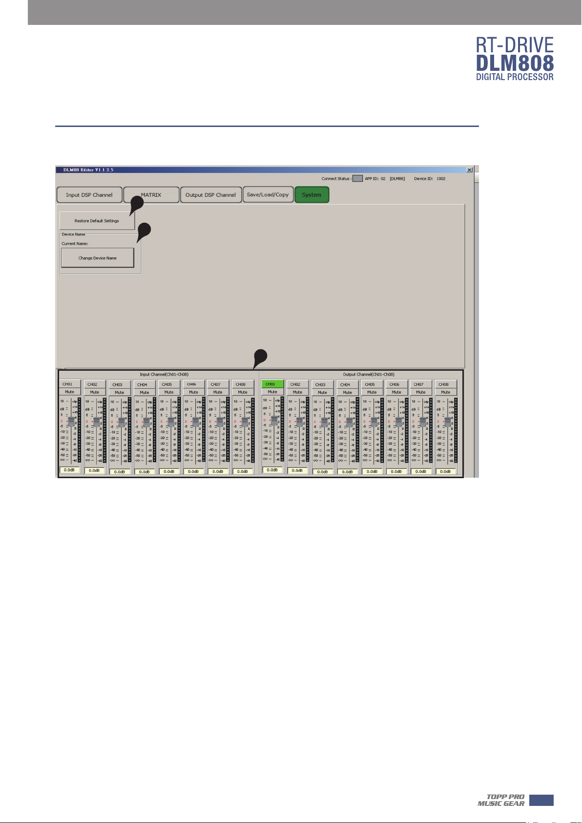
1). Reset Factory
Click this button to reset all setting parameters to default.
2). Change device name
Click this button to change current device name in the dialog that pops-up.
3). Input/Output Channel Parameter Control
Please refer to section 4.3 Input DSP Channel for details about this area.
17
Page 18
7
Web Configuration of LAN Module
Web Configuration of LAN Module
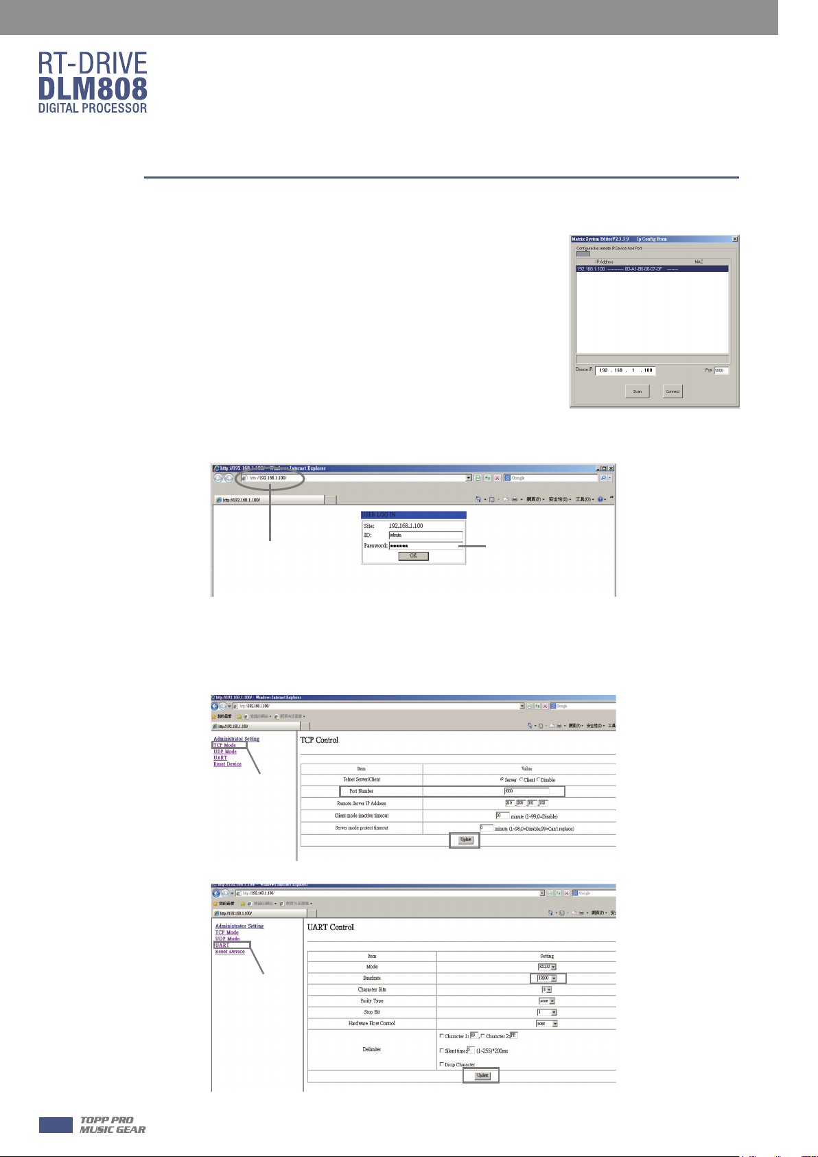
1. Search IP address of LAN module by PC software.
2. Open the browser on PC , input IP that searched in above step to enter the configuration web
site.
Device IP
Below pictures show the configuration and review for port number and Baud rate.
3. Please DO NOT change the Baud rate and TCP PORT, while you can change any other
parameters. Then click “Update” and restart device.
TCP Mode page
Default password:system
Change confirm
18
Current uart page
Change confirm
Page 19
Technical information
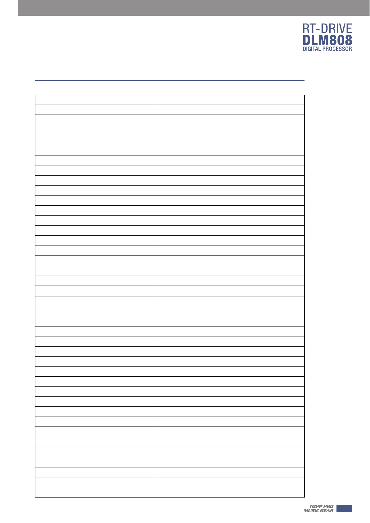
Microphone input Electronically balanced
Frequency Response to Main Output 20Hz~20KHz at 0dBu ±1dB
Distortion(THD&N) to Main Output <0.01% at 0dBu 1KHz
SNR(Signal to Noise Ratio) 110dB
Maximum Input Level +20dBu
AUX1~8 Outputs
Maximum Output Level +20dBu
System Crosstalk
Input to Output -87dBu
Adjacent Channels -87dBu
Noise Gate
Threshold Range -84dBu - 0dB
Attack time 0.5mS ~ 200mS
Relesae time 5mS~2S
8
Compressor
Threshold
Attack time 10mS ~ 150mS
Relesae time 10mS~1S
Ratio 1:1 to 24:1
Gain 0dBu - +24dB
EQ
Low (LowPass or LowShelf) 21Hz~19.2KHz +/- 24dB
Low Mid 21Hz~19.2KHz +/- 24dB
High Mid 21Hz~19.2KHz +/- 24dB
High(HighPass or HighShelf) 21Hz~19.2KHz +/- 24dB
Digital Audio
ADC Dynamic Range 114dB
DAC Dynamic Range 114dB
DSP Processor 32-bit , floating point
Sample Rate 48K/24bit
Range -30dBu -+20dB
Impedances
operating free-air temperatu
storage temperature range -20℃~60℃
re range 0~40℃
19
Page 20
9
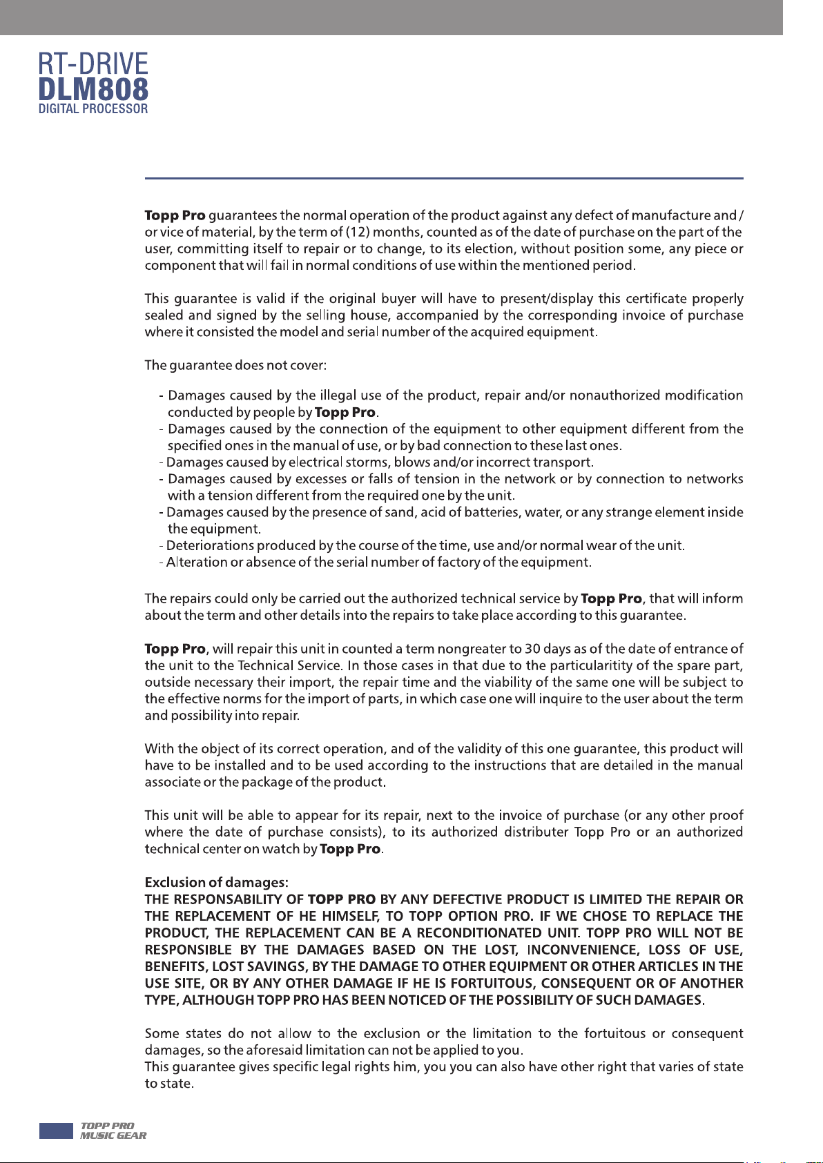
Guarantee
20
Page 21
Notes
10
21
Page 22
6
Notes
22
Page 23
Notes
6
23
Page 24

Page 25
TOPP PRO
NF04784
說明書-英文
RT-DRIVE DLM808 TOPP PRO_V1.0
RT-DRIVE DLM808
0.08KG /1
銅板紙
6
2016.09.14
12
 Loading...