

T2208
16 mic preamplifiers with dedicated trim control
Volume
2

Important Safety Instructions
* T2208, are mixers for professional use. They can be used in following electromagnetic
environment: residential, commercial and light industrial, urban outdoors.
They are the apparatus not intended for rack mounting.
* The peak inrush currents equal to 8.33 A.
*This device complies with part 15 of the FCC Rules. Operation is subject to the following two
conditions: (1)this device may not cause harmful interference, and (2)this device must accept any
interference received, including interference that may cause undesired operation. Changes or
modifications not expressly approved by the party responsible for compliance could void the
user's authority to operate the equipment.
NOTE: This equipment has been tested and found to comply with the limits for a Class B digital
device, pursuant to Part 15 of the FCC Rules. These limits are designed to provide reasonable
protection against harmful interference in a residential installation. This equipment generates,
uses and can radiate radio frequency energy and, if not installed and used in accordance with the
instructions, may cause harmful interference to radio communications. However, there is no
guarantee that interference will not occur in a particular installation. If this equipment does cause
harmful interference to radio or television reception, which can be determined by turning the
equipment off and on, the user is encouraged to try to correct the interference by one or more of
the following measures:
-- Reorient or relocate the receiving antenna.
-- Increase the separation between the equipment and receiver.
-- Connect the equipment into an outlet on a circuit different from that to which the receiver is
connected.
-- Consult the dealer or an experienced radio/TV technician for help.
3
Index
3
4
2
7
8
9
10
11
12
13
14
38
1
26 27
16
25
17
18
21
32
22
23 24
32
34
32 33
20
32
19
35
36
28 29 30
6
15
31
37
5
40
50
49
42
48
43 44
45
41
39
46
47
Page7: 1. Select button
Page8: 5. Mixer/Long Faders button
Page9: 6. Meters button
Page10: 8. Gate/Comp button
Page11: 10. FX1-2 button
Page12: 12. 48V Phantom button
Page13: 14. DCA button
Page14: 16. Assign to Main button
Page15: 23. Mute button
Page16: 28. FX1/FX2 send
Page17: 35. Control Room knob
Page18: 39. Line inputs 17-20
4. LED meters
7. Assign/Channel button
9. EQ button
11.Digital In/Out button
13. System/Routing button
15. DCA1-6 buttons
22. Link button
27. FX1-2 select buttons
34. Parameter Adjust knob
38. Combo Jack
50. Optional module
4
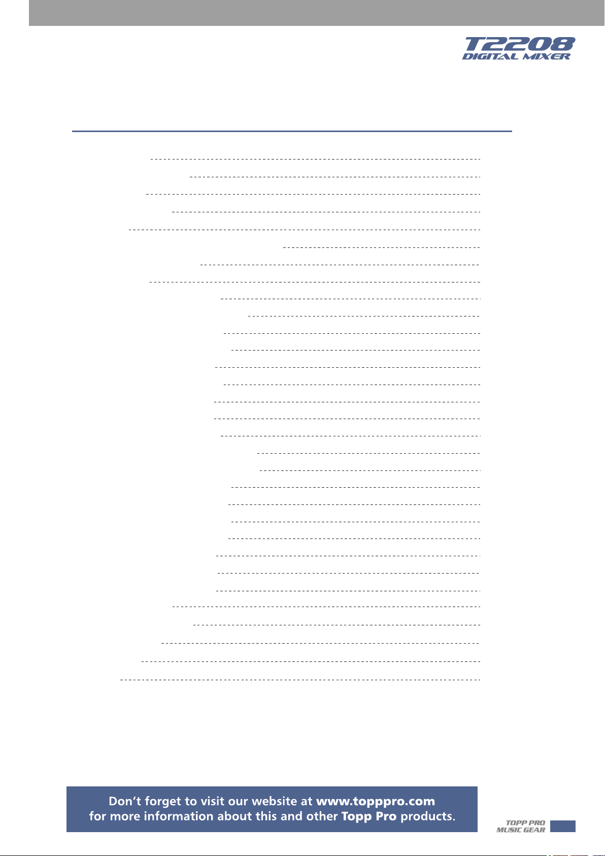
Table of contents
1 Introduction
2 Summary of features
3 Useful data
4 Software Update
5 Control
5.1 Function Buttons and Knobs
5.2 Rear Panel
6 DSP Control
6.1 Mixer interface
6.2 Long Faders interface
6.3 Assign interface
6.4 Channel interface
6.5 Gate interface
6.6 COMP interface
6.7 PEQ interface
6.8 GEQ interface
6.9 FX1-2 interface
6.10 Digital Input interface
6.1 1 Digital Output interface
6.12 DCA Set interface
6.1 3 Meters interface
6.1 4 Routing interface
6.1 5 System interface
6.1 6 Load interface
6.1 7 Copy interface
6
6
6
7
7
7--17
17--18
19
19
21
22
25
26
28
29
31
32
34
35
35
37
38
39
41
42
6.1 8 Save interface
7 Hookup Diagram
8 Technical information
9 Block Diagram
10 Guarantee
11 Notes
43
44
45
46
47
49
5
Introduction
1
2
Thank you for purchasing the TOPP PRO T2208 digital mixer. With 20 line-level inputs, 16
microphone preamplifiers and playback engine; processing with 31-band GEQ, compressor, gate,
delay, polarity; DSP effects; aux buses; subgroups; sensitive LED metering; load/save/copy mixer
setting; remote control, USB in and more, the T2208 helps you creating a wonderful show. It is
easy to operate though it has powerful function.
We suggest that you use this manual to familiarize yourself with the features and applications for
your T2208 before using.
Summary of Features
- 16 microphone preamplifiers with dedicated trim control
- 20 line-level inputs
- 8 Aux sends
- 2 internal FX
- 1 stereo main out
- All channels Control Room outputs
- 2 headphones output
- USB Stereo recording
- 100mm precision motor fader
- 7 inch color LCD touch screen for graphical view and setup
- 24-bit/48KHz sampling rate
- Program, save, load & copy functions
- Digital noise gate
- Digital compressor/limiter
- Digital 4-band full parametric EQ
- PAN
- Phase reverse
- Time delay
- 6 DCA for Digital Control Audio or MUTE
- Lock and unlock function
- Change the password
- Remote Control: Ethernet or USB
- iPad App T2208 editor for wireless control
- Expand socket for option module: Multi-track USB audio recording module or CobraNet
module or Dante module etc
3
6
Usefull Data
Please write your serial number here for future reference.
Software Update
We will always update the T2208 software, please download the latest version from below sites:
www.topppro.com
Since function of T2208 will also change when you update the software, this manual can help
you familiar with the basic function, for the precision, please refer to the real T2208 digital mixer.
Note: When you update the firmware, all the parameters you had saved in the mixer may be
destroyed.
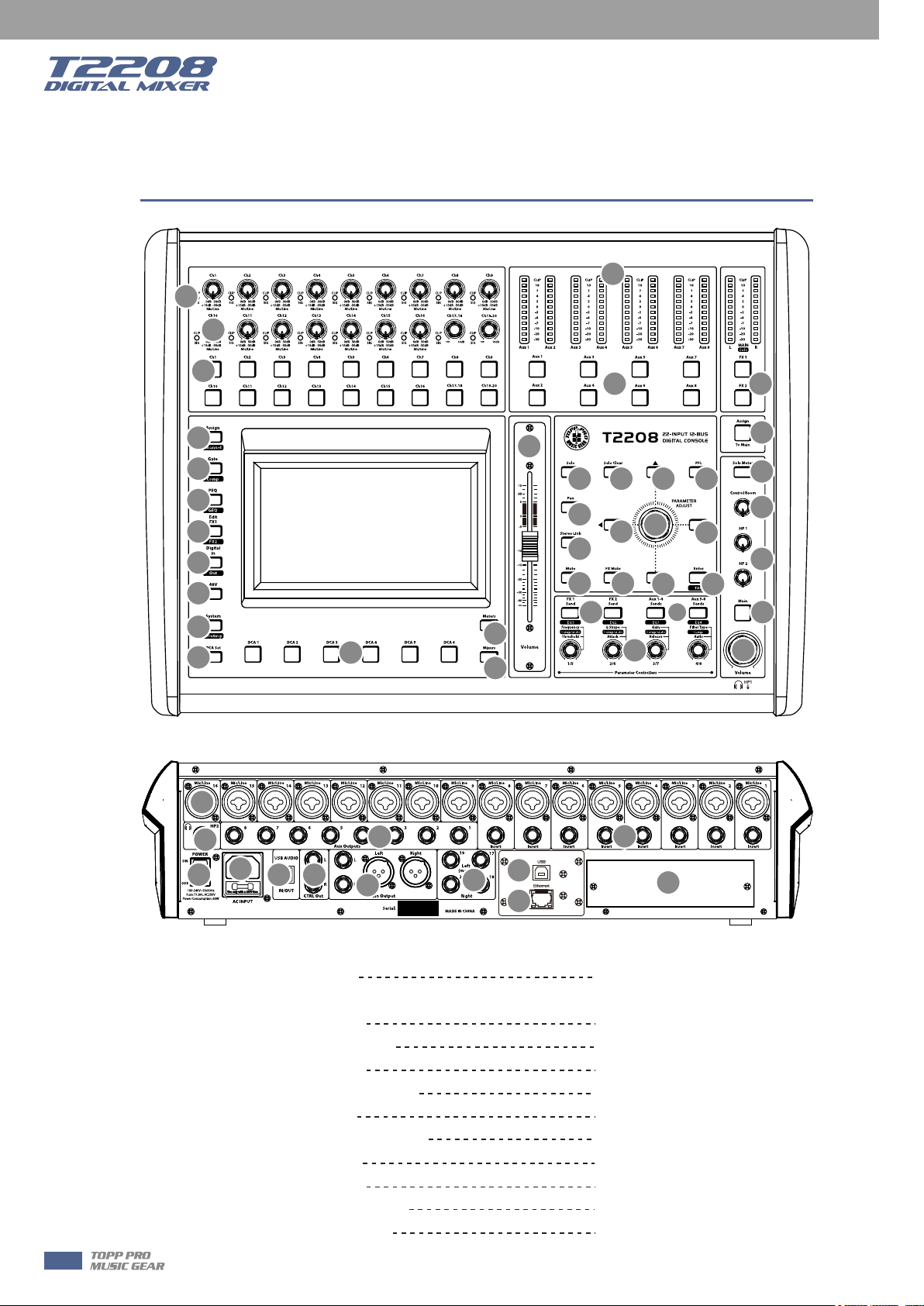
Control
5.1 Function buttons and knobs
3
2
1
4
4
5
1. Main input channel select buttons
There are 18 select buttons Ch1-20 as you can see on the panel.
Press this button will route its channel to add DSP setting and assign its output. It will illuminate
as has been pressed and enabled. In DCA window, you can select group channels by this button.
2. Main input channel knobs
˙The knob Ch1-16 control the gain level of the channel's input.
Note: It is very important to properly set the level of the input gain to minimize noise and avoid
overload distortion.
˙The knob Ch17-20 control input level of the channels.
3. Main input signal clip indication
These LEDs beside input channel knobs indicate the input level of Channel1-20.
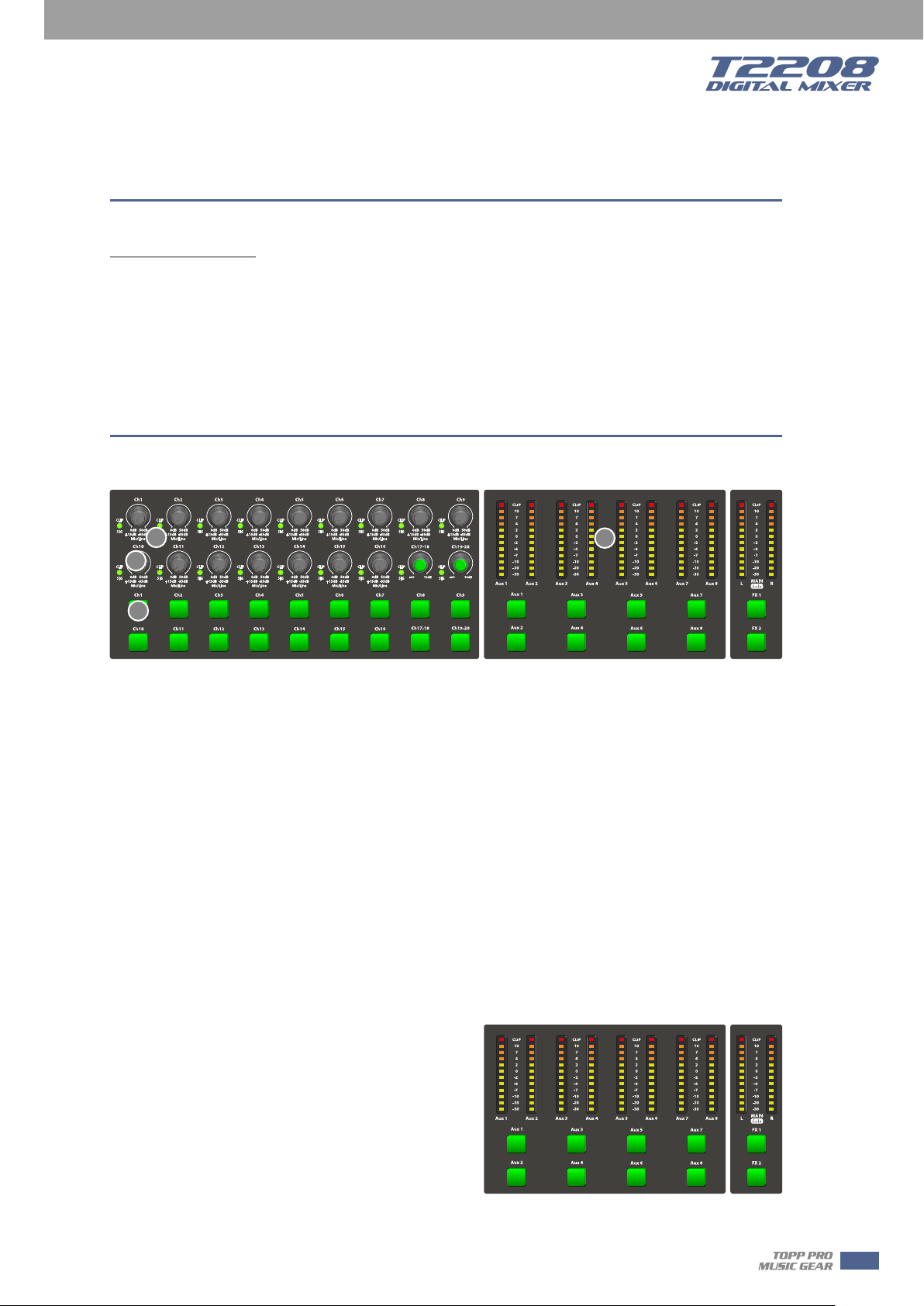
4. LED meters
The LED meters show the signal status, including the output level.
˙AUX1-8 & Main
Indicate the output level of AUX1-8 & Main. Please
be aware only AUX1-8 and Main button engaged
can light the corresponding meters.
˙AUX1-8 button
When the buttons are off, the meters above them
won’t light, while illuminated can light the meters.
˙Main/FX1/FX2/Solo meters
Indicate the input level of Main/FX1/FX2/Solo. Please be aware only FX1/FX2 or Solo meter button
engaged can light the corresponding meters.
7
Control
5
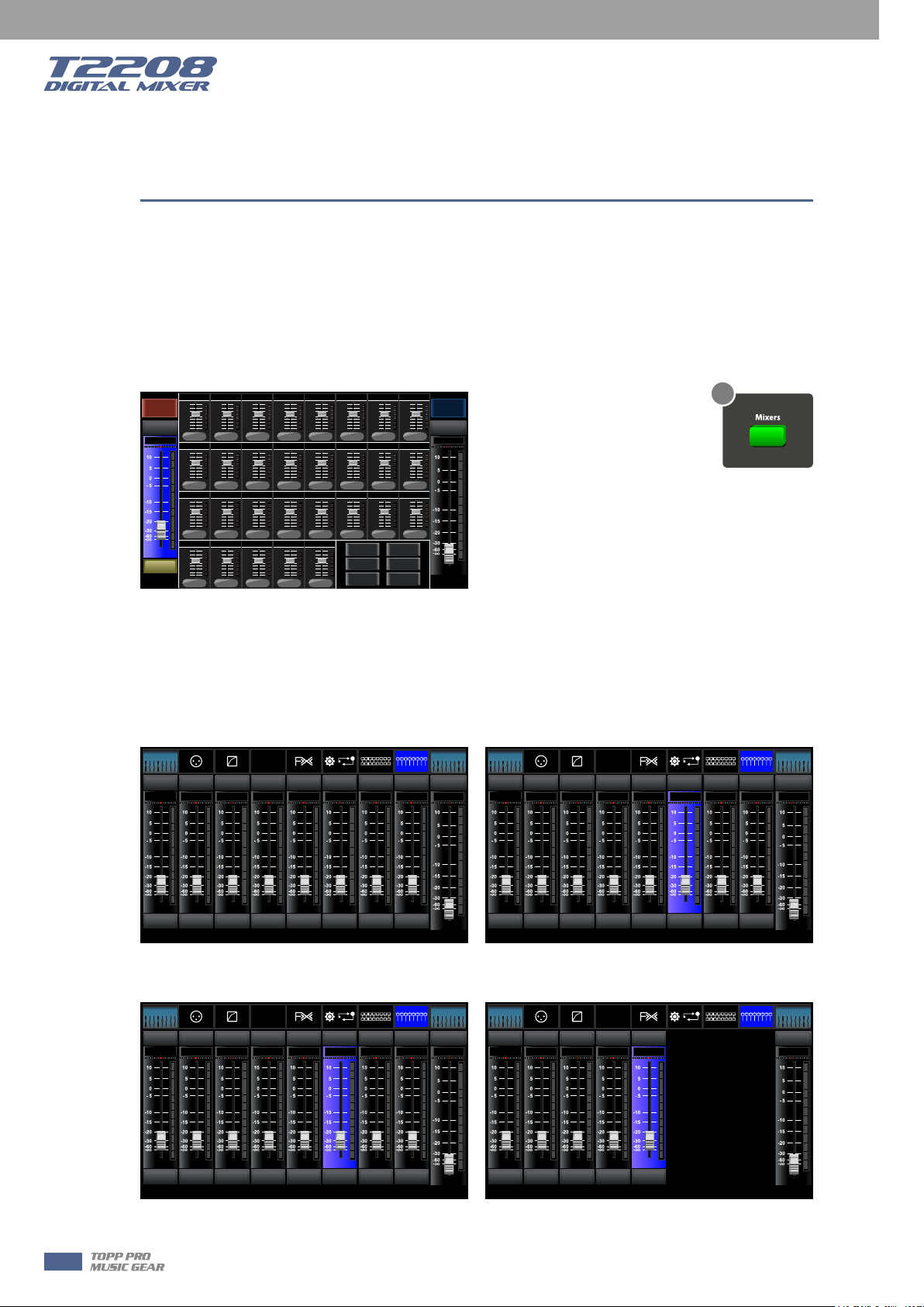
5. Mixer/Long Faders button
Press this button twice, it will switch between Mixer and Long Faders function.
˙Mixer
Press this button, you will see mixer page on LCD screen, where you can control all the input and
output channels’ level, solo and mute, as well as DCA group level control, the window is as
below.
For the detail operation, please refer to the introduction in section 6.
-10dB
-10dB
-10dB
-10dB
-10dB
-10dB
Ch11Ch10Ch09
Aux3
FX1 FX2
-10dB
-10dB
Ch12 Ch15Ch14Ch13
000
Aux4Aux2
000
-10dB
-10dB
Aux5 Aux6
-10dB
USBCh17-18
DCA
0
Mute Mute
-10. 5dB
CH01
Solo
Name
Ch02 Ch08Ch07Ch06Ch05Ch04Ch 03
Ch01
-10dB
-10dB
-10dB -10dB -10dB
-10dB
0
Aux1
-10dB
-10dB - 10dB -10dB
0 0
0
Ch19-20
-10dB
-10dB
-10dB
0000000
-10dB
-10dB
Aux7 Aux8
DCA 1 DCA 2
DCA 3 DCA 4
DCA 5 DCA 6
-10dB
Long Fader
0000000
-10dB
0
Ch16
-10dB
0000
Mixer Page
-10. 5dB
-10. 5dB
Main
Main
Name
Name
5
˙Long Faders
Press this button again, you will see Long Faders page on LCD screen, where you can control all
the input and output channels’ level, solo, mute, pan and rename the channel, as below pictures
show.
For the detail operation, please refer to the introduction in section 5.
Assign
Bank Select
Left
-10. 5dB -10.5 dB -10.5d B -10.5d B -10. 5dB-10. 5dB-10. 5dB-10. 5dB
Gate
Channel
Comp
MuteMut e Mute Mute Mute M ute Mut e Mu te Mute
FX 1
PEQ
EQ
GEQ
System
Routing
FX 2
All Faders
Bank Select
Long
DCA
-10. 5dB
Faders
Right
Assign
Gate
Comp
PEQ
EQ
GEQ
Bank Select
Left
Channel
MuteMut e Mute M ute Mut e Mu te Mute M ute Mute
-10. 5dB -10.5 dB -10.5d B -10.5d B -10. 5dB-10. 5dB-10. 5dB-10. 5dB
FX 1
FX 2
System
Routing
All Faders
DCA
Long
-10. 5dB
Faders
Bank Select
Right
CH01 CH0 2 CH03 CH 04 CH05 CH 06 CH07
SoloSolo Solo Solo Solo Solo Solo Solo
CH01 CH0 2 CH03 CH 04 CH05 CH 06 CH07 CH 08
CH08
Main
Main
CH09 CH1 0 CH11 CH 12 CH13 CH 14 CH15
SoloSolo Solo Solo Solo Solo Solo Solo
CH09 CH1 0 CH11 CH 12 CH13 CH 14 CH15 CH 16
CH16
Main
Main
- Page of input channel 1-8 - Page of input channel 9-16
Assign
Bank Select
Left
-10. 5dB -10.5 dB -10.5d B -10.5d B -10. 5dB-10. 5dB-10. 5dB-10. 5dB
AUX1 AUX2 AUX3 AUX 4 S UB1 SUB2 SUB3
AUX1 AUX2 AUX3 AUX 4 S UB1 SUB2 SUB3 SUB4
Gate
Channel
Comp
MuteMut e Mute M ute Mut e Mu te Mute M ute Mute
SoloSolo Solo Solo Solo Solo Solo Solo
FX 1
PEQ
EQ
FX 2
GEQ
System
Routing
All Faders
DCA
Long
-10. 5dB
SUB4
Faders
Bank Select
Right
Main
Main
Assign
Gate
Comp
PEQ
EQ
GEQ
Bank Select
Left
Channel
MuteMut e Mute M ute Mut e Mute
-10. 5dB -10.5 dB -10.5d B -10.5d B -10. 5dB-10. 5dB
CH17 -18 CH19 -20 FX1 FX 2 USB
SoloSolo Solo Solo Solo
CH17 -18 CH19 -20 FX1 FX 2 USB
System
Routing
All Faders
DCA
FX 1
FX 2
Bank Select
Long
Faders
Main
Main
Right
-Page of output channel AUX1-4/AUX5-8 - Page of input channel17-20/FX1-2/USB
8
Control
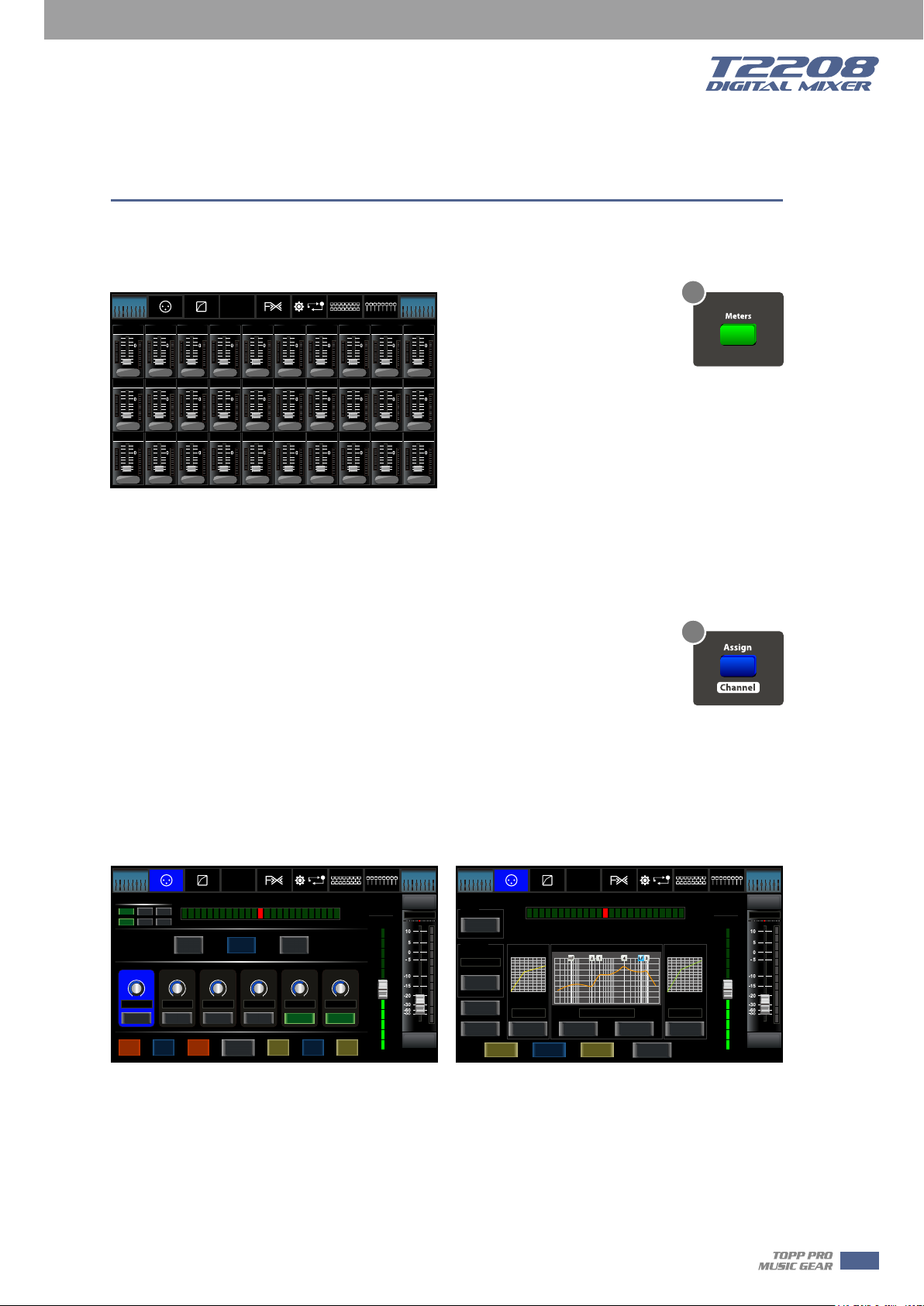
6. Meters button
Press this button to enter meters check page, as below picture show, for the details, please refer
to corresponding introduction in section 6.
Bank Select
Left
OFF
Lim
Ch01
OFF
Lim
Ch11
OFF
Lim
AUX5
Assign
Gate
Channel
Comp
OFF
Sig
Sig
Sig
OFF
Sig
Lim
Ch02
OFF
Lim
Ch12
OFF
Lim
AUX6
Sig
Lim
Lim
Ch03
OFF
Sig
Sig
Lim
Lim
Ch13
OFF
Sig
Sig
Lim
Lim
AUX7
FX 1
PEQ
EQ
OFF
Ch04
OFF
Ch14
OFF
AUX8
FX 2
GEQ
OFF
Sig
Sig
Sig
OFF
Sig
Lim
Lim
Ch05
Ch06
OFF
OFF
Sig
Lim
Lim
Ch15
Ch16
OFF
OFF
Sig
Lim
Lim
Ch17-18
Ch19-20
System
Sig
Sig
Sig
Routing
Lim
Lim
Lim
All Faders
DCA
OFF
OFF
Sig
Sig
Lim
Lim
Ch07
Ch08
OFF
OFF
Sig
Sig
Lim
Lim
AUX1
AUX2
OFF
OFF
Sig
Sig
Lim
Lim
FX1
FX2
Faders
OFF
Ch09
OFF
AUX3
OFF
USB
Right
OFF
Sig
Sig
Lim
Ch10
OFF
Sig
Sig
Lim
AUX4
OFF
Sig
Sig
Lim
Main
Bank Select
Long
Meters Page
6
7. Assign/Channel button
Press this button twice, it will switch between Assign and Channel function.
˙Assign
Press this button to enter assign page, signal from a selected input channel can
7
be assigned to Main, AUX1-4, AUX5-8 and FX1-2. The window is as below.
For the detail operation, please refer to introduction in section 6.
5
˙Channel
Press this button again, you will see Channel page on LCD screen. It gives you a preview of other
function such as Polarity, Delay, Link, Assign, Gate, EQ, Compressor etc.
You can also adjust corresponding parameters that show on the screen. But for Gate here, you
can only adjust threshold; For Compressor, you can only adjust threshold; For EQ, you can adjust
nothing here.
For the detail operation, please refer to introduction in section 6.
Assign
Channel
Link
Gate
Comp
Left
Main
AUX3
AUX2 AUX4AUX1
Phase
Bank Select
Left
DCA Assign
DCA 1 DCA 2 DCA 3
DCA 4 DCA 5 DCA 6
Assign
Sends
-10. 5dB -1 0.5dB -10.5dB -10.5d B -10. 5dB -1 0.5dB
PRE PRE PRE PRE
48V
PEQ
EQ
AUX1-4
Select
Channel
FX 1
System
Routing
FX 2
GEQ
Pan
AUX5-8
FX1
POST PO ST
Copy
Load
Channel
Assign Page Channel Page
All Faders
Right
Bank Select
Long
DCA
Parameter
-10.5dB
FX2
Save
Aux 1
Faders
Mute
-10. 5dB
CH08
Solo
CH08
Right
Bank Select
Left
Polarity
Delay Time
0.0m S
Assign
Gate
Channel
Comp
Left
INV.
Gate
Delay
Threshold Th reshold
Link
0.0d B 0.0d B
Main
ON
Load
Copy
Channel
FX 1
PEQ
EQ
GEQ
Pan
EQ
Rock Drums
ON
Save
FX 2
Flat EQ
System
Select
Channel
Routing
All Faders
DCA
Right
Compressor
ON
Long
Parameter
-10.5dB
Aux 1
Faders
Bank Select
Right
Mute
-10. 5dB
CH08
Solo
CH08
9
Control
5
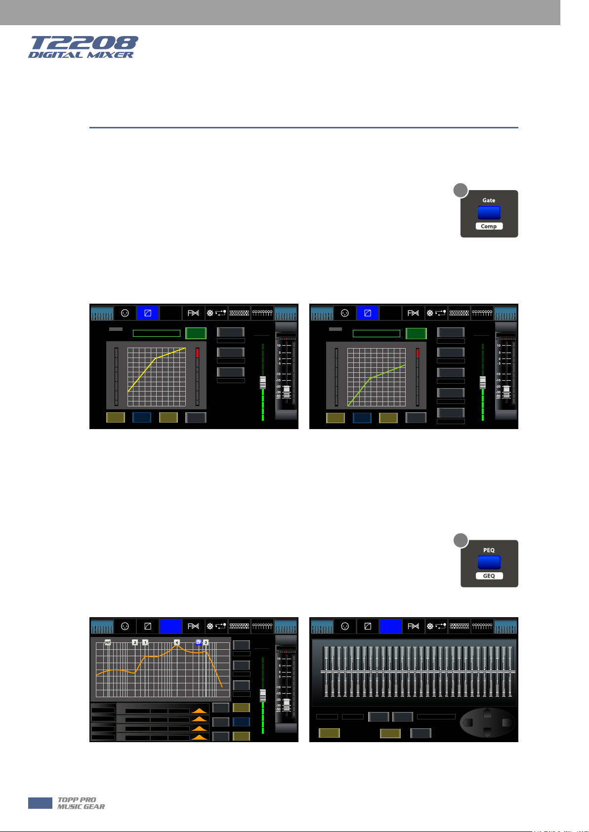
8. Gate/Comp button
Press this button twice, it will switch between Gate and COMP function.
˙Gate
8
Noise gate attenuates signals that below the threshold and allows signals to pass
through only when they are above a threshold setting. The window is as below.
For the detail operation, please refer to introduction in section 6.
˙COMP
A compressor reduces the level of an audio signal if its amplitude exceeds a certain threshold. The
window is as below.
For the detail operation, please refer to introduction in section 6.
Assign
Bank Select
Left
Channel
Gate
Comp
Gate
Level LIMIT
(dB)
CLIP
16
10
12
7
7
4
3
2
-1
0
-5
-2
-10
-4
-14
-7
-18
-10
-22
-20
-26
-30
-30
Copy
Load
Channel
Bank Select
Default
System
Routing
All Faders
Thresh old
0.0dB
Attack
50mS
Releas e
100mS
DCA
Parameter
Aux 1
-10.5dB
Mute
-10. 5dB
CH08
Solo
CH08
Right
Faders
FX 1
PEQ
EQ
Save
FX 2
GEQ
ON
(dB)
4
8
13
17
21
25
30
34
38
42
46
50
Select
Channel
Long
Assign
Channel
Gate
Comp
Bank Select
Left
Comp
Level LIMIT
(dB)
CLIP
16
10
12
7
7
4
3
2
-1
0
-5
-2
-10
-4
-14
-7
-18
-10
-22
-20
-26
-30
-30
Copy
Load
Channel
Default
PEQ
EQ
Save
Gate Page Comp Page
System
Routing
All Faders
DCA
Thresh old
0.0dB
Attack
50mS
Releas e
100mS
Comp Rat io
1:1
Comp Gai n
0.0dB
FX 1
FX 2
GEQ
ON
(dB)
4
8
13
17
21
25
30
34
38
42
46
50
Select
Channel
Long
Parameter
Aux 1
-10.5dB
Faders
Bank Select
Right
Mute
-10. 5dB
CH08
Solo
CH08
9. EQ button
Press this button twice, it will switch between PEQ and GEQ function.
˙PEQ
An equalizer is a filter that allows you to adjust the level of frequency in the range of 20Hz-20KHz.
The window is as below.
For the detail operation, please refer to introduction in section 6.
9
˙GEQ
In GEQ page you can set the 31-band EQ. The window is as below.
For the detail operation, please refer to introduction in section 6.
Assign
Bank Select
Left
+24
+18
+12
+6
0 dB
-6
-12
-18
-24
20Hz 50 100 200 500 1K 2K 5K 10K 20K
Frequency
200H z
Type
BW24
Frequency
200H z
Type
BW24
Gate
Channel
Comp
HPF
Frequency
200H z
EQ1
1.0K Hz
EQ2
LPF
5.0K Hz
EQ3
10.0 KHz
EQ4
FX 1
PEQ
EQ
GEQ
Q Gain Type
3.0
0.0d B
3.0
0.0d B
3.0
0.0d B
3.0
0.0d B
System
FX 2
PEQ Page GEQ Page
Routing
Select
Channel
OFF
Flat EQ
All Faders
Frequency
1.0KHz
-2.0dB
Channel
Gain
Load
Copy
Save
Bank Select
Long
DCA
Parameter
-10.5dB
Q
3.0
Aux 1
Faders
Mute
-10. 5dB
CH08
Solo
CH08
Right
Assign
Bank Select
Left
1 2 3 4 5 6 7 8 9 10 11 1 2 13 14 15 16 17
+24
+18
+12
+6
0(dB)
-6
-12
-18
-24
20
Frequency
200H z 0.0 dB
Load
Gate
PEQ
Comp
Flat EQ
EQ
Save
GEQ
Channel
25 40 63 100 160 250 400 630
31.5 50 80 125 200 315 500 800 1.25K 12.5K2K
Gain
FX 1
FX 2
ON
Select
Channel
All Faders
System
Routing
18 19 20 21 22 23 24 25 26 27 28 29 30 31
1K 1.6K 2.5K 4K 6.3K 10K 16K
Defa ult
DCA
3.15K 5K 8K
Left Right
Main
Bank Select
Long
Faders
Down
Right
20K
Up
10
Control
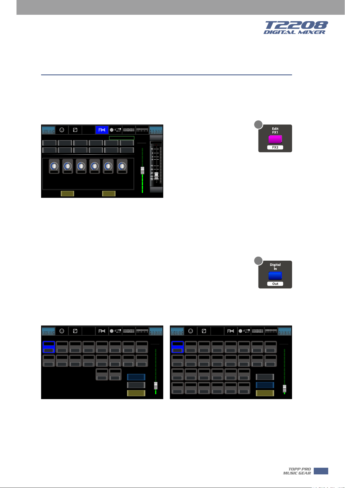
10. FX1-2 button
Press this button twice, it will switch between FX1 and FX2 function.
This page can show and editor the setting of internal effects. Each of the FX owns 12 program
effects. The window is as below.
For the detail operation, please refer to introduction in section 6.
Assign
Bank Select
Left
Effe ct Type:
Hall
Flanger
Param eters :
Attack
Gate
PEQ
Comp
DelayRev
Plate
Hi Damp
EQ
GEQ
Delay
StDelayRev
Efx Out
Channel
Room
Chorus
Decay
0 0 0 0 0 0
Load
FX1-2 Page
FX 1
FX 2
Dry Out Dry O ut
System
St Delay
Flanger Rev
Save
Routing
All Faders
Tremolo
ChorusRev
Bank Select
Long
DCA
Parameter
-10.5dB
Delay
Faders
Mute
-10. 5dB
CH08
Solo
CH08
Right
10
11. Digital In/Out button
Press this button twice, it will switch between Digital In and Digital Out function.
This button engages and disengages the digital channel when you have an optional input/output
module inserted.
5
˙Digital In
The button will illuminate to indicate that current channel has been selected as
11
digital input. The window is as below.
For the detail operation, please refer to introduction in section 6.
˙Digital Out
The button will illuminate to indicate that current channel has been selected as digital output.
The window is as below.
For the detail operation, please refer to introduction in section 6.
Assign
Bank Select
Left
-20.0dB
CH01
OFF
-20.0dB -20.0dB -20.0dB - 20.0dB -20.0dB - 20.0dB -20.0dB -20.0dB
CH09 CH10 CH16CH11 CH12 CH13 CH14 CH15
OFF
Gate
Channel
Comp
-20.0dB
-20.0dB
CH02
CH03
OFF OF F OFF OFF OF F OFF OFF
OFF OF F OFF OFF OF F OFF OFF
PEQ
EQ
-20.0dB
CH04
GEQ
FX 1
FX 2
-20.0dB
CH05
-20.0dB
CH17-18
OFF OF F
System
-20.0dB
CH19-20
Routing
-20.0dB
CH06
All Faders
-20.0dB
CH07
Digital Input
Digital Output
Channel Mapping
DCA
Digital In Page Digital Out Page
Long
-20.0dB
CH08
Faders
Bank Select
Parameter
CH01
-20.0dB
Right
Assign
Bank Select
Left
-25.0dB
CH01
OFF
0.0dB
CH09
OFF
0.0dB
AUX1
OFF
0.0dB 0.0dB 0.0dB0.0dB
AUX5
OFF OF F OFF OFF OF F OFF
Gate
Channel
Comp
0.0dB
0.0dB
CH02
CH03
OFF OF F OFF OFF OF F OFF OFF
0.0dB
0.0dB
CH10
CH11
OFF OF F OFF OFF OF F OFF OFF
0.0dB
0.0dB 0.0dB
AUX2
AUX3 AUX4
OFF OF F OFF OFF OF F
AUX6 AUX7 AUX8
FX 1
PEQ
EQ
GEQ
0.0dB
0.0dB
CH04
CH05
0.0dB
0.0dB
CH12
CH13
0.0dB
CH17-18
0.0dB 0.0dB
Main SOLO
All Faders
System
Routing
FX 2
0.0dB
CH06
0.0dB
CH14
0.0dB
CH19-20
DCA
0.0dB
CH07
0.0dB
CH15
Digital Input
Digital Output
Channel Mapping
Bank Select
Long
0.0dB
CH08
0.0dB
CH16
Faders
Parameter
CH01
-25.0dB
Right
When the button illuminated, please pay attention to which channel is Digital Input and which
channel is Digital Output during operation.
11
Control
5
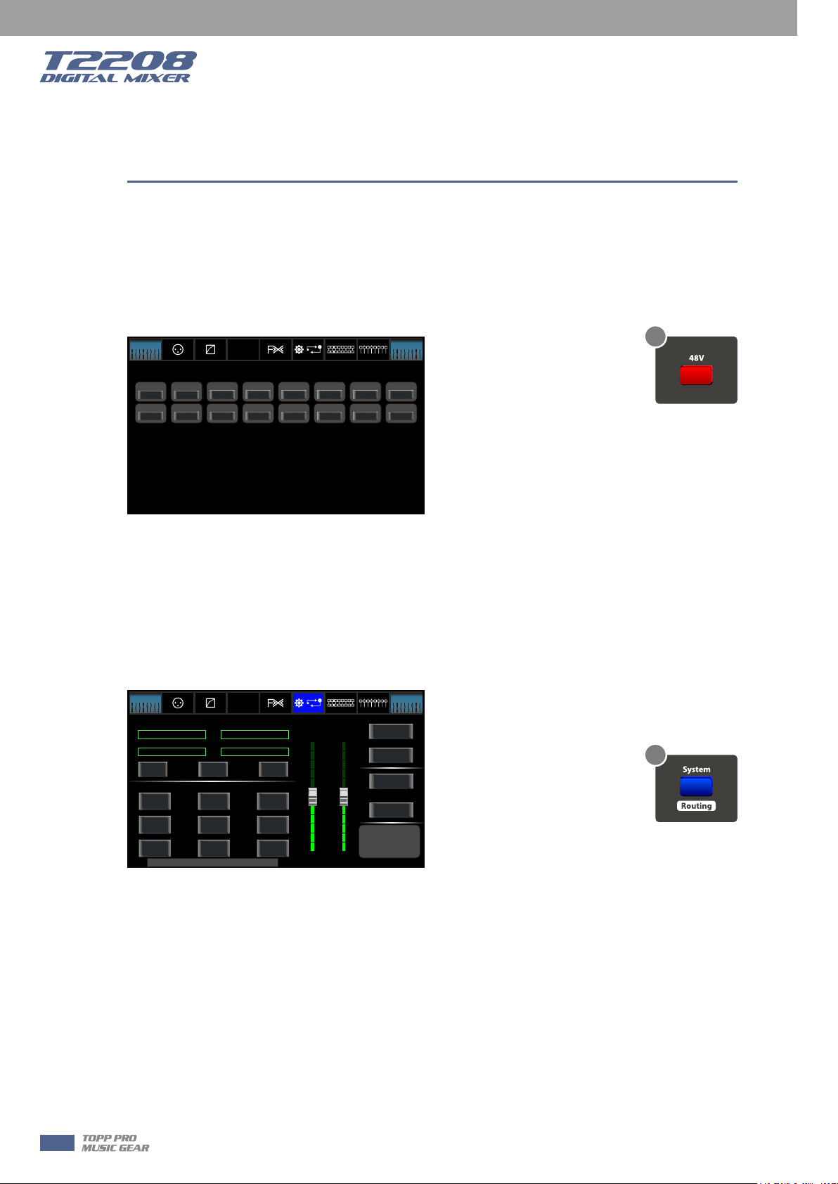
12. 48V Phantom button
Every microphone input equips with an individual phantom power which is controlled by the 48V
phantom power button. When you want to turn on phantom power of some channel, the screen
will show warning to ask you and make sure. It will illuminate when phantom power is activated.
Please notice that only the condenser microphone needs phantom power.
Note: Please do not supply phantom power to any device which do not need phantom power
otherwise the device and T2208 may be damaged.
Bank Select
Left
Assign
Channel
Gate
Comp
FX 1
PEQ
EQ
FX 2
GEQ
System
All Faders
Routing
DC48V
Ch01
OFF
OFF
OFF
OFF
OFF
Ch09 Ch16Ch10 Ch11 Ch12 Ch 13 Ch1 4 Ch15
OFF
OFF
OFF
OFF
OFF
OFF
OFF
48V Page
Bank Select
Long
DCA
OFF
OFF
Faders
Right
Ch08Ch02 Ch03 Ch0 4 Ch05 Ch06 Ch07
OFF
OFF
12
13. System/Routing button
Press this button twice, it will switch between System and Routing function.
˙System
Press this button to go to System page, as well as show and edit parameters of the system, as
below picture show.
For the detail operation, please refer to the introduction in section 6.
Assign
Bank Select
Left
Curr ent Sce ne
Default
FX1 FX2
Default
Load
Shor tcut To
Digital
48V
Fader
Calibration
Device Name: T2208
Gate
Channel
Comp
Copy
Routing
GEQ
Password
Setting
PEQ
EQ
GEQ
Sele cted Ch annel
Default
Default
FX 1
Save
Mete rs
DCA
Lock
Mixe r
FX 2
System
Routing
Brightness Adjus t
LCD
All Faders
Knob
Faders
DCA
Install Matrix
Default Setting
Default Page Setting
T1DSP_Firmw are_1_V1.0
T1DSP_Firmw are_2_V1.0
T3MCU_Firmw are_1_V1.0
T0MCU_Firmw are_2_V1.0
Lock Matrix
All Faders
Right
13
Bank Select
Long
System Page
˙Routing
Press this button again, user can select one or several channels in below windows to assign the
signal to corresponding outputs.
For the detail operation, please refer to introduction in section 6.
12
Control
Assign
Bank Select
Left
CH01 CH08CH02 CH03 C H04 C H05 CH0 6 CH0 7
OFF OFF OFF OFF OFF OFF OFF OFF
PRE
CH09 CH16CH10 CH11 C H12 C H13 C H14 CH 15
OFF OFF OFF OFF OFF
CH17 -18
OFF OFF OFF OFF OFF
PRE
Gate
Channel
PRE PRE
PRE
CH19 -20 FX1
PRE
Comp
PRE
PRE
FX 1
PEQ
EQ
PRE
PRE
PRE
FX 2
GEQ
PRE
PRE
FX2
USB
PRE
All Faders
System
Routing
PRE
OFF OFF OFF
PRE
PRE
PRE
Select
5
Bank Select
Long
DCA
PRE
PREPRE
POST
All:
Faders
Parameter
CH01
OFF
Right
Assign
Bank Select
Left
Ch01 Ch08Ch02 Ch03 C h04 Ch 05 Ch0 6 Ch0 7
OFF OFF OFF OFF OFF OFF OFF OFF
Ch09 Ch16Ch10 Ch11 Ch12 Ch 13 Ch1 4 Ch15
OFF OFF OFF OFF OFF
OFF OFF OFF OFF OFF
Channel
Gate
Comp
FX 1
PEQ
EQ
FX 2
GEQ
AUX1
System
Routing
USBCh17-18 Ch19-20 F X1 FX2
All Faders
DCA
OFF OFF OFF
Select
Long
Main
Faders
Bank Select
Right
- Page of routing input channels to AUX1
- Page of routing input channels to MAIN
(the same with AUX2-8)
Assign
Bank Select
Left
CH01 CH08CH02 CH03 C H04 C H05 CH0 6 CH0 7
OFF OFF OFF OFF OFF OFF OFF OFF
POST POST POST POST POS T POST POST POST
CH09 CH16CH10 CH11 C H12 C H13 C H14 CH 15
OFF OFF OFF OFF OFF
POST POST POST POST POS T POST POST POST
CH17 -18
OFF OFF OFF
POST POST POST
Channel
CH19 -20
Gate
Comp
FX 1
PEQ
EQ
FX 2
GEQ
USB
All Faders
System
Routing
DCA
OFF OFF OFF
All:
Select
Right
Faders
Parameter
CH01
OFF
PRE
FX1
Bank Select
Long
- Page of routing input channels to FX1
(the same with FX2)
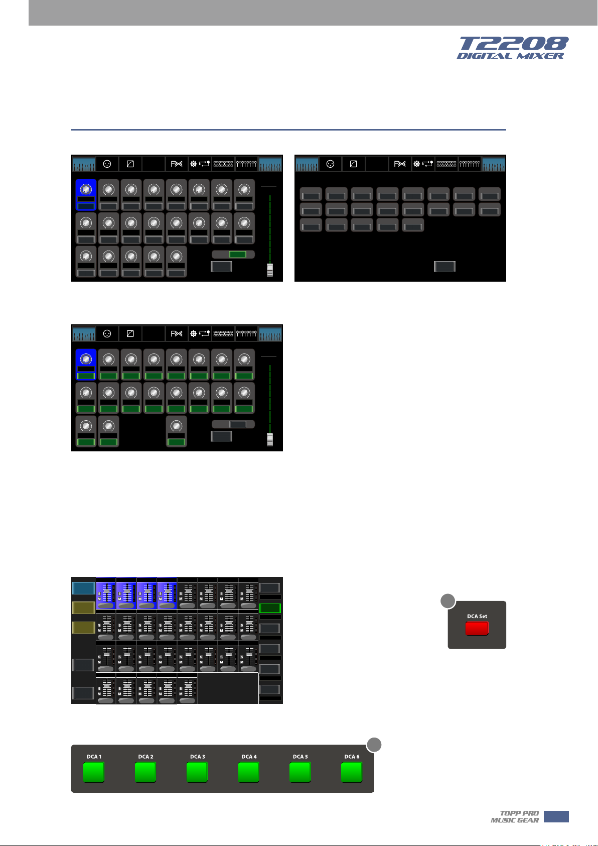
14. DCA button
Digital Control Audio(DCA) can realize group assignment. DCA volume control will always leave
the same ratio between the channel fader levels, independent of the volume control.
Press this button, it will flash until some channels have been selected, then press it again to save
the settings and turn off the button. The corresponding window is as below picture show.
For the detail operation, please refer to introduction in section 5.
Back
To
MIXER
Back
To
Previous
System
DCA Set
DCA Clear
00
0
0
0
CH17-18
-10dB
-10dB
-10dB
-10dB0-10dB0-10dB-10dB
0
Ch02 Ch03 Ch04Ch01
-10dB - 10dB -10dB
-10dB - 10dB -10dB
-10dB
-10dB
-10dB
0
000
Aux5Aux3 Aux4Aux2
-10dB
0
000
USBFX1 FX2Ch19-20
DCA Page
-10dB
-10dB
-10dB
Aux6 Aux7 Aux8Aux1
DCA A SSIGN W INDOW
Select DCA Group 1 to 6
Highlight/Assign Channels to DCA Group
Click "DCA Set" to Confirm!
-10dB
-10dB
-10dB
0000000
-10dB
DCA1
0000
Drums
Ch08Ch 07Ch06Ch05
DCA2
-10dB-10dB - 10dB -10dB
Back Vocals
0
DCA3
Ch16Ch 15Ch14Ch13Ch12Ch11Ch10Ch09
Aux & Fx
-10dB
DCA4
000
no name
DCA5
no name
DCA6
no name
14
15. DCA1-6 buttons
15
Press these buttons to select which channels you want to be assigned to the group.
13
Control
5
32
16
19
20
16. Assign to Main button
Press the input channel button, then press this button, can quickly assign the
input channel to main.
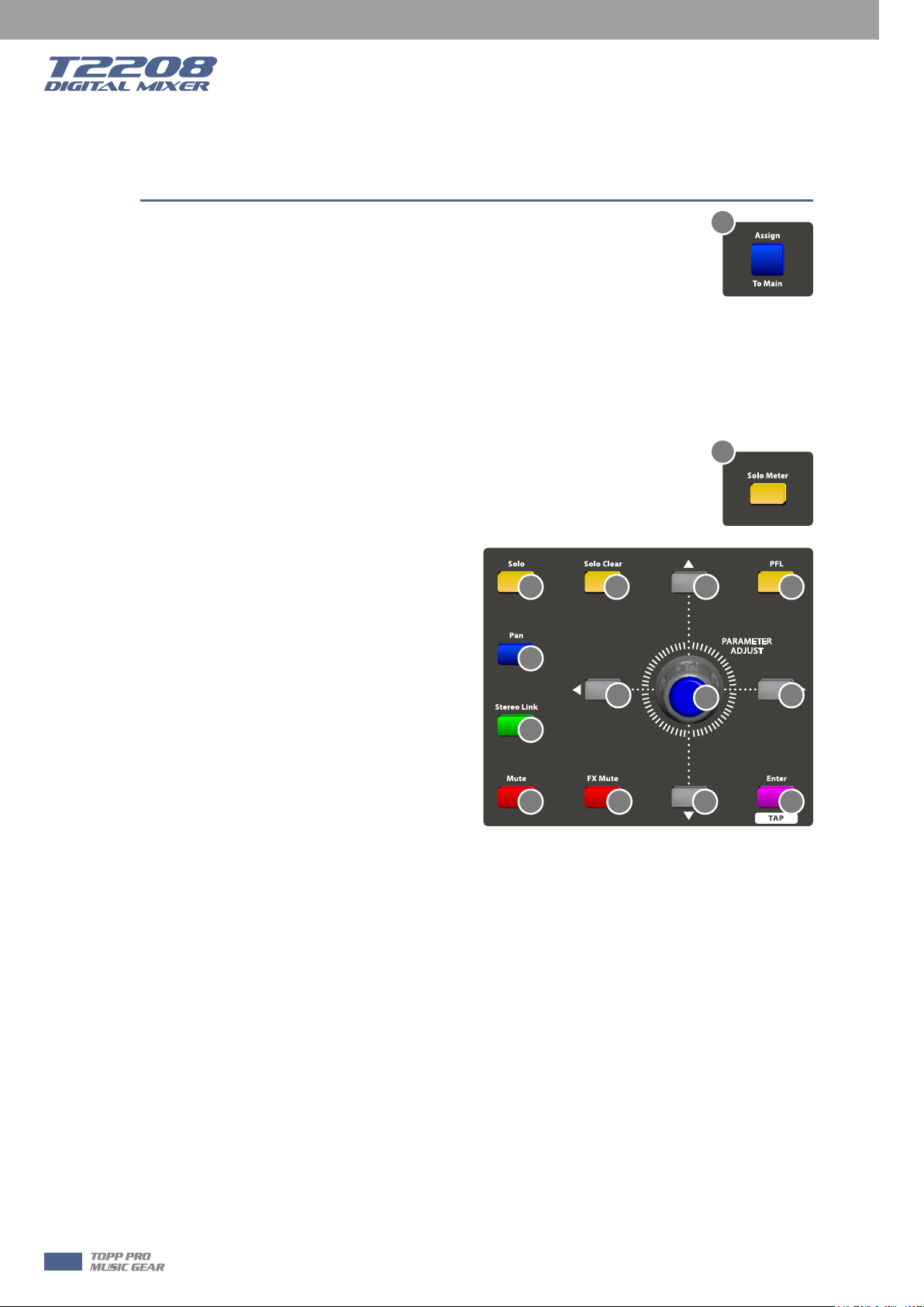
17. Solo button
Press this button will send its channels or buses to the control room outputs. It will illuminate as
has been pressed and enabled.
18. Solo clear button
Press this button to clear the solo function for all of the soloed buses or channels.
19. Solo Meter button
When the button is off, meters above it indicate input level of main, while
illuminated indicate input level of Solo.
20. PFL button
The default setting for the Solo bus is
After-Fader Listen (AFL); by pressing PFL,
Pre-Fader Listening is enabled. In either mode,
press Solo on any channel or bus to route that
channel to the Solo bus and has no effect on
the main.
17 18
21
21. Pan button
Press this button to select the Pan function,
then rotate Parameter Adjust encoder to
control signal level from left to right for the
selected input or output bus. If you have
adjusted a channel pan, please just touch 2
times on the screen and make it back to the
centre position.
The LCD display shows the setting in real time. If two channels have been linked as stereo pair,
the LCD display will automatically change to stereo pan.
22. Link button
Input channels, aux buses, can be linked as a stereo pair. It will illuminate if the stereo link button
has been pressed and enabled. The stereo pairs are predefined and cannot be changed. They are
as follows:
Channels 1 and 2 Channels 13 and 14
Channels 3 and 4 Channels 15 and 16
Channels 5 and 6 Aux 1 and Aux 2
Channels 7 and 8 Aux 3 and Aux 4
Channels 9 and 10 Aux 5 and Aux 6
Channels 11 and 12 Aux 7 and Aux 8
A stereo link can be enabled when either channel in the pair is selected by pressing the Link
button. When the Link button is illuminated which indicates the Stereo Link function enabled, all
DSP setting, solo status and main assignments are passed to the other channel in the pair.
22
23 24 32
32 32
34
33
14
Control
˙Link & DCA: After link, the channels can also be grouped to DCA as stereo channel, but not able
to cancel the link in DCA. On the contrary, if the channel has been grouped to DCA, it can not link
at all, but its paired channel can link.
For example, channel 5 is linked with channel 6, then both channel 5 and 6 can be grouped to
DCA. But if channel 5 has been grouped to DCA first, it can not link to channel 6, but channel 6
can link to channel 5.
˙Link & Routing: The two linked channels can route as stereo channel, while routed channels can
also link later.
Please note that this is a nondestructive passing, the other channel's previous setting will be
restored after the Link button is disengaged. For example, when Channel 6 has been selected,
then press Stereo Link button, all of Channel 6's setting will be copied onto Channel 5. The
Channel 5's own setting will restore after the Link button has been disengaged.
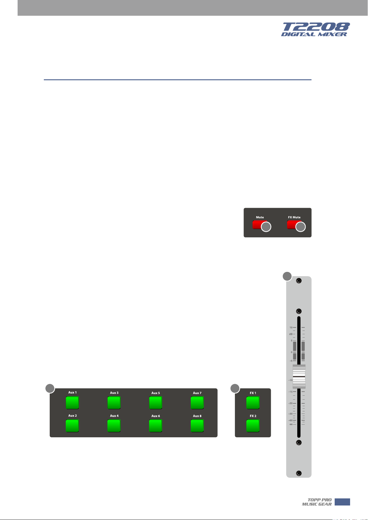
23. Mute button
Press this button will mute selected channel and all of its assigned
outputs. It will illuminate when the button has been pressed and
enabled.
24. FX Mute button
This button is for FX function, when press it, effects of FX1-2 will be mute synchronously, which
is similar to MUTE button.
23 24
5
25. Motor Fader
There is only one motor fader to control all digital Channel’s level, including 20 main
input channels, 1 USB in, 8 AUX outputs, FX1-2 and 1 Main output channel.
26. AUX1-8 select buttons
This button function is similar to input channel select buttons.
Press this button will route its channel to add DSP setting and assign its output. It will
illuminate as has been pressed and enabled. In DCA window, you can select group
channels by this button.
27. FX1-2 select buttons
This button function is also similar to input channel select buttons and AUX1-4 select
buttons. For the details, please refer to point 22 or 1.
26 27
25
Volume
15
Control
5
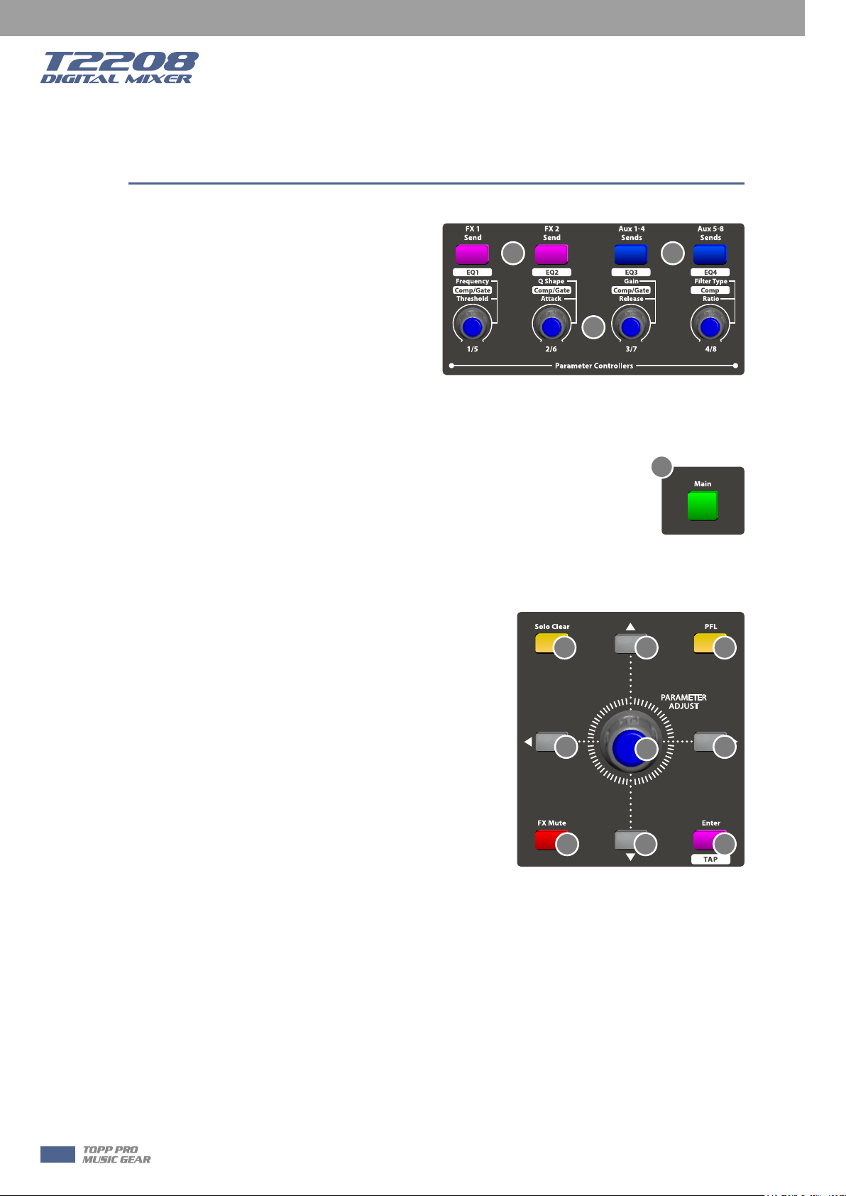
28. FX1/FX2 send
Press the input channel and then press this
button, can assign the channel to use FX1/FX2
effects. And the default level is mute, so you
should tune the knob below the button to take
effects.
29. Aux1-4/Aux5-8 sends
Press the input channel and then press this
button, can assign the channel to use
AUX1-4/5-8. And the default assigned level is mute, so you should tune the knob below the
button to take effects.
30. Main button
The selected channel can be assigned to Main Outputs by pressing the
corresponding button.
The main 20 inputs, USB In, and FX1-2 can be assigned to any or all of the Aux
Sends and the main outputs.
The 8 aux sends cannot be assigned to the main outputs.
31. AUX1-4/5-8 Output Level Control knobs
These knobs here control the output level for AUX1-4/5-8.
28 29
31
30
32. UP &Left & Down & Right button
These buttons move the cursor around the display page,
or select and delete parameters and options. Sometimes,
Up button function is the same as Left button, while
Down button function is the same as Right button. But in
GEQ, Up and Down adjust gain level, while Left and Right
adjust frequency.
As the function of this button will be a little bit different
in different function, please notice the notes that are
shown on the screen when operating.
33. Enter(TAP) button
This button can activate as two types of function.
˙Enter: Confirm the edited parameter values.
When there is a confirmation message jump out on the screen, press Enter button to answer
“yes”.
˙TAP: In the FX1 and FX2 page, it will switch to TAP function, you can use this button to enter a
delay time in tempo with the music being played.
As the function of this button will be a little bit different in different function, please notice the
notes that are shown on the screen when operating.
34. Parameter Adjust knob
This Encoder adjusts the parameter values of selected control that are shown on the LCD display.
Turning it clockwise increases the value and counterclockwise decreases the value.
As the function of this button will be a little bit different in different function, please notice the
notes that are shown on the screen when operating.
18
32 32
24 32
32
34
20
33
16

Control
35. Control Room knob
This knob controls the overall output level for control room.
36. HP1-2 knob
These knobs control the overall output level for headphones.
37. Main control knob
This knob here controls the overall output level for main channel.
5
35
36
36
30
37
5.2 Rear panel
38
40
50
45
41
39
46
47
42
48
49
38. Combo Jack
The Combo Jack Inputs integrates Mic and Line in together, insert in the middle hole to get Line
in function, while insert in the edge circle to achieve the Mic function.
The T2208 equips 16 microphone preamplifiers for use with all types of microphones.
The preamplifier has a Class A input buffer which followed by a dual-servo gain stage. This
arrangement will bring ultra-low noise and wide gain control which help to boost signals without
increasing unwanted background noise.
The line-level input is a 1/4-inch, balanced TRS connector. Each channel of the T2208 has a
line-level input. The microphone-preamp circuit will be bypassed if the Line-level Input has been
engaged.
Note: Please notice that there will be a momentary spike in the output when plugging in a
microphone or a line-level input device, or turning phantom power on or off. So it should be
better to mute or turn down the channel fader before changing connections or turning phantom
power on or off.
43 44
17

Control
5
39. Line inputs 17-20
The 17-20 Line Inputs are normally used as effects returns. A line bus can be used to send several
channels to an external effects processor and also can be used to return the processed signal to
the mixer. The input is balanced stereo. If a mono signal has to be returned to the mix, connect it
to the left input, then the right as well as the left side will get the signal.
40. Insert
Only channel 1-8 are equipped with insert function, while others are not.
The direct-insert point is an unbalanced 1/4-inch connector which can be used to connect
external processors. The insert's sending is after the channel's gain control and before the digital
bus. But the return goes to the digital bus directly. So if a de-esser has been inserted on the
vocalist's channel, the de-esser will get an unprocessed, amplified signal. The processed signal will
return to the T2208's digital bus to add DSP setting and sent through Aux and FX buses…
41. Aux Outputs1-8
These are balanced mono outputs for each auxiliary.
42. Headphones out HP1 and HP2
They are the headphone’s port for monitoring.
43. USB AUDIO in/Out
This port is for USB audio input and output. You can connect it to WINDOWS/MAC system
without any USB driver.
HP1
HP2
44. CTRL Out
These are the balanced control-room outputs. The level is controlled by the knob in the Control
Room on the top panel.
45. Main Output
The T2208 features both XLR and TRS main outputs. These outputs are parallel to each other.
46. USB connect port
This port is for remote control or firmware update.
47. Ethernet connect port
This port is for Ethernet control or firmware update.
NOTE: You can choose T-WIFI module to change Ethernet/USB module to WIFI/USB module.
48. AC Input
The provided power cable can be plugged in.
49. Power Switch
Power switch ON or OFF
50. Optional module
Select our optional module that you want for extra function.
(1) T-DANTE module : DANTE networking module.
(2) T32USB-EXP module:32 I/O Multi-track recording module.
18
Please contact with your distributor to get more information about the optional modules.

DSP Control
The DSP control part is the most important part of T2208. In this part you can adjust Gate,
Compressor, EQ, polarity, panning, delay, link, routing, etc. for the selected channel.
Here is the table lists each input/output channel that with DSP function.
Bus
Inputs
(CH1-16)
Inputs
(CH17-20)
Aux
sends1-8
FX1-2
MAIN Out
Gate Compressor EQ Polarity Pan Delay Link Output Assignment
√
√
×
×
√ √ √ √ √ √
√ √ √ √ √ ×
√ √ √ × √ √
√
√ √ √ √ √
MAIN, AuX Sends
1-8, FX 1-2
MAIN, AuX Sends
1-8, FX 1-2
MAIN
× √ √ √ × √ ×
6.1 Mixer interface
Once you turn on the T2208 switch, the Mixer interface will come to your eyes at first if you have
preseted, now let’s see what you can get in this interface.
6
-10dB
DCA
Mute Mute
-10. 5d B
CH01
Solo
CH01
-10dB
0
0
Ch01
-10dB
-10dB
0
Aux1
-10dB
0 0
0
Touch a channel, for example, CH01, the background and corresponding CH1 button
will illuminate synchronously, you can control the output signal level by Parameter
-10dB
Ch02 Ch08Ch0 7Ch06Ch05Ch04Ch03
-10dB
-10dB -10dB -10dB
-10dB -10dB -10dB
Ch19-2 0
-10dB
-10dB
Ch11Ch10Ch09
000
Aux3
000
FX1 FX2
-10dB
-10dB
Ch12 Ch15Ch14Ch13
Aux4Aux2
-10dB
-10dB
-10dB
Aux5 Aux6
-10dB
USBCh17-1 8
-10dB
-10dB
-10dB
-10dB
-10dB
0000000
-10dB
Aux7 Aux8
DCA 1 DCA 2
DCA 3 DCA 4
DCA 5 DCA 6
-10dB
0000000
-10dB
0
Ch16
-10dB
0000
Adjust knob.(Please notice pan button should not be lit, or the Parameter Adjust knob
controls the pan)
Ch01
Long Fader
-10. 5d B
-10. 5d B
Main
Main
Name
Name
19

DSP Control
6
DCA
Mute
-10. 5d B
CH01
Solo
CH01
-10. 5d B
Meter beside the fader indicates the input signal level activity .This long fader can
control level of all input and output channels in this screen, but for one selected
channel at one time, all its control will change synchronized with the selected
channel.
-10. 5d B
Meter beside the fader indicates signal activity.
The number indicates current channel level.
The pan icon shows real pan of selected channel audio signal, press
Pan button on the panel and rotate Parameter Adjust knob to adjust it.
Solo
Mute
CH01
Touch the icon to monitor selected channel audio signal, it will
illuminate synchronized with Solo button on the panel.
Touch the icon to silence selected channel audio signal, it will
illuminate synchronized with Mute button on the panel.
This letter shows the real current channel. You can also rename the
channel. Touch it and hold for a while, a virtual key will come into your
vision, as below picture show. Now
please tap the keyboard and give a
new name to this channel as you like.
Q W E R T Y U I O P
A S D F G H J K L
Z X C V
123
123
.
.
?
?
B
N
!
M
,
Enter
?
.
123
123
.
.
?
?
DCA
Long Fader
Touch them to enter the
corresponding interface as
you like. You can also select them by buttons on
Slide the fader, you can
increase or decrease
corresponding channel’s
CH01
DCA 1 DCA 2
level.
This shortcut give you a convenience to operation channels that grouped
the panel, they appear here just to provide an
extra entrance for you. For their detail functions,
please refer to the corresponding introduce
section.
by DCA1-6. For example, when you touch DCA2, its background will
DCA 3 DCA 4
DCA 5 DCA 6
illuminate synchronized with DCA2 button on the panel. All channels
you have grouped to DCA2 will also illuminate, now you can adjust
motor fader and Parameter Adjust knob on panel or long fader on the
screen to adjust level.
But if you didn’t group DCA2 before, then you touch DCA2 icon here, a hint will prompt says “The
DCA group is not defined!”
For their detail functions, please refer to the DCA introduce section 6.10.
20

DSP Control
6.2 Long Faders interface
Bank Select
Left
-10.5d B -1 0. 5d B -1 0. 5d B -1 0. 5dB -10.5d B-10.5d B-10.5d B-10.5d B
CH01 CH0 2 CH 03 CH 04 CH0 5 CH 06 CH0 7
CH01 CH0 2 CH 03 CH 04 CH0 5 CH 06 CH0 7 CH08
Assign
Channel
MuteMute
SoloSolo So lo Solo Solo Solo Solo Sol o
Gate
PEQ
EQ
Comp
Mute Mute Mute Mut e Mu te
GEQ
FX 1
FX 2
System
Routing
All Faders
DCA
Long
-10.5d B
Faders
Mute
CH08
Bank Select
Right
Mute
Main
Main
6
Bank Select
Left
Mute
-10.5d B
CH01
Solo
CH01
Bank Select
Touch this icon to switch channels and enter corresponding Long Faders
Right
page, in which you can adjust channels’ basic function like pan, solo,
mute, level and rename the channel, etc.
Functions on this icon (like mute, level number, pan, long fader, solo and channel
name) are the same with that in Mixer interface.
21

DSP Control
6
6.3 Assign interface
The 20 main inputs and internal FX returns can be assigned to any or all of the outputs, Aux
sends and main outputs.
In this page, Aux 1-4 and AUX5-8 can switch to each other by touching a switch icon in System
page.
First, let’s see the Aux1-4 mode as below picture show.
Bank Select
Left
DCA Assign
DCA 1 DCA 2 DCA 3
DCA 4 DCA 5 DCA 6
Assign
Sends
-10. 5d B -10. 5d B -10. 5d B -10. 5d B -10. 5d B -10. 5d B
48V
Assign
Channel
PRE PRE PRE PRE
Link
Gate
PEQ
EQ
Comp
Left
Main
AUX2 AUX4AUX1
Phase
AUX3
AUX1-4
Select
Channel
GEQ
Pan
FX 1
System
FX 2
AUX5-8
FX1
POST POST
Load
Routing
Copy
Channel
All Faders
Right
FX2
Save
DCA
Long
Faders
Parameter
Aux 1
-10.5dB
Bank Select
Right
Mute
-10. 5d B
CH08
Solo
CH08
Main
AUX1-4
AUX5-8
Touch Main AUX1-4 on the LCD screen or
corresponding button on the panel to assign input
channel audio to these channels or buses. They will illuminate synchronizing with buttons in
Assign area on the panel after pressed. To adjust output level of the channel audio, you can rotate
Parameter Adjust knob or corresponding Main or AUX1-4 knobs on the right corner of the panel.
AUX2 AUX4AUX1
-10. 5d B -10. 5d B -10. 5d B -10. 5d B -10. 5d B -10. 5d B
PRE PRE PRE PRE POST POST
AUX3
FX1
FX2
Touch AUX1-4 and FX1-2 on the LCD screen or press corresponding button on the panel to assign
input channel audio to these channels or buses. To adjust output level of the channel audio, you
can rotate Parameter Adjust knob on the panel.
Touch PRE on the screen, it will switch to POST, the AUX & FX send will derive its signals from all
channels post-fader. If the icon has not been pressed and not illuminate, by default, the AUX &
FX Send will derive its signal from all channels pre-fader and all unaffected by the sending
channel’s fader position.
In a word, touch PRE and switch it to POST, then you can adjust its level by sliding fader.
Otherwise, the fader wouldn’t function on level adjustment.
22

DSP Control
Mute
-10. 5d B
Slide the fader to change selected input channel audio.
The fader function is the same with Fader on the panel,
which can control input signal’s level, they will change
Parameter
Aux 1
-10.5dB
synchronously.
Meter beside it indicates the signal level activity.
Pan above fader indicates value of pan setting.
Solo can monitor selected channel audio.
Mute can silence selected channel audio.
Long press CH01 can rename the selected channel.
Adjust this parameter to change selected output
channel audio. This fader function is the same
with Parameter Adjust knob, they will change
synchronously.
Right
Touch pan left or right to change signal’s
Left
CH08
Solo
CH08
Pan
balance effect, it can be adjusted by
Parameter Adjust knob on the panel when
pan button is on.
If you have adjusted a channel pan, please just touch 2 times on the screen and make it back to
the centre position.
For the details please refer to the Pan introduction in section 5.
6
48V
Link
Select
Channel
Phase
Load
Copy
Channel
Save
Touch anyone of these controls to enter corresponding
page.
Touch it, the background and Link button will illuminate synchronously, and current
channel will link to its default paired-channel, the button will illuminate then.
Touch Select icon here, all input channels will display to you. Please follow the
indication on the LCD screen to operate.
For different input channels, the function and output assignments are different,
please notice indication on the screen.
23

DSP Control
6
When switch to AUX 5-8, the corresponding page is as below picture show, this function enable
output assignments to be more.
Bank Select
Left
DCA Assign
DCA 1 DCA 2 DCA 3
DCA 4 DCA 5 DCA 6
Assign
Sends
-10. 5d B -10. 5d B -10. 5d B -10. 5d B -10. 5d B -10. 5d B
48V
Assign
Channel
PRE PRE PRE PRE
Link
Gate
PEQ
EQ
Comp
Left
Main
AUX6 AUX8AUX5
Phase
AUX1-4 AUX5-8
AUX7
Select
Channel
GEQ
Pan
FX 1
System
FX 2
FX1
POST POST
Load
Routing
Copy
Channel
All Faders
Right
FX2
Save
DCA
Long
Faders
Parameter
Aux 1
-10.5dB
Bank Select
Right
Mute
-10. 5d B
CH08
Solo
CH08
AUX6 AUX8AUX5
-10. 5d B -10. 5d B -10. 5d B -10. 5d B -10. 5d B -10. 5d B
PRE PRE PRE PRE POST POST
AUX7
FX1
FX2
Touch AUX5-8 and FX1-2 on the LCD screen to assign input channel audio to these channels or
buses. To adjust output level of the channel audio, you can rotate Parameter Adjust knob on the
panel.
For other icon functions in this page, they are the same with those in AUX1-4 mode.
24

DSP Control
6.4 Channel interface
INV.
Delay
Link
Main
Assign
Channel
Left
Gate
Threshold Threshold
0.0d B 0.0d B
ON
Load
Bank Select
Left
Polarity
Delay Time
0.0m S
Gate
Comp
Copy
Channel
PEQ
EQ
ON
FX 1
GEQ
Pan
EQ
Rock Drums
Save
FX 2
Flat EQ
System
Routing
Select
Channel
All Faders
Right
Compressor
ON
DCA
Long
Parameter
Aux 1
-10.5dB
Faders
Bank Select
Right
Mute
-10. 5d B
CH08
Solo
CH08
6
INV.
Touch it in Polarity to invert the phase of the selected channel's signal (to alter the
phase by 180°). If the phase reverse is active the button will illuminate. The LCD
display shows the phase reverse setting in real time. The Polarity control can be used to correct
audio signals which are out of phase as well as to cancel/reinforce each other.
Delay
Touch it in Delay Time can engage and disengage the delay for the selected channel.
It will illuminate to indicate that the delay has been pressed and enabled. The LCD
display shows the delay time in real time. It can be set 300ms at 48K Hz. Please notice that only
if the Delay button has been enabled can its parameter be adjusted.
0.0m S
When Delay icon is engaged, touch it in Delay Time and rotate the Parameter Adjust
knob can control the selected channel’s delay time.
Link
Main
Touch it, the function is the same as Link button.
Touch this control, it will illuminate as well as the button, signal from a selected
channel can be assigned to Main channel, for the details please refer to Assign
introduction in section 6.3.
Gate
Touch the switch ON to enable Gate function, then rotate Parameter Adjust knob or
slide long fader on the right LCD screen to adjust value of Threshold, which will show
in the middle box. During adjustment, corresponding figure change will show in the
Gate grid.
In this area, you can touch the grid area to enter Gate page, for the detail of Gate
Threshold
0.0dB
function, please refer to the Gate introduction in section 6.5.
ON
25

DSP Control
6
ON
Compressor
Threshold
0.0d B
ON
EQ
Touch the switch ON to enable EQ function, it will illuminate
and synchronize with ON/OFF control in EQ page. Please set
values in EQ page because it is not adjustable here. This page
can only show the values. You can also load a preset, please
refer to load introduction section for the detail operation, the
loaded state will show in the middle box.
Rock Drums
Flat EQ
Touch Flat EQ to eliminate EQ settings and restore it to default.
In this area, you can touch the grid area to enter EQ page, for
the detail of EQ function, please refer to the EQ introduction in
section 6.7.
Touch the switch to enable Compressor function, then rotate Parameter Adjust
knob or slide long fader on the right LCD screen to adjust value of Threshold, which
will show in the middle box. During adjustment, corresponding figure change will
show in the Compressor grid.
In this area, you can touch the grid area to enter COMP page, for the detail of
COMP function, please refer to the COMP introduction in section 6.6.
Load
Select
Channel
Copy
Channel
It is the same with that in Assign interface in section 6.3.
Note: you can also rename the selected channel by long pressing CHXX.
6.5 Gate interface
Bank Select
Left
Assign
Channel
Gate
Level LIMIT
(dB)
CLIP
16
10
12
7
7
4
3
2
-1
0
-5
-2
-10
-4
-14
-7
-18
-10
-22
-20
-26
-30
-30
Load
Gate
Copy
Channel
Save
Comp
Default
Touch anyone of these controls to enter corresponding page.
PEQ
FX 1
System
All Faders
Long
Bank Select
EQ
Save
GEQ
ON
(dB )
4
8
13
17
21
25
30
34
38
42
46
50
Select
Channel
FX 2
Routing
DCA
Thresh old
0.0dB
Attack
50mS
Releas e
100mS
Faders
Parameter
Aux 1
-10.5dB
Mute
-10. 5d B
CH08
Solo
CH08
Right
26

DSP Control
ON
Touch the switch in this window, you can engage and disengage the Gate for the
selected channel. It will illuminate to indicate that the Gate has been touched and
enabled. The LCD display shows the Gate setting in real time. Its parameters can change by
adjusting Threshold, Attack & Release control directly and use the Parameter Adjust knob to set
the value.
Please notice that only if the Gate control has been enabled can its parameters be adjusted.
The bar has 3 colors here, which indicate 3 status.
˙Grey- the switch is OFF.
˙Green- the switch is ON, there is signal input and the value is below threshold level, which
means it enables the gate function.
˙Red- the switch is ON, but gate function not enable.
Thresh old
0.0dB
Attack
50mS
Releas e
Touch it to set the level at which the gate will open. It can be set from 0 to -84 dB.
Touch it to set the time for the gate to change from closed to open, much like a
fade-in. It can be set from 0.5 to 200 ms.
Touch it to set the amount of time for the gate to go from open to fully close.
It can be set from 0.01 to 1 second.
100mS
Note: A fast release abruptly cuts off the sound once it has fallen below the
threshold, A slower release smoothly changes from open to closed, much like a slow fade out.
If the release time is too short a click can be heard when the gate re-opens.
6
Level LIMIT
(dB)
CLIP
10
7
4
2
0
-2
-4
-7
-10
-20
-30
Load
Select
Channel
16
12
7
3
-1
-5
-10
-14
-18
-22
-26
-30
Copy
Channel
Save
It is the same with that in Assign interface in section 6.3.
Note: you can also rename the selected channel by long pressing CHXX.
(dB )
13
17
21
25
30
34
38
42
46
50
Touch anyone of these controls to enter corresponding page.
4
8
The Gate grid shows level setting of threshold in
real time. Meter on the left indicates the input
signal’s level activity.
27

DSP Control
6
6.6 COMP interface
Bank Select
Left
Assign
Channel
Comp
Level LIMIT
(dB)
CLIP
10
-10
-20
-30
7
4
2
0
-2
-4
-7
16
12
7
3
-1
-5
-10
-14
-18
-22
-26
-30
Load
Gate
Copy
Channel
Comp
Default
PEQ
EQ
Save
GEQ
FX 1
(dB )
ON
4
8
13
17
21
25
30
34
38
42
46
50
Select
Channel
FX 2
System
Routing
All Faders
Thresh old
0.0dB
Attack
50mS
Releas e
100mS
Comp Ratio
1:1
Comp Gain
0.0dB
DCA
Long
Parameter
Aux 1
-10.5dB
Faders
Bank Select
Right
Mute
-10. 5d B
CH08
Solo
CH08
ON
Touch the switch in this window, you can engage and disengage the Compressor for
the selected channel. It will illuminate to indicate that the compressor has been
pressed and enabled. The LCD display shows the compressor setting in real time. Its parameters
can change by rotating the Parameter Adjust to set the value of Gain, Threshold, Attack, Release
& Ratio control directly or using up & left & down & right key to choose the function that you
want to modify. Please notice that only if the Compressor button has been enabled can its
parameters be adjusted.
The bar has 3 colors here, which indicate 3 status.
˙Grey- the switch is OFF.
˙Green- the switch is ON, there is signal input and under compressing, which means it enables
the compressor function.
˙Red- the switch is ON, but compressor function not enable.
Comp Gain
Touch it to set the gain of the compressor for the selected channel or bus. Generally,
when compressing signal, the decreasing of gain will cause whole level
0.0dB
attenuation. This Gain control can recover the lost level and re-adjust volume that
compressed before. The Gain can be set from 0 dB (no gain adjusted) to +24 dB.
Thresh old
Touch it to set the compressor threshold for the selected channel. If the amplitude
of an audio signal exceeds a certain threshold, the compressor will reduce the level
0.0dB
of this signal. The threshold can be set from -30 to 20 dB.
28
Attack
50mS
Touch it to set the compressor's attack setting for the selected channel. The attack
setting is the period when the compressor is decreasing gain to reach the level that
is determined by the ratio. You can set the attack from 10 to 150 milliseconds.

DSP Control
Releas e
Touch it to set the compressor for the selected channel. Release sets the length of
time the compressor takes to return to its normal gain once the signal level drops
100mS
Comp Ratio
below the threshold. Release can be set from 10 to 1,000 milliseconds.
Touch it to set the compression ratio for the selected channel. The ratio determines
the amount of gain reduction. For example, a ratio of 4:1 means that if input level
1:1
is 4 dB over the threshold, the output signal level will be 1 dB over the threshold.
The ratio can be set from 10:1 to 1:1 until limit.
Level LIMIT
(dB)
CLIP
16
10
12
7
7
4
3
2
-1
0
-5
-2
-10
-4
-14
-7
-18
-10
-22
-20
-26
-30
-30
Load
Copy
Channel
Save
(dB )
13
17
21
25
30
34
38
42
46
50
Touch anyone of these controls to enter corresponding page.
6
The compressor grid shows level setting of
4
8
threshold in real time.
Meter on the left indicates the input signal’s
level activity.
Meter on the right indicates degree of
compressor.
Select
Channel
It is the same with that in Assign interface in section 6.3.
Note: you can also rename the selected channel by long pressing CHXX.
6.7 PEQ interface
Bank Select
Left
+24
+18
+12
+6
0 dB
-6
-12
-18
-24
20Hz 50 100 200 500 1K 2K 5K 10K 20K
Frequency
200H z
Type
BW2 4
Frequency
200H z
Type
BW24
Assign
Channel
HPF
EQ1
EQ2
LPF
EQ3
EQ4
Gate
Frequency
200H z
1.0K Hz
5.0K Hz
10.0 KHz
PEQ
EQ
Comp
Q Gain Type
3.0
3.0
3.0
3.0
GEQ
0.0d B
0.0d B
0.0d B
0.0d B
FX 1
System
FX 2
Routing
Select
Channel
OFF
Flat EQ
All Faders
Frequency
1.0KHz
Q
3.0
Gain
-2.0dB
Load
Copy
Channel
Save
DCA
Long
Parameter
Aux 1
-10.5dB
Faders
Bank Select
Right
Mute
-10. 5d B
CH08
Solo
CH08
29

DSP Control
6
OFF
Touch the switch to engage or disengage the equalizer for the selected channel. It will
illuminate to indicate that the equalizer has been touched and enabled. The LCD display
shows the EQ setting in real time. Its parameters can adjust by sliding the curve on the screen
directly or using up & left & down & right key to choose the function that you want to modify and
use the Parameter Adjust knob to set the value.
Please notice that only if the EQ button has been enabled can its parameters be adjusted. The
equalizer is available for all input and output buses.
Flat EQ
Touch it, a dialog box saying “ Are you sure to flat the EQ? ” will prompt to check with
you, if you click “yes”, all the setting values in this page will restore to default, while
choose “no” can keep your settings.
Frequency
Touch it to set the center frequency of the equalizer's Low/Low-mid/High-mid/ High
band separately. The center frequency is the middle of the pass-band between the lower
1.0KHz
and upper cutoff frequencies which define the limits of the band. The center frequency
can be set from 20Hz to 20K Hz.
Touch it to set the Q for the Low/Low-mid/High-mid/High band separately. The Q is the
Q
ratio of the center frequency to the bandwidth. If the center frequency is constant, the
3.0
bandwidth is inversely proportional to the Q, which means that if you raise the Q, the
bandwidth will be narrowed. It can be adjusted from 0.4 to 24.
Gain
-2.0dB
Frequency
200H z
Type
BW2 4
Frequency
200H z
Type
BW24
Frequency
EQ1
EQ2
EQ3
EQ4
Touch it to set the gain cut or boost at the center frequency for the
Low/Low-mid/High-mid/High band separately. It can be set from -24 to +24 dB.
This is a high-pass filter. It can pass higher frequencies. When set to its lowest
HPF
position, the filter is off.
Type indicates the filter’s type that you selected, different type means different
shape and different filter frequency range.
This is a low-pass filter. It can pass lower frequencies. When set to its highest
LPF
position, the filter is off.
Type indicates the filter’s type that you selected, different type means different
shape and different filter frequency range.
Touch EQ1 to set its Frequency, Q and Gain
parameters separately, touch Type to change the
filter to high-pass, low-pass or band-pass filter, the
200H z
1.0K Hz
Q Gain Type
3.0
3.0
0.0d B
0.0d B
same as EQ2, EQ3 and EQ4. You can see the
5.0K Hz
10.0 KHz
3.0
3.0
0.0d B
0.0d B
waveform on the screen.
Note: you can also rename the selected channel by
long pressing CHXX.
30

DSP Control
6.8 GEQ interface
Bank Select
Left
+24
+18
+12
+6
0(dB )
-6
-12
-18
-24
Frequency
Assign
Gate
PEQ
EQ
Channel
1 2 3 4 5 6 7 8 9 1 0 11 12 13 14 15 16 17
25 40 63 100 160 250 400 630
20
31.5 50 80 125 200 315 500 800 1.25K 12.5K2K
Gain
200H z 0.0dB
Load
Comp
GEQ
Flat EQ
Save
ON
FX 1
FX 2
Select
Channel
System
Routing
18 19 20 21 22 23 24 25 26 27 28 29 30 31
1K 1.6K 2.5K 4K 6.3K 10K 16K
Defa ul t
All Faders
Long
DCA
3.15K 5K 8K
Left Right
Faders
Main
Bank Select
Up
Down
6
Right
20K
The T2208 features MAIN Stereo, AUX Mono, 31-band, 1/3 octave graphic EQs. The 31 bands
range from 20Hz to 20 KHz. There is 1 MAIN Stereo GEQ, 8 AUX Mono GEQs in 24-bit/48 kHz
sample rate.
1 2 3 4 5 6 7 8 9 1 0 11 12 13 14 15 16 17
+24
+18
+12
+6
0(dB )
-6
-12
-18
-24
25 40 63 100 160 250 400 630
20
31.5 50 80 125 200 315 500 800 1.25K 12.5K2K
18 19 20 21 22 23 24 25 26 27 28 29 30 31
1K 1.6K 2.5K 4K 6.3K 10K 16K
3.15K 5K 8K
20K
In this screen, you can adjust gain at every specific frequency. The EQ number, Frequency and
Gain value which you are adjusting will be shown on the LCD below the graphic curve. Please
follow the instruction that is shown on the LCD display to adjust the value.
Flat EQ
The Flat EQ button can help you set the whole 31 bands to be default setting.
Frequency
200H z 0.0dB
Gain
The box can show the frequency and gain that you are adjusting.
Up
Left Right
Down
Touch Left or Right to select frequency, while touch Up or Down to
fine adjust gain of selected frequency.
31

DSP Control
6
Load
Save
Touch Load, Save to realize corresponding function.
Select
Channel
Touch this control in this area to enter page of corresponding channel.
ON
Defa ul t
Touch ON/OFF switch, it will illuminate and enable the GEQ
function.
Compare with ON in other page, the different is that even you don’t turn on it, the GEQ
parameter is adjustable, but won’t function.
Text Default in the box shows preset of GEQ. You can change it by loading another parameter
setting.
The GEQ settings can be saved as preset for future use by pressing the Save button and flowing
instruction that is shown on the LCD display. Please notice that the assign state will not be saved
when one GEQ setting is saved as preset (assign state could be saved in scene option) . The preset
can be recalled by pressing the Load button and deleted by pressing the Flat EQ button after it
has been chosen. Please notice the instruction that is shown on the LCD display. Please take
section of DSP Load, Save, Copy as reference.
6.9 FX1-2 interface
The setting values of FX1-2 can be saved as preset for future use by simply touching the Save
button and following the instruction that is shown on the LCD display.
Bank Select
Left
Effe ct Typ e:
Hall
Flanger
Par am eters :
Attack
Hall
Assign
Gate
PEQ
FX 1
System
EQ
Channel
Room
Chorus
Decay
0 0 0 0 0 0
Load
Room
Comp
Plate
DelayRev
Hi Damp
Plate
GEQ
Delay
StDelayRev
Efx Out
Delay
FX 2
Dry Out Dry Out
Routing
St Delay
Flanger Rev
Save
St Delay
All Faders
Tremolo
ChorusRev
Tremolo
DCA
Long
Parameter
Delay
-10.5dB
Faders
Bank Select
Right
Mute
-10.5d B
CH08
Solo
CH08
32
Flanger
Chorus
DelayRev
StDelayRev
Flanger Rev
ChorusRev
Touch anyone of these controls to adjust parameter of the effects by rotating Parameter Adjust
knob or slide fader on the right of LCD screen.

DSP Control
Mute
Touch this control to mute current FX effect.
The T2208 includes 12 kinds of adjustable effects which can help to realize the effect that you
want to show your audience.
No. Preset Description Parameter
1 Hall
2 Room
3 Plate
4 Delay
5 Stdelay
6 Tremolo
7 Flanger
Simulate an acoustic space of the
sound
Simulate a studio room with many
early reflections
Simulate the transducer's sound like
classic bright vocal plate
Reproduce the sound input on the
output after a lapse of time
Recreate the input sound on the
stereo output with different time
Simulate the sound effect by
repeating the same note or different
notes alternately and quickly
Simulate to play with another person
carrying out the same notes on the
same instrument
Pre Delay; Decay; Room Size; Hi Damp;
Efx Out; Dry out
Pre Delay; Decay; Room Size; Hi Damp;
Efx Out; Dry Out
Pre Delay; Decay; Room Size; Hi Damp;
Efx Out; Dry out
Time; Decay; Hi Damp; Efx Out; Dry
Out
L Time; R time; L Decay; R Decay; Hi
Damp; Efx Out; Dry Out
Feed Back; Depth; ModFreq; Efx Out;
Dry Out
ModFreq; Efx Out; Dry Out
6
8 Chorus
9 DelayRev
10 StDelayRev
11 FlangerRev
12 ChorusRev
Recreate the illusion of more than one
instrument from a single instrument
sound
Delay with room effect
Stereo Delay with room effect
Stereo chorus and large room reverb
Simulate the sound effect achieved by
rotating horn speakers and a bass
cylinder
Feed Back; Depth; ModFreq; Efx Out;
Dry Out
Pre Delay; Rev Decay; Room Size; Rev
Hi; Rev Out; Echo Time; Echo Hi; Echo
F.B; Echo out; Dry Out
Pre Delay; Rev Decay; Room Size; Rev
Hi; Rev Out; L Time; R Time; L Decay; R
Decay; Echo Hi; Echo Out; Dry Out
Pre Delay; Rev Decay; Room Size; Rev
Hi; Rev Out; ModF.B; ModDepth;
ModFreq; Mod Out; Dry Out
Pre Delay; Rev Decay; Room Size; Rev
Hi; Rev Out; ModF.B; ModDepth;
ModFreq; ModOut; Dry Out
33

DSP Control
6
6.10 Digital Input interface
Only channel 1-16 are given digital input. You can select which channels input from option
module, and which channels input from analog.
The screen will give clues if no digital card inserted in, and the Digital in function can not enable
either.
Bank Select
Left
-20.0dB
CH01
OFF
-20.0dB -20.0dB -20.0dB -20.0dB -20.0dB -20.0dB -20.0dB -20.0dB
CH09 CH10 CH16CH11 CH12 CH13 CH14 CH15
OFF
Assign
Gate
PEQ
EQ
Channel
-20.0dB
CH02
OFF OFF OFF OFF OFF OFF OFF
OFF OFF OFF OFF OFF OFF OFF
Comp
-20.0dB
CH03
-20.0dB
CH04
GEQ
FX 1
FX 2
-20.0dB
CH05
-20.0dB
CH17-18
OFF OFF
System
Routing
-20.0dB
CH06
-20.0dB
CH19-20
All Faders
-20.0dB
CH07
Long
DCA
Digital Input
Digital Output
Faders
-20.0dB
CH08
Bank Select
Right
Parameter
CH01
-20.0dB
Bank Select
Left
-20.0dB
CH01
OFF
Parameter
CH01
-20.0dB
Channel Mapping
Bank Select
Touch this icon to switch between Digital Input and Digital Output page.
Right
This symbol enables you to choose digital input channels, touch the switch OFF, it will
turn to ON and illuminate, which means this selected channel can input digital signal.
34
When you choose a digital assign channel, you can adjust its input level by sliding this
long fader on the screen or by rotating Parameter Adjust knob on the panel.

DSP Control
6.11 Digital Output interface
When you select a channel as digital output, OFF will switch to ON, the background of ON will
illuminate.
The screen will give clues if no digital card inserted in, and the Digital Out function can not enable
either.
Bank Sel ect
Left
-25.0dB
CH01
OFF
0.0dB
CH09
OFF
0.0dB
AUX1
OFF
0.0dB 0.0dB 0.0dB0.0dB
AUX5
OFF OFF OFF OFF OFF OFF
Assign
Gate
PEQ
EQ
Chann el
0.0dB
CH02
OFF OFF OFF OFF OFF OFF OFF
0.0dB
CH10
OFF OFF OFF OFF OFF OFF OFF
0.0dB
AUX2
OFF OFF OFF OFF OFF
AUX6 AUX7 AUX8
Comp
0.0dB
CH03
0.0dB
CH11
0.0dB 0.0dB
AUX3 AUX4
0.0dB
CH04
0.0dB
CH12
GEQ
FX 1
FX 2
0.0dB
CH05
0.0dB
CH13
0.0dB
CH17-18
0.0dB 0.0dB
Main SOLO
Syste m
0.0dB
CH06
0.0dB
CH14
0.0dB
CH19-20
Routi ng
All Fade rs
DCA
0.0dB
CH07
0.0dB
CH15
Digital Input
Digital Output
Channel Mapping
Long
Fader s
0.0dB
CH08
0.0dB
CH16
Bank Sel ect
Right
Parameter
CH01
-25.0dB
6
6.12 DCA Set interface
To enter the page DCA group assignment must press the button "DCA Set" located on the panel,
which started to blink indicating it is in edit mode. You can also go to this screen by pressing the
icon in the pages of different functions such as; (Mixer, Assign, Channel and System) where "DCA
Assign" appears. The page is shown as follows:
Back
To
MIXER
Back
To
Previous
System
DCA Set
DCA Clear
00
-10dB
-10dB
0
-10dB
0
0
CH17-18
-10dB
0
Ch02 Ch03 Ch04Ch01
-10dB -10dB -10dB
-10dB -10dB -10dB
-10dB
0
-10dB-10dB
0
-10dB
-10dB
-10dB
-10dB
-10dB
-10dB
0000000
0000
0
-10dB
Ch08Ch07Ch06Ch05
-10dB-10dB -10dB -10dB
DCA1
Drums
DCA2
Back Vocals
DCA3
Ch16Ch15Ch14Ch13Ch12Ch11Ch10Ch09
-10dB
000
000
0
Aux5Aux3 Aux4Aux2
-10dB
0
USBFX1 FX2Ch19-20
-10dB
Aux6 Aux7 Aux8Aux1
-10dB
DCA ASS IGN W INDOW
Select DCA Group 1 to 6
Highlight/Assign Channels to DCA Group
Click "DCA Set" to Confirm!
-10dB
000
Aux & Fx
DCA4
no name
DCA5
no name
DCA6
no name
35

DSP Control
6
DCA1
Press one of these buttons DCA1-6 either the panel or screen, this will light indicating
it is ready to be edited either to add or delete channels.
Drums
Drums
Each DCA group can be renamed as needed. For it you only have to touch the
respective box DCA holding it down until the screen shows you the keyboard. This action can also
be made from the pages of “Long Faders” or “Mixer”.
-10dB
00
0
-10dB
0
-10dB-10dB
0
To select channels touch the box corresponding to the
desired channel and that box will change color indicating
that the channel was added. In the same way to remove a
channel of a group, touch the channel box and this will
Ch02 Ch03 Ch04Ch01
turn off indicating their elimination.
DCA Set
After you edit the DCA group, press the "DCA Set" button which is blinking, either on
screen or panel. Repeat the above steps to edit other DCA groups. Each group may be
assigned repeatedly channels, for example channel 3 could belong to DCA1 and DCA2 at the
same time, etc.
After selection finished, the system will return to the page "Mixer" automatically, in which page
you can operate selected group. You can slide fader on the left of screen to increase or decrease
the channel fader levels (not volume) in proportion at the same time, or by rotating the
corresponding knob to control the level.
DCA Clear
Pressing this button a warning box will be displayed on the screen, which must be
confirmed if you desired clean the channel selection of the respective DCA group.
Back
To
MIXER
Back
To
Previous
System
Touch these icons to enter corresponding page.
36

DSP Control
6.13 Meters interface
This page gives you a overall review of all input and output channels and buses’ meters status,
Sig
Sig
Sig
Bank Select
Right
OFF
Sig
Lim
Ch10
OFF
Sig
Lim
AUX4
OFF
Sig
Lim
Main
Bank Select
Left
OFF
Lim
Ch01
OFF
Lim
Ch11
OFF
Lim
AUX5
Assign
Gate
PEQ
FX 1
System
All Faders
Long
EQ
OFF
Ch06
OFF
Ch16
OFF
Sig
Sig
Sig
Routing
OFF
Lim
Ch07
OFF
Lim
AUX1
OFF
Lim
FX1
DCA
OFF
Sig
Lim
Ch08
OFF
Sig
Lim
AUX2
OFF
Sig
Lim
FX2
Channel
OFF
Sig
Lim
Sig
Ch02
OFF
Sig
Lim
Sig
Ch12
OFF
Sig
Lim
Sig
AUX6
Lim
Lim
Lim
OFF
Ch03
OFF
Ch13
OFF
AUX7
Comp
Sig
Sig
Sig
Lim
Lim
Lim
OFF
Ch04
OFF
Ch14
OFF
AUX8
GEQ
OFF
Sig
Lim
Ch05
OFF
Sig
Lim
Ch15
OFF
Sig
Lim
Ch17-1 8
FX 2
Sig
Lim
Sig
Lim
Sig
Lim
Ch19-2 0
Faders
OFF
Sig
Lim
Ch09
OFF
Sig
Lim
AUX3
OFF
Sig
Lim
USB
6
This icon indicates current channel’s fader position, “0” is zero dB position.
OFF
Sig
The number above it shows level of current channel.
This icon on the right shows the actual input signal level activity.
Lim
This icon on the left shows LIMITER/COMP meters.
37

DSP Control
6
6.14 Routing interface
You can select input channels of Main 1-20, FX1-2 and USB in and route them to output channels
of Main 1-20, Aux 1-8 and FX1-2. For example, below window shows Aux 1 routing function. In
this page, you can route input channels in LCD screen to Aux1 output.
In Main routing page, channel level can not be adjusted, but channel level in Aux and FX pages
are adjustable.
As the function of this button will be a little bit different in different control please notice the
notes that are shown on the LCD screen when operating.
Bank Select
Left
CH01 CH08CH02 C H0 3 CH0 4 CH 05 CH06 CH 07
CH09 CH16CH10 C H1 1 CH1 2 CH 13 CH 14 C H15
CH17 -1 8
Assign
Channel
OFF OFF OFF OFF OF F OF F OFF OFF
PRE
OFF OFF OFF OFF OF F
CH19 -2 0 FX1
Gate
Comp
PRE PRE
PRE
PRE
PEQ
EQ
PRE
PRE
FX2
GEQ
FX 1
PRE
PRE
USB
FX 2
System
Routing
PRE
OFF OFF OFF
PRE
All Faders
PRE
PRE
All:
DCA
Long
Faders
PRE
PREPRE
POST
Bank Select
Right
Parameter
CH01
OFF
OFF OFF OFF OFF OF F
PRE
CH01
PRE
PRE
Touch it to route input channel 1 to output AUX1 as an example. Please rotate
PRE
PRE
Select
AUX1
Parameter Adjust knob or slide long fader on the screen to change selected channel’s
audio level.
OFF
PRE
Touch PRE on the screen, it will switch to POST, and the background will illuminate.
The selected channel will derive its signals from all channels post-fader. If the button
has not been pressed and not illuminate, by default, the selected channel will derive
its signal from all channels pre-fader and all unaffected by the sending channel’s fader position.
All:
POST
This icon is a switch to change all channels to be POST or PRE.
If the selected channel was linked, they will change synchronous
Parameter
CH01
OFF
in this page when you adjust them.
38
Slide the fader or rotate Parameter Adjust knob
to adjust level of selected input channel.

DSP Control
6.15 System interface
Bank Select
Left
Curr en t Sc en e
Default
FX1 FX2
Default
Shor tc ut To
Calibration
Assign
Channel
Load
Digital
48V
Fader
Device Name: T2208
Gate
Comp
Sele ct ed C ha nnel
Default
Default
Copy
Routing
GEQ
Password
Setting
PEQ
EQ
GEQ
FX 1
Save
Mete rs
DCA
Lock
Mixe r
FX 2
System
Routing
Brightness Adjust
LCD
All Faders
Knob
Long
DCA
Faders
Install Matrix
Lock Matrix
Default Setting
Default Page Setting
All Faders
T1DSP_Firmware_1_V1.0
T1DSP_Firmware_2_V1.0
T3MCU_Firmware_1_V1.0
T0MCU_Firmware_2_V1.0
Bank Select
Right
6
Curr en t Sc en e
Default
FX1 FX2
Default
Sele ct ed C ha nnel
Default
Default
Text in these box show current corresponding preset you have saved.
Shor tc ut To
Digital
48V
Fader
Calibration
Routing
GEQ
Password
Setting
Mete rs
DCA
Lock
Mixe r
Touch these icons to enter corresponding page.
User can touch screen of Brightness Adjust to
adjust LCD and Knob bright. The setting will be
saved and updated automatically.
Brightness Adjust
LCD
Knob
39

6
DSP Control
Default Setting
Default setting restores all the settings you have made to default.
All Faders
This icon determines the page display to you when you turn on the mixer. Touch
Long Fader, you will see Long Fader page first, while select Mixer Mode will show
you Mixer page first.
Install Matrix
This is for a new function that you
can quickly control Matrix level at
one interface. AUX1-8, DCA1-6,
and main gains are included. The
interface is shown as below.
Lock Matrix
T1DSP_Firmware_1_V1.0
T1DSP_Firmware_2_V1.0
T3MCU_Firmware_1_V1.0
T0MCU_Firmware_2_V1.0
To lock the machine interface at the Matrix control, compared to the “Mixer
Lock”, passwords are same. But the control interface locked is different.
DCA
DCA
DCA DCA
Name
Podium
1
2
1
2 3 4 5 6 7
Aux Name Aux Name Aux Name Aux Name Aux Name Aux Name Aux Name Aux Name
Name Name
3
DCA
DCA
Name
4
5
Name
6
8
Install Matrix Page
At the lower right corner, you can see instruction of the DSP firmware.
System
Venue Scene 1
Restore Scene
-10.5 dB
Main
Locked
Status
Lock
Mixe r
Password
Setting
Fader
Calibration
Touch this button to lock the system. Once locked, you must input your password to
unlock it. Default password is “1111”. Super password is “2208”, which means you
can tap it to unlock your T2208 every time you forget your password. Please note
messages on the screen when operation.
Touch this button to change password of the system. Input an old password and a
new password. The system will save the new one as current password. Please note
messages on the screen when operation.
On system interface, click fader
calibration to enter motor speed
adjustment interface as . when “Too
fast” key red light lit, click “Slower” key
to slow it down. When “Too slow” lit,
click “Faster” key to speed up; When
“Normal” key lit in green for more than
1 min, OK, click “Save/Exit” to save and
exit.
MotorStatu s(Move Up)
PWM Width: 32%
Speed: 100mm/2 60ms
Fast Norma l Slow
100mm/230m s =>Normal Speed<= 100mm/270 ms
Speed Up
Speed Down
Fader Calibration Page
MotorStatu s(Move Down)
PWM Width: 32%
Speed: 100mm/2 60ms
Fast Norma l Slow
Speed Up
Speed Down
Save/Exit
40

DSP Control
6.16 Load interface
In this interface you can load Scene, Effect, GEQ or DSP channel setting too. The chosen preset
can be deleted by pressing Delete. Please notice the instruction that is shown on the LCD display.
Load
001.-----Empty-----
002.-----Empty-----
003.-----Empty-----
004.-----Empty-----
005.-----Empty-----
006.-----Empty-----
007.-----Empty-----
008.-----Empty-----
Preset Name
-----Empty-----
Up
Page
Down
Page
Scene
DSP Channel
FX1
FX2
GEQ
LoadDelete
6
001.-----Empty-----
002.-----Empty-----
003.-----Empty-----
004.-----Empty-----
005.-----Empty-----
006.-----Empty-----
007.-----Empty-----
008.-----Empty-----
Preset Name
-----Empty-----
Scene
DSP Channel
FX1
FX2
GEQ
This items show names of preset, when you select a preset, its
name will show on the bottom box, then touch Load control
on the right corner of the screen to load the selected preset to
corresponding controls.
Touch anyone of these
controls, the corresponding
background will illuminate,
you can load preset of
selected controls.
Touch UP Page to go to previous
item page. Touch Down Page to
go to next item page.
LoadDelete
Touch Delete to delete current
selected item’s preset, touch
Load to load current selected
item’s preset.
Up
Page
Down
Page
41

DSP Control
6
The preset can be recalled to the same channel with exactly the same DSP setting and other
setting like Solo, Mute, Post..., but with the channel's own DSP setting if recall to other channels.
For example, if you select Channel 6 and save the setting as scene preset 6. If you select the
Channel 6 and press the Load button to load the scene preset 6, then, the Channel 6 will be
exactly same as the scene preset 6. But if you choose other channel like Channel 7, the DSP setting
will be same as the Channel 7 and other settings will be same as preset 6.
6.17 Copy interface
Copy
Back
To
Mixer
Ch01 Ch08Ch02 Ch03 Ch04 Ch05 Ch06 Ch07
From
Ch09 Ch16Ch10 Ch11 Ch12 Ch13 Ch14 Ch15
Aux1 Aux2 Aux3 Aux4
Ch17-18 Ch19-20 FX1 FX2 USB Main
Back
To
Previous
From
Select
Ch01
Copy to:
Select
Copy
Aux6 Aux7 Aux8Aux5
System
Polarity Gain Delay Gate EQ Assign SendComp
Ch01
From
Select a channel or bus that you want to copy its settings onto other channels, then
press Copy button, you can see the selected channel or bus will flash. Touch OFF of
other channel or bus, it will turn to ON and the background will illuminate red, which
means you are ready to copy.
From
Select Select
Ch01
Copy to:
This will show current channel that will be copied to other
channels or buses. Touch Previous Channel or Next Channel to
select.
Polarity Gain Delay Gate EQ Assign SendComp
Touch above controls, the hook mark will come up, which means you have selected the controls
and ready to copy their parameters to other channels or buses. The default setting is select all.
Copy
Then touch Copy control to complete your operation.
In the process of operation, please keep an eye to the LCD screen display.
42

DSP Control
6.18 Save interface
Save
001.-----Empty-----
002.-----Empty-----
003.-----Empty-----
004.-----Empty-----
005.-----Empty-----
006.-----Empty-----
007.-----Empty-----
008.-----Empty-----
Preset Name
Default
Up
Page
Down
Page
6
Scene
DSP Channel
FX1
FX2
GEQ
Save
Press this button to save the selected channel's and bus's DSP channel setting as DSP presetting
for future use. On the screen you can touch to save preset of DSP Channel, GEQ, DFX, Scene.
Please do as the instruction that is shown on the LCD display.
Preset Name
Default
Preset name in the box is editable here. Touch the box, virtual
keyboard will come up, then type the name you want to give to this
preset, after finish, don’t forget to touch Save control and save
your settings.
43

7
Hookup Diagram
44

Technical information
8
45

9
Block Diagram
46

Guarantee
10
47

11
Notes
48

Notes
11
49

11
Notes
50

Notes
11
51

 Loading...