

Page 1

TOPFIELD
TF6000T
User Manual
Digital Terrestrial Receiver
Page 2

ii CONTENTS
Contents
Contents ii
1 Overview 1
1.1 Introduction . . . . . . . . . . . . . . . . . . . . . . . . . . . . 1
1.2 Controlling The Digital Receiver . . . . . . . . . . . . . . . . . 2
1.2.1 Front Panel . . . . . . . . . . . . . . . . . . . . . . . . 2
1.2.2 Remote Control . . . . . . . . . . . . . . . . . . . . . . 3
2 Installation 5
2.1 Packing Contents . . . . . . . . . . . . . . . . . . . . . . . . . 5
2.2 Safety Precautions . . . . . . . . . . . . . . . . . . . . . . . . . 5
2.3 The Connection Panel . . . . . . . . . . . . . . . . . . . . . . . 7
2.4 Connecting The Digital Receiver . . . . . . . . . . . . . . . . . 7
2.4.1 Connecting to The Terrestrial Antenna . . . . . . . . . 7
2.4.2 Connecting to The Television by SCART Cable . . . . 8
2.4.3 Connecting to The Video Recorder by SCART Cable . 8
2.4.4 Connecting to The Television by RCA Cable . . . . . . 9
2.4.5 Connecting to The Television by RF Cable . . . . . . . 9
2.5 Inserting Batteries in The Remote Control . . . . . . . . . . . 10
Page 3

iii
2.6 Station Settings . . . . . . . . . . . . . . . . . . . . . . . . . . 10
2.6.1 Service Search . . . . . . . . . . . . . . . . . . . . . . . 11
2.6.2 Factory Setting . . . . . . . . . . . . . . . . . . . . . . 12
3 Preference Settings 13
3.1 Time Setting . . . . . . . . . . . . . . . . . . . . . . . . . . . . 13
3.2 Timer Setting . . . . . . . . . . . . . . . . . . . . . . . . . . . . 14
3.3 Access Restriction . . . . . . . . . . . . . . . . . . . . . . . . . 16
3.4 Language Setting . . . . . . . . . . . . . . . . . . . . . . . . . 17
3.5 Audio and Video Setting . . . . . . . . . . . . . . . . . . . . . 18
3.6 Menu Transparency . . . . . . . . . . . . . . . . . . . . . . . . 19
3.7 Display Time of The Information Box . . . . . . . . . . . . . . 19
3.8 Position of The Information Box . . . . . . . . . . . . . . . . . 20
4 Listing Services 21
4.1 Editing The Services List . . . . . . . . . . . . . . . . . . . . . 21
4.2 Editing The Favorites List . . . . . . . . . . . . . . . . . . . . 23
5 Daily Usage 24
5.1 Browsing Services . . . . . . . . . . . . . . . . . . . . . . . . . 24
5.2 Information Box . . . . . . . . . . . . . . . . . . . . . . . . . . 24
5.3 Electronic Program Guide . . . . . . . . . . . . . . . . . . . . 26
5.3.1 Subtitle . . . . . . . . . . . . . . . . . . . . . . . . . . . 26
5.3.2 Teletext . . . . . . . . . . . . . . . . . . . . . . . . . . . 26
5.3.3 Sound Track . . . . . . . . . . . . . . . . . . . . . . . . 27
5.3.4 Multifeed . . . . . . . . . . . . . . . . . . . . . . . . . 27
6 Firmware Update and Data Transfer 28
6.1 Firmware Update . . . . . . . . . . . . . . . . . . . . . . . . . 29
Page 4

iv CONTENTS
6.1.1 From a Personal Computer via RS232 Port . . . . . . . 29
6.1.2 From another Digital Receiver via RS232 Port . . . . . 29
6.2 Data Transfer . . . . . . . . . . . . . . . . . . . . . . . . . . . . 30
A Information 31
A.1 Operational Functions and Features . . . . . . . . . . . . . . . 31
A.2 Technical Specification . . . . . . . . . . . . . . . . . . . . . . 32
Index 34
Page 5

1
Chapter 1
Overview
1.1 Introduction
The TF6000T digital receiver is fully compliant with the international digital video broadcasting standard, and can play
digital terrestrial services. To operate it, you need a terrestrial
antenna, which must be installed and directed at the required
terrestrial.
Unlike analogue broadcasting, digital television and radio services are not all assigned their own frequencies; instead, several television and radio are transmitted by a single transponder.
To help you with the choice and settings for terrestrial services, a selection of television and radio services have already
been programmed for you. You can do service search so that
all the terrestrial services that have since gone on air are available to you. Of course, you can easily program new services
yourself. You can find the current transponder information on
teletext from various broadcasters.
The TF6000T digital receiver has the features as follows:
Page 6

2 Overview
• This digtial receiver saves up to 2000 TV and radio ser-
vices.
• You can edit the service list and make your own favorite
service list.
• You can view the program guide
• You can view the information of a TV programme.
• You can update the firmware of the digital receiver to
the latest, which will be provided by Topfield.
Refer to Section A.1 on page 31 for detailed features.
1.2 Controlling The Digital Receiver
You can control the digital receiver with the remote control
and the front panel buttons.
1.2.1 Front Panel
4 digit display displays service number or time.
lamp lights up whenever you press a button of the remote
control.
PWR lamp lights up while the digital receiver is in the the
standby mode.
CHANNELa,cbuttons switch services up and down, and
move the cursor up and down in the menus.
button toggles the digital receiver between the operation
mode and the standby mode.
Page 7

1.2 Controlling The Digital Receiver 3
1.2.2 Remote Control
1
Standby button toggles the digital
receiver between operation mode
and standby mode.
2
Mute button mutes the television or
audio appliance.
3
Numeric buttons selects a service
to watch, or enters a parameter
value such as recording time.
4
Recall button makes a return to the
previous service.
5
FAV button displays the favorite ser-
vice list.
6
Menu button displays the menu, or
escapes to a higher level menu
from a submenu.
7
Exit button escapes from any menu.
8
Guide button displays program
guides, if available.
9
Information button displays the infor-
mation about the programme on
the air.
10
a,c
buttons switch services up
and down, and move the cursor
up and down in the menus.
11
b,d
buttons change the volume, and select and change
individual entries in the menus.
12
OK button displays the service list, and selects an entry in
the menus.
13
TV/Radio button toggles between TV mode and radio mode.
Page 8

4 Overview
14
SAT button displays the satellite list. (available only for the
satellite receiver)
15
V+ and V− buttons change the volume, and select and change
individual entries in the menus.
16
P+ and P− buttons switch services up and down, and move
the cursor up and down in the menus.
17
Function buttons have other functions per menu. Their func-
tions will be guided in the help window on a menu
screen.
18
Sound, Subtitle and Teletext button selects sound track and
mode, enables subtitle display, and enables teletext display, if available.
19
Pause button keeps a picture from the programme on the
air as it is.
20
UHF button displays the RF modulator settings.
21
TV/STB button toggles between digital TV from the digital
receiver and analogue TV from the conventional aerial
broadcasting.
22
M1 button displays the multipicture selection window. (avail-
able only in specific models)
23
N/P button switches the colour encoding method.
24
Sleep button sets the sleep timer. The digital receiver is
turned off to standby mode when a specified time is
elapsed,
Page 9

5
Chapter 2
Installation
2.1 Packing Contents
Unpack your receiver and check the following accessories are
also included in the package:
• 1 remote control.
• 2 batteries (AAA 1.5 V).
• 1 user manual
2.2 Safety Precautions
Please read the following safety precautions carefully for your
safety.
• The mains supply must be 90 to 250 volt. Check it before
connecting the digital receiver to the mains supply.
• This digital receiver is designed to receive, record and
play back video and audio signals. Any other use is expressly prohibited.
Page 10

6 Installation
• When setting up the digital receiver, make sure it is in
a horizontal position and that the mains socket is easily
accessible.
• Do not expose the digital receiver to any moisture. The
digital receiver is designed for use in dry rooms. If you
do use it outdoors, please ensure that it is protected from
moisture, such as rain or splashing water. Do not place
any vessels such as vases on the digital receiver. These
may be knocked over and spill fluid on the electrical
components, thus presenting a safety risk.
• Do not place the digital receiver close to heating units or
in direct sunlight, as this will impair cooling. Place the
digital receiver on a hard, level surface. Do not lay any
objects such as magazines on the digital receiver. When
placed in a cabinet, make sure there is a minimum space
of 10 cm around it.
• Thunderstorms are a danger to all electrical devices. Even
if the digital receiver player is switched off, it can be
damaged by a lightning strike to the mains or the antenna. Always disconnect the mains and antenna plugs
during a storm.
• Never open the digital receiver casing under any cir-
cumstances. Warranty claims are excluded for damage
resulting from improper handling.
Page 11

2.3 The Connection Panel 7
2.3 The Connection Panel
RS-232
TV OUTANT IN S/PDIF VIDEO
R-AUDIO-L
TV
VCR
1 2
35
7
6 8
4
1) ANT IN: Terrestrial broadcast input socket.
2) TV OUT: Terrestrial broadcast output socket.
3) VIDEO: Composite video output socket for television or AV
receiver.
4) R-AUDIO-L: Stereo audio output socket for television or au-
dio appliance.
5) S/PDIF: Audio output socket for digital audio appliance.
6) TV: AV output socket of SCART type for television.
7) VCR: AV input and output socket of SCART type for video
recorder .
8) RS232: Serial port for firmware update and data transfer
2.4 Connecting The Digital Receiver
There are some ways to install the digital receiver as described
below. Install the digital receiver suitably to your television
and audio appliance. If you have problems with your installation or need a help, contact your dealer or service provider.
2.4.1 Connecting to The Terrestrial Antenna
Connect the satellite antenna cable to the ANT IN socket on
the digital receiver. If you have another digital receiver, plug
Page 12

8 Installation
a satellite antenna cable into the TV OUT socket on the digital receiver and the corresponding socket on the other digital
receiver.
RS-232
TV OUTANT IN S/PDIFVIDEO
R-AUDIO-L
TV
VCR
RS-232
TV OUTANT IN S/PDIFVIDEO
R-AUDIO-L
TV
VCR
2.4.2 Connecting to The Television by SCART Cable
Plug a SCART cable cable into the TV socket on the digital receiver and the corresponding SCART socket on the television.
RS-232
TV OUTANT IN S/PDIFVIDEO
R-AUDIO-L
TV
VCR
2.4.3 Connecting to The Video Recorder by SCART Cable
Plug a SCART cable into the VCR socket on the digital receiver
and the corresponding SCART socket on the video recorder.
Page 13

2.4 Connecting The Digital Receiver 9
RS-232
TV OUTANT IN S/PDIFVIDEO
R-AUDIO-L
TV
VCR
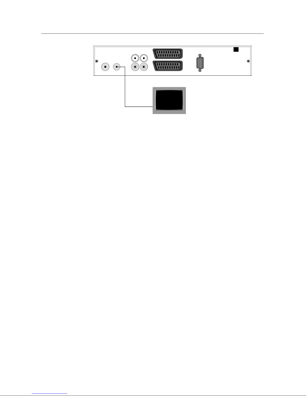
2.4.4 Connecting to The Television by RCA Cable
Plug a RCA cable into the VIDEO (yellow), AUDIO L (white)
and AUDIO R (red) sockets on the digital receiver and the corresponding input sockets on the television or audio appliance.
RS-232
TV OUTANT IN S/PDIF VIDEO
R-AUDIO-L
TV
VCR
2.4.5 Connecting to The Television by RF Cable
Plug a RF cable into the TV OUT socket on the digital receiver
and the corresponding input socket on the television.
Page 14
10 Installation
RS-232
TV OUTANT IN S/PDIF VIDEO
R-AUDIO-L
TV
VCR
2.5 Inserting Batteries in The Remote Control
1. Open the battery compartment by removing the lid.
2. Insert the batteries Observe the polarity (marked on the
base of the battery compartment).
3. Close the battery compartment.
If the digital receiver no longer reacts properly to remote control commands, the batteries may be flat. Be sure to remove
used batteries. The manufacturer accepts no liability for damage resulting from leaking batteries.
Note Batteries, including those which contain no heavy met-
als, may not be disposed of with household waste.
Please dispose of used batteries in an environmentally
sound manner. Find out about the legal regulations
which apply in your area.
2.6 Station Settings
You have to configure station settings according to your antenna system.
Page 15

2.6 Station Settings 11
2.6.1 Service Search
To search services, select the
Installation > Service Search
menu.
Search Mode
There are 3 search modes: Auto, Manual, and SMATV. The Auto
mode enables you to search all the services you can receive.
The Manual mode enables you to search the services in the
channel you want.
Channel
The Channel menu is available only in manual search mode.
The available channels are VHF 6 – 12 and UHF 21 – 69.
FTA/Scrambled
Select the station class you want to search. FTA(Free To Air) is
free, but CAS(Conditional Access System) is not.
Antenna Supply 5V
When using an active antenna, it should be set to On to supply
power to the Amplifier of the Antenna. (5 V/Max 100 mA)
Page 16

12 Installation
Start Search
To start the searching process, press
¤£¡
¢
OK button at this item. To
stop the searching process on the way, press either the
¤
£
¡
¢
MENU
button or the
¤
£
¡
¢
EXIT button. This menu will be shown as long
as the digital receiver is searching for services. All channels
found will be listed in two columns on the screen with TV
services in one column and Radio channels in the other. Please
note that the search procedure may take a few minutes.
When the search procedure is completed, the screen will show
how many TV and Radio channels have been found. Press
¤£¡
¢
OK
button to save the channels.
2.6.2 Factory Setting
All the stored data can be reset just like it was manufactured.
To reset all of the settings and lists, select the Installation >
Factory Setting menu. The Factory Setting will be proceeded
in order of Select your location, Language Setting and Service
Search.
Select your location
Please choose the place where you live.
Language Setting
You can choose one among many languages available.
Page 17

13
Chapter 3
Preference Settings
3.1 Time Setting
To set the local time, select the
System Setting > Local Time
Setting menu.
The exact local current time can
be adjusted by using the Mode,
the Local Time and the Time
Offset submenus.
Mode
By usingb,
d
you can select on of the Auto/Manual mode.
The Auto mode updates the time settings automatically by the
GMT received from the broadcast and the Time Offset you
have inserted. The Auto mode is recommended.
Page 18

14 Preference Settings
Local Time
The Local Time is adjustable only when the Mode is in the
Manual mode. Adjust the current time, if necessary, by using
the numeric buttons andb,dbuttons.
GMT
GMT is referred to the standard time of Greenwich. It cannot
be changed.
Time Offset
The current time of the local area can be inserted. In another
words, insert the time difference of the local time zone from
the GMT. For example, if the local area is Seoul (the time difference from the GMT is 9), insert 9:00. The time is adjustable
by usingb,dbuttons, 15 minutes at a time.
3.2 Timer Setting
To set the timer, select the System Setting > VCR Timer Setting menu.
To insert a new timer entry,
press
¤£¡
¢
F1 button. Press
¤£¡
¢
OK but-
ton to edit the entry, and press
¤£¡
¢
F2 button to delete the selected
entry.
Type: Select TV or Radio by pressingb,dbutton.
Service: Select the service to be reserved for recording by press-
ing
¤£¡
¢
OK button.
Page 19

3.2 Timer Setting 15
Mode: By usingb,
d
buttons, select one among One Time,
Everyday, Every Weekend, Weekly, and Every Weekday.
Date: Select the recording start date by pressingb,
d
but-
tons.
Wakeup Time: Select the wakeup time.b,dbuttons and
¤£¡
¢
0
to
¤£¡
¢
9 buttons are available.
Duration: Select the recording duration by pressingb,dbut-
tons.
OK: To confirm the setting for the reserved recording, press
¤£¡
¢
OK button.
Service Number
Service Name Reseved Date
Wakeup Time
Duration Mode
Page 20

16 Preference Settings
3.3 Access Restriction
To set the access restrictions,
select the System Setting >
Parental Control menu.
Password to various menus can
be configured. The PIN Code
box will automatically appear
when this menu is selected. The
default PIN Code is 0000.
Censorship
The Censorship item blocks programs according to each specific setting. Useb,dbuttons to select the items below.
No Block: Access to everyone.
Total Block: Access to no one without PIN code. If the service
is limitation free, the block function will not work.
4 –18 (age): Inaccessible for viewers within each minimum
age limit if a maturing rating of the event is same or
lower than the age limit. In case of inaccessible, the digital receiver asks the PIN Code and check the age limit.
If the service is limitation free, the block function will not work.
Change PIN Code
Go to the Change PIN Code item to configure new PIN Code.
Press
¤£¡
¢
OK button, then a box will appear on the screen. Enter
the PIN code by using the numeric buttons on your remote
control.
Page 21

3.4 Language Setting 17
Access Control
The Access Control menu controls access to following items:
Time Setting, Language Setting, A/V Output Setting, Organizing Favorites, and so on. To lock a menu, select the Locked en-
try. Locked means controlling the access to the specific menus
with the PIN Code system. The default PIN Code is 0000.
3.4 Language Setting
There are many languages available for the menu, subtitle and
audio. To set the languages, select the System Setting > Lan-
guage Setting menu.
Menu Language
It is an item for changing the language of the Main menu. Select the language that the menus will be shown in.
Subtitle Language
It is an item for changing the language of the subtitle. As long
as the services support it, the subtitle language is changeable
by pressing the subtitle button on your remote control.
Audio Language
It is an item for changing the language of the Audio. If more
than one audio language is transmitted, you may select one
language among the languages transmitted by pressing
button.
Page 22

18 Preference Settings
3.5 Audio and Video Setting
To set the audio and video settings, select the System Setting
> A/V Output Setting menu.
TV Type
Select your TV standard. For automatic PAL/NTSC selection,
set it to Multi.
Video Output
Select the color model for the video output.
VCR SCART Type
Select the VCR SCART type either Standard or External A/V.
In case of External A/V, the source of TV SCART output will
be selected between VCR SCART input and internal AV by
pressing button on the remote control. In case of Standard,
it will be done automatically by the SCART functionality.
TV Aspect Ratio
Select your TV screen format. Select 4:3 or 16:9 mode by using
b,d
buttons.
Page 23

3.6 Menu Transparency 19
Display Format
If you have a TV set with the 4:3 picture format and transmission is in 16:9, you can select the display format. Select the
Letter Box or Center extract by usingb,dbuttons.
Sound Mode
It allows you to configure the sound mode. Select the Stereo,
Mono, Left and Right mode by usingb,dbuttons. The Sound
mode is configurable later on by using the sound button
on your remote control.
RF Output
When the digital receiver is connected to the TV by an RF cable, you may need to select the correct TV standard system.
Select the PAL G, PAL I, PAL K, NTSC M mode by usingb,
d
buttons.
RF Channel
Select a RF channel by usingb,
d
buttons. The default RF
channel is CH36. When you change the RF channel number,
you must also change to the same value on the TV. If you do
not, there will be no picture and sound.
3.6 Menu Transparency
To adjust the transparency level of the menus and the other
on-screen display , select the System Setting > OSD Trans-
parency menu. The available levels are ranging from 0% to
50%.
3.7 Display Time of The Information Box
Refer the information box to Section 5.2 on page 24.
Page 24

20 Preference Settings
To adjust the display time of the information box, select the
System Setting > Info Box Display Time menu. When you select a service to watch, the information box is displayed during the specified time.
3.8 Position of The Information Box
You can raise or lower the position of the information box. To
adjust the position of the information box, select the System
Setting > Info Box Position menu.
Page 25

21
Chapter 4
Listing Services
4.1 Editing The Services List
To edit the service list, select the
Organizing Services menu.
Browse
Press
¤£¡
¢
OK button. Now, browsing through the Organizing Ser-
vices is possible. Press assigned buttons on the help message.
Page 26

22 Listing Services
Rename
Usea,cbuttons to select Rename item and press
¤£¡
¢
OK button
to move the cursor to the Service List. Press
¤£¡
¢
OK button to
display keyboard, and rename the service. After renaming it,
be sure to save it by pressing
¤£¡
¢
OK button at Save item.
Move
You can reorder and move the service to the preferred position. Mark the desired service to move and press
¤£¡
¢
OK button.
Usea,cbuttons to choose the Move mode.
Lock
You can restrain and lock the services. From here, locking (and
later unlocking) services in any of the lists is possible e.g. in
order to prevent children from watching it. If a locked service
is selected, you should enter the PIN code in order to enjoy it.
Delete
Press
¤£¡
¢
OK button to delete services. The delete function dif-
fers from the skip function as it deletes the service completely.
Whereas, the skip function just makes the service invisible.
Note The Delete menu deletes the specified service perma-
nently. The only way to undo it is to perform the service search again.
Sort
You can sort and rearrange the service list.
Page 27

4.2 Editing The Favorites List 23
4.2 Editing The Favorites List
To edit the favorite services list,
select the Organizing Favorties
menu.
On the Fav List mode, four standard lists are selected as the
default menus: News, Movie Music and Sports. Up to 30 lists
including these lists can be added and renamed. When deleting a service, select a service in the Fav Services section and
press the assigned button on the help message.
To add services into Favorites, locate the cursor to the desired
service in Service List and press
¤£¡
¢
OK button. To delete a ser-
vice from Favorites, locate the cursor to the service in Fav Services and press
¤£¡
¢
OK button.
Page 28

24 Daily Usage
Chapter 5
Daily Usage
5.1 Browsing Services
Press
¤£¡
¢
OK button to see the ser-
vice list then the service list with
the help window will be displayed. Select one of the services you want to enjoy.
5.2 Information Box
Press the information button on the remote control to see
the program information. The Information box displays as follows:
Page 29

5.2 Information Box 25
• Service Number
• Service Name
• Detailed Program Infor-
mation
• Signal Level and Quality
• Satellite Information
• Information of subtitle
and teletext
• Parental Lock
You can hide the Information Box by pressing button.
Service Name Frequency Signal Strength
Service Event Name Time CAS, Parental
Number Information Subtitle, Lock
Teletext Mark
Event Description Start Time – End Time / Dolby / Multifeed
You can see the Current/Next event by pressingb,dbutton
in the information box. To control the volume in the information box, you have to pressb/dbutton two times without
interval. If EPG is available on programs, by usingd,bbuttons, you can see the EPG. You can see extended information
of the event by pressing the information button once more.
Page 30

26 Daily Usage
5.3 Electronic Program Guide
To display the information
about currently being broadcasted as well as those that
will be broadcasted next, press
¤
£
¡
¢
GUIDE button on the remote
control unit. If EPG is available
on programs, you will see the
detailed description of the programs, start/end time and programs schedules etc.
a,c
buttons will be used to move program and to see next
program schedules.
d,b
buttons will be used to switch the service.
¤£¡
¢
OK button makes the reservation for the next program. For
a detailed description of the reservation method, refer to Section 3.2 on page 14.
button shows extended information of the event.
button will change the contents of EPG between TV and
Radio services.
¤£¡
¢
F1 button switches the EPG from Single Service to Multi Ser-
vice and in opposition.
5.3.1 Subtitle
You can choose a language of subtitle using the subtitle button
on the remote control. If the broadcaster provides subti-
tles, you can see the subtitle symbol in the Information Box.
5.3.2 Teletext
If the broadcaster supports teletext, you can see the teletext
symbol in the Information Box. There are VBI insertion
mode and software emulation mode in teletext. In the VBI in-
Page 31

5.3 Electronic Program Guide 27
sertion mode, which is always on, you can watch the teletext
with your TV using the remote control of your TV. To watch
teletext with VBI insertion, your TV must support teletext. In
the software emulation mode, you can watch the teletext even
though your TV does not support teletext. You can watch the
teletext using the remote control of digital receiver. Press the
teletext button to watch the teletext with software emulation mode. Press the teletext button once more or
¤
£
¡
¢
EXIT
button to escape from teletext.
5.3.3 Sound Track
You can choose a language
of soundtrack by pressing
the sound button when a
broadcaster supports various
languages of soundtrack. Also,
it is possible to choose a mode
among Stereo, Mono, Left and
Right usingd,bbuttons. The
sound button is used for
multifeed function, too.
If the multifeed is available in current service, Multifeed Track
will be displayed first. You can change the display to Sound
Track selection menu by pressing the sound button once
more.
5.3.4 Multifeed
If multifeed is available in the service, the multifeed symbol
will appear at the right side of the Information box. If
available, the Multifeed Track and Sound Track are toggled
by the sound button . It is possible to choose one of the
multifeed services.
Page 32

28 Firmware Update and Data Transfer
Chapter 6
Firmware Update and Data
Transfer
The digital receiver has a stable and convenience firmware to
use. However, a new firmware may be released to improve the
digital receiver, The latest firmware and the update program
are available at Topfield website http://www.i-topfield.com.
To view the current information of the digital receiver, select
the Information > IRD Status
menu.
Page 33

6.1 Firmware Update 29
6.1 Firmware Update
6.1.1 From a Personal Computer via RS232 Port
It is possible to transfer a new firmware to the digital receiver
from a personal computer connecting them by a RS232 cable
to update the firmware. The firmware transfer program,
TFD-
Down
is needed to use this method of update, which is avail-
able at the Topfield website, http://www.i-topfield.com.
How to update the firmware with this method is as follows.
1. Download a new firmware applicable to the digital re-
ceiver from the Topfield website.
2. Download
TFD-Down
from the Topfield website.
3. Plug a RS232 cable into the RS232 socket on the digi-
tal receiver and the corresponding socket on your computer.
4. Turn on the digital receiver.
5. Run
TFD-Down
.
How to use
TFD-Down
is as follows.
1. Press
¤£¡
¢
Find button to select the new
firmware file.
2. Press
¤
£
¡
¢
Download button to start the file
transfer.
3. Press
¤
£
¡
¢
Stop button to cancel the file
transfer.
6.1.2 From another Digital Receiver via RS232 Port
It is possible to transfer a new firmware to the digital receiver
from another digital receiver connecting them by a RS232 cable to update the firmware only if they are the same model.
Page 34

30 Firmware Update and Data Transfer
How to update the firmware with this method is as follows.
1. Plug a RS232 cable into the RS232 socket on the digital
receiver and the other’s.
2. Turn on them.
3. Select the Installation > Transfer Program to Other IRD
menu .
6.2 Data Transfer
From another Digital Receiver via RS232 Port
It is possible to transfer service information to the digital receiver from another digital receiver connecting them by a RS232
cable only if they are the same model.
How to update the firmware with this method is as follows.
1. Plug a RS232 cable into the RS232 socket on the digital
receiver and the other’s.
2. Turn on them.
3. Select the Installation > Transfer Data to Other IRD menu.
Page 35

31
Appendix A
Information
A.1 Operational Functions and Features
• Fully compliant with MPEG-2 digital and DVB
• 2000 services programmable including radio service
• Multilingual audio supported
• Multilingual menu provided
• Service switching time less than 1 second
• Service list editable
• Favorite service list editable
• Automatic selection of color model
• 256 color on-screen display
• GMT and time offset supported
• Electronic program guide supported
• Subtitle supported
• Teletext supported
• Access restriction function provided
• Firmware update and data transfer available between
the same receivers
• Exciting games embedded
• Timer function provided
Page 36

32 Information
A.2 Technical Specification
Table A.1: Specifications of Tuner & Decoder
Input/Loop through Connector IEC 169-2, Female/Male
Frequency Range VHF 174 to 230 MHz, UHF 470 to 862 MHz
Signal Level Input −78 to −20 dBm
Aerial Supply 5 V, Max. 100 mA
Modulation OFDM
Carrier Mode 2 k and 8 k hierarchical/non-hierarchical
Constellation QPSK,16 and 64 QAM
Guard Interval 1/4, 1/8, 1/16 and 1/32
Table A.2: Specifications of MPEG Transport Stream AV Decoding
Transport Stream ISO/IEC 13818-1 MPEG-2 Transport Stream Specification
Profile Level MPEG-2 MP@ML
Aspect Ratio 4:3, 16:9
Video Resolution 720 × 576
Audio Decoding MPEG-1 layer 1 and 2
Table A.3: Specifications of A/V & Data In/Out
TV-SCART Video CVBS/RGB/YUV output and audio L/R output
VCR-SCART Video CVBS output and audio L/R output
Video CVBS output and audio L/R input for bypass
RCA A/V Video CVBS output and audio L/R output
S/PDIF Digital audio or Dolby AC-3 bitstream output
RS-232 9 pin D-sub type, Transfer rate: 115.2 kbps
Table A.4: Specifications of RF-Modulator
Connector 75 Ω, IEC 169-2, Female/Male
Output Service PAL CH21 – 69, NTSC CH14 – 83
TV standard PAL G/I/K, NTSC-M
Table A.5: Specifications of Power Supply
Input Voltage 90 to 250 VAC, 50/60 Hz
Type SMPS
Power Consumption Running: Max. 10 W, Standby: 9 W
Protection Separate internal fuse.
The input have lightning protection.
Page 37

A.2 Technical Specification 33
Table A.6: Physical Specifications
Size (W × H × D) 260 × 46 × 190 mm
Weight (Net) 1.2 Kg
Page 38

34 IRD Status
Index
Symbol
16:9, 18
4 –18 (age), 16
4:3, 18
A
A/V Output Setting, 18
Access Control, 17
ANT IN, 7
Auto, 11, 13
Auto/Manual, 13
B
Button, 3
Download, 29
EXIT, 12
Find, 29
MENU, 12
Stop, 29
C
CAS, 11
Censorship, 16
Center extract, 19
Change PIN Code, 16
Channel, 11
Conditional Access System, 11
D
Date, 15
Download, 29
Duration, 15
E
Every Weekday, 15
Every Weekend, 15
Everyday, 15
EXIT, 12
External A/V, 18
F
Factory Setting, 12
Fav List, 23
Fav Services, 23
Favorites, 23
Find, 29
Free To Air, 11
FTA, 11
I
Info Box Display Time, 20
Info Box Position, 20
Information, 28
Installation, 11, 12, 30
IRD Status, 28
Page 39

Language Setting Weekly 35
L
Language Setting, 12, 17
Left, 19
Letter Box, 19
Local Time, 13
Local Time Setting, 13
Locked, 17
M
Manual, 11, 14
MENU, 12
Mode, 13, 15
Mono, 19
Movie, 23
Multi, 18
Music, 23
N
News, 23
No Block, 16
NTSC M, 19
O
OK, 15
One Time, 15
Organizing Favorties, 23
Organizing Services, 21
OSD Transparency, 19
P
PAL G, 19
PAL I, 19
PAL K, 19
PAL/NTSC, 18
Parental Control, 16
R
R-AUDIO-L, 7
Rename, 22
Right, 19
RS232, 7, 29, 30
S
S/PDIF, 7
Save, 22
Select your location, 12
Service, 14
Service List, 23
service list, 24
Service Search, 11, 12
SMATV, 11
Sports, 23
Standard, 18
Stereo, 19
Stop, 29
System Setting, 13, 14, 16–20
T
TFD-Down, 29
Time Offset, 13
Total Block, 16
Transfer Data to Other IRD, 30
Transfer Program to Other IRD,
30
TV, 7
TV OUT, 7
Type, 14
V
VCR, 7
VCR Timer Setting, 14
VIDEO, 7
W
Wakeup Time, 15
Weekly, 15
Page 40

36
WEEE Information
Page 41

37
Page 42

38
Page 43

39
Page 44

40
Page 45

41
Page 46

42
Page 47

43
Page 48

Copyright © 2005, TOPFIELD Co., Ltd. English Version
http://www.i-topfield.com 110T-F8829-201-0 Rev. 2
 Loading...