

Page 1
INSTRUCTION MANUAL
AUTOMATIC TRACKING PULSE TOTAL STATION
GPT-8000A
SERVO PULSE TOTAL STATION
SERIES
GPT-8001A
GPT-8002A
GPT-8003A
GPT-8005A
GPT-8000
SERIES
GPT-8001
GPT-8002
GPT-8003
GPT-8005
Page 2

.
AUTO TRACKING TOTAL STATION
GPT-8000A series
SERVO TOTAL STATION
GPT-8000 series
TOPCON POSITIONING SYSTEMS, INC.
5758 West Las Positas Blvd., Pleasanton, CA 94588, U.S.A.
Phone: 925-460-1300 Fax: 925-460-1315 www.topcon.com
TOPCON CALIFORNIA
3380 Industrial Blvd, Suite 105, West Sacramento, CA 95691,
Phone: 916-374-8575 Fax: 916-374-8329
TOPCON MIDWEST
891 Busse Road, Elk Grove Village, IL 60007, U.S.A.
Phone: 847-734-1700 Fax: 847-734-1712
TOPCON EUROPE B.V .
Essebaan 11, 2908 LJ Capelle a/d IJssel, The Netherlands.
Phone: 010-4585077 Fax: 010-4585045 www.topconeurope.com
TOPCON BELGIUM
Preenakker 8, 1785 Merchtem, Belgium
Phone: 052-37.45.48 Fax: 052-37.45.79
TOPCON DEUTSCHLAND G.m.b.H.
Weidkamp 180, 45356 Essen, GERMANY
Phone: 0201-8619-100 Fax: 0201-8619-111 ps@topcon.de
www.topcon.de
TOPCON S.A.R.L.
89, Rue de Paris, 92585 Clichy, Cedex, France.
Phone: 33-1-41069490 Fax: 33-1-47390251 topcon@topcon.fr
U.S.A.
TOPCON ESPAÑA S.A.
HEAD OFFICE
Frederic Mompou 5, ED. Euro 3, 08960, Sant Just Desvern Barcelona, Spain.
Phone: 93-473-4057 Fax: 93-473-3932 www.topconesp.com
MADRID OFFICE
Avenida Burgos, 16E, 1 28036, Madrid, Spain.
Phone: 91-302-4129 Fax: 91-383-3890
TOPCON SCANDINAVIA A. B.
Neongatan 2 S-43151 Mölndal, SWEDEN
Phone: 031-7109200 Fax: 031-7109249
TOPCON CORPORA TION
75-1 Hasunuma-cho, Itabashi-ku, Tokyo 174-8580, Japan
Phone: 3-3558-2520 Fax: 3-3960-4214 www.topcon.co.jp
TOPCON (GREA T
HEAD OFFICE
Topcon House Kennet Side, Bone Lane, Newbury, Berkshire RG14 5PX U.K.
Phone: 44-1635-551120 Fax: 44-1635-551170
survey.sales@topcon.co.uk laser.sales@topcon.co.uk
TOPCON SOUTH ASIA PTE. LTD.
Blk 192 Pandan Loop, Pantech Industrial Complex, #07-01, Singapore 128381
Phone: 62780222 Fax: 62733540 www.topcon.com.sg
TOPCON AUSTRALIA PTY . L TD .
408 Victoria Road, Gladesville, NSW 2111, Australia
Phone: 02-9817-4666 Fax: 02-9817-4654 www.topcon.com.au
TOPCON INSTRUMENTS (THAILAND) CO., LTD.
77/162 Sinn Sathorn T ower, 37th Fl.,
Krungdhonburi Rd., Klongtonsai, Klongsarn, Bangkok 10600 Thailand.
Phone: 662-440-1152~7 Fax: 662-440-1158
TOPCON INSTRUMENTS (MALA YSIA) SDN. BHD .
Lot 226 Jalan Negara 2, Pusat Bandar Taman Melawati,
Taman Melawati, 53100, Kuala Lumpur, Malaysia.
Phone: 03-41079801 Fax: 03-41079796
TOPCON KOREA CORPORA TION
2F Yooseoung Bldg., 1595-3, Seocho-Dong, Seocho-gu, Seoul, 137-876, Korea
Phone: 82-2-2055-0321 Fax: 82-2-2055-0319 www.topcon.co.kr
TOPCON OPTICAL (H.K.) LIMITED
2/F., Meeco Industrial Bldg., No. 53-55 A u Pui W an Street, Fo Tan Road,
Shatin, N.T ., Hong Kong
Phone: 2690-1328 Fax: 2690-2221 www.topcon.com.hk
TOPCON CORPORATION BEIJING OFFICE
Room No. 962 Poly Plaza Building, 14 Dongzhimen Nandajie,
Dongcheng District, Beijing, 100027, China
Phone: 10-6501-4191~2 Fax: 10-6501-4190
TOPCON CORPORATION BEIRUT OFFICE
P. O. BOX 70-1002 Antelias, BEIRUT-LEBANON.
Phone: 961-4-523525/961-4-523526 Fax: 961-4-521119
TOPCON CORPORATION DUBAI OFFICE
P.O.Box 28595, 102, Al Naily Bldg., 245 Abu Hail Road, Deira,Dubai,UAE
Phone: 971-4-2696511 Fax: 971-4-2695272
BRIT AIN) LTD.
64538 90020 GPT- 8000/8000A Series A 0207 (2B)
Page 3

FOREWORD
1
FOREWORD
Thank you for purchasing the TOPCON Auto Tracking Pulse Total Station / Servo Pulse Total
Station, GPT-8000A/8000 series. For the best performance of the instruments, please carefully
read these instructions and keep them in a conve-nient location for future reference.
General Ha nd ling P rec aut i on s
Before starting work or operation, be sure to check that the instrument is functioning
correctly with normal performance.
Do not submerge the instrument into water.
The instrument can not be submerged underwater.
The instrument is designed based on the International Standard IP54, therefore it is protected from
the normal rainfall.
Setting the instrument on a tripod
When mounting the instrument on a tripod, use a wooden tripod when possible. The vibrations that
may occur when using a metallic tripod can effect the measuring precision.
Installing the tribrach
If the tribrach is installed incorrectly, the measuring precision could be effected. Occasionally check
the adjusting screws on the tribrach. Make sure the base fixing lever is locked and the base fixing
screws are tightened.
Guarding the instrument against shocks
When transporting the instrument, provide some protection to minimize risk of shocks. Heavy
shocks may cause the measurement to be faulty.
Carrying the instrument
Always carry the instrument by its handgrip.
Exposing the instrument to extreme heat.
Do not leave the instrument in extreme heat for longer than necessary. It could adversely affect its
performance.
Sudden changes of temperature
Any sudden change of temperature to the instrument or prism may result in a reduction of
measuring distance range, i.e when taking the instrument out from a heated vehicle. Let instrument
acclimate itself to ambient temperature.
Battery level check
Confirm battery level remaining before operating.
Memory back up
The instrument has a built in battery for memory back up. If the battery power is low, “Back up
battery empty” will display. Contact your dealer, to replace the battery.
Taking the battery out
It is recommended not to take the battery out during the power is on. All the data stored is possible
gone at that time. So please do your assembling or taking the battery out after the power is off.
No responsibility
TOPCON Corporation has no responsibility for loss of data stored in the memory in case
unexpected accidents.
Page 4

FOREWORD
2
Rotating the instrument and telescope
Rotation of the instrument or telescope is driven electronically in normal operation.
Do not disturb the rotation.
Storage in the case
Keep the telescope horizontally and turn the instrument to align its mark with the lower base mark
(Storage mark). Keep its objective lens side downward. Storing it in the case in any other way may
cause damage. Hold the hand grips and base with both hands, when taking the instrument out of the
case, or putting the equipment in the case.
Maintenance for driving parts.
Every 4,000~5,000 hours operation in total, change grease of driving parts.
Contact your dealer or TOPCON Head Office for the maintenance.
Page 5
FOREWORD
3
Display for Safe Use
In order to encourage the safe use of products and prevent any danger to the operator and
others or damage to properties, important warnings are put on the products and inserted in
the instruction manuals.
We suggest that everyone understand the meaning of the following displays and icons before
reading the “Safety Cautions” and text.
Display Meaning
WARNING
WARNING
CAUTION
CAUTION
• Injury refers to hurt, burn, electric shock, etc.
• Physical damage refers to extensive damage to buildings or equipment and furniture.
Safety Cautions
•There is a risk of fire, electric shock or physical harm if you attempt to disassemble or
r epair the instrument yourself.
This is only to be carried out by TOPCON or an authorized dealer, only!
•Cause eye injury or blindness.
Do not look at the sun through a telescope.
•Laser beams can be dangerous, and can cause eye injury's if used incorrectly.
Never attempt to repair the instrument yourself. (GPT-8000A series and laser plummet model)
•Cause eye injury or blindness.
Do not stare into beam.
(GPT-8000A series and laser plummet model)
•High temperature may cause fire.
Do not cover the charger while it is charging.
•High temperature may cause fire.
Do not connect the battery to an instrument while it is charging.
•Risk of fire or electric shock.
Do not use damaged power cable, plug and socket.
•Risk of fire or electric shock.
Do not use a wet battery or charger.
•May ignite explosively.
Never use an instrument near flammable gas, liquid matter, and do not use in a coal mine.
•Battery can cause explosion or injury.
Do not dispose in fire or heat.
•Risk of fire or electric shock.
Do not use any power voltage except the one given on manufacturers instructions.
•Battery can cause outbreak of fire.
Do not use any other type of charger other than the one specified.
•Risk of fire.
Do not use any other power cable other than the one specified.
•Battery can cause outbreak of fire.
Do not block up the vent of the battery.
•The short circuit of a battery can cause a fire.
Do not short circuit battery when storing it.
Ignoring or disregard of this display may lead to the danger of death or
serious injury.
Ignoring or disregard of this display may lead to personal injury or phys
-ical damage.
WARNING
WARNING
Page 6

FOREWORD
4
User
1) This product is for professional use only!
The user is required to be a qualified surveyor or have a good knowledge of surveying, in
order to understand the user and safety instructions, before operating, inspecting or adjusting.
2) Wear the required protectors (safety shoes, helmet, etc.) when operating.
Exceptions from Responsibility
Exceptions from Responsibility
1) The user of this product is expected to follow all operating instructions and make periodic
checks of the product’s performance.
2) The manufacturer, or its representatives, assumes no responsibility for results of a faulty or
intentional usage or misuse including any direct, indirect, consequential damage, and loss
of profits.
3) The manufacturer, or its representatives, assumes no responsibility for consequential
damage, and loss of profits by any disaster, (an earthquake, storms, floods etc.).
A fire, accident, or an act of a third party and/or a usage any other usual conditions.
4) The manufacturer, or its representatives, assumes no responsibility for any damage, and
loss of profits due to a change of data, loss of data, an interruption of business etc., caused
by using the product or an unusable product.
5) The manufacturer, or its representatives, assumes no responsibility for any damage, and loss
of profits caused by usage except for explained in the user manual.
6) The manufacturer, or its representatives, assumes no responsibility for damage caused by
wrong movement, or action due to connecting with other products.
CAUTION
CAUTION
Use of controls or adjustment or performance of procedures other than those specified herein
may result in hazardous radiation exposure.(GPT-8000A series and laser plummet model)
Let the laser beam reach the aimed object or the target without anybody else in the laser beam
path. In case you operate laser beam open, avoid radiating laser beam to the height of man's
head. It is quite possible for the beam to enter into one's eyes, and it is possible to lose visual
sight temporarily, and lose one's caution and awareness of other dangers - avoid glaring beam.
(GPT-8000A series and laser plummet model)
Do not connect or disconnect equipment with wet hands, you are at risk of electric shocks if you
do!
Risk of injury by overturn the carrying case.
Do not stand or sit on the carrying cases.
Please note that the tips of tripod can be hazardous, be aware of this when setting up or
carrying the tripod.
Risk of injury by falling down the instrument or case.
Do not use a carrying case with a damaged which belts, grips or latches.
Do not allow skin or clothing to come into contact with acid from the batteries, if this does occur
then wash off with copious amounts of water and seek medical advice.
A plumb bob can cause an injury to a person if used incorrectly.
It could be dangerous if the instrument falls over, please ensure you attach a handle battery to
the instrument securely.
Ensure that you mount the Tribrach correctly, failing to do so may result in injury if the tribrach
were to fall over.
It could be dangerous if the instrument falls over, please check that you fix the instrument to the
tripod correctly.
Risk of injury by falling down a tripod and an instrument.
Always check that the screws of tripod are tightened.
Page 7
FOREWORD
5
Laser Safety
•
Distance measurement
GPT-8000A/8000 series uses the invisible laser beam to measure the distance. The GPT-8000A/8000
series are manufactured and sold in accordance with "Performance Standards for Light-Emitting
Products" (FDA/BRH 21 CFR 1040) or "Radiation Safety of Laser Products, Equipment Classification,
Requirements and User`s Guide" (IEC Publication 60825-1) provided on the safety standard for laser
beam.
As per the said standard, the GPT-8000 series is classified as "Class 1 (l) Laser Products".
In case of any failure, do not disassemble the instrument. Contact TOPCON or your
TOPCON dealer.
•
GPT-8000A series
GPT-8000Aseries uses the visible laser beam for auto tracking and optical communication. The
GPT-8000Aseries products are manufactured and sold in accordance with “Radiation Safety of Laser
Products, Equipment Classification, Requirements and User‘s Guide” (IEC Publication 60825-1) or
“Performance Standards for Light-Emitting Products” (FDA/BRH 21 CFR 1040) provided on the safety
standards for laser beam.
As per the said standards, GPT-8000Aseries is classified as “Class 2 (CLASS II) Laser Products”.
The laser beam belongs not very dangerous type but we request you to keep and understand “Safety
standard for users” as mentioned in the manual instruction.
In case of any failure, do not disassemble the instrument. Contact TOPCON or your
TOPCON dealer.
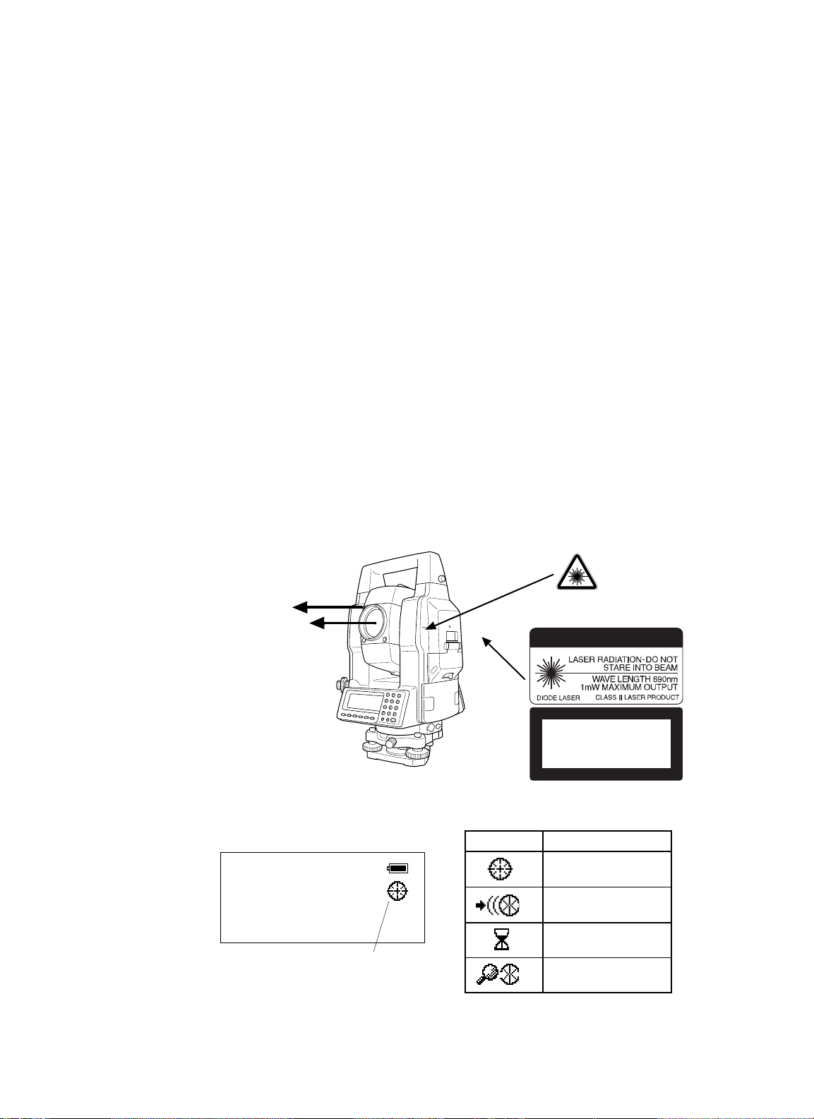
Labels
Find the labels which describes the caution and safety about the laser beam as follows in GPT-8000A
series. We request you to replace it one anytime the caution labels are damaged or lost and paste a
new one at the same place. You can get the labels from Topcon or
your dealer.
Beam aperture
ent
Beam aperture
GPT-8000A series
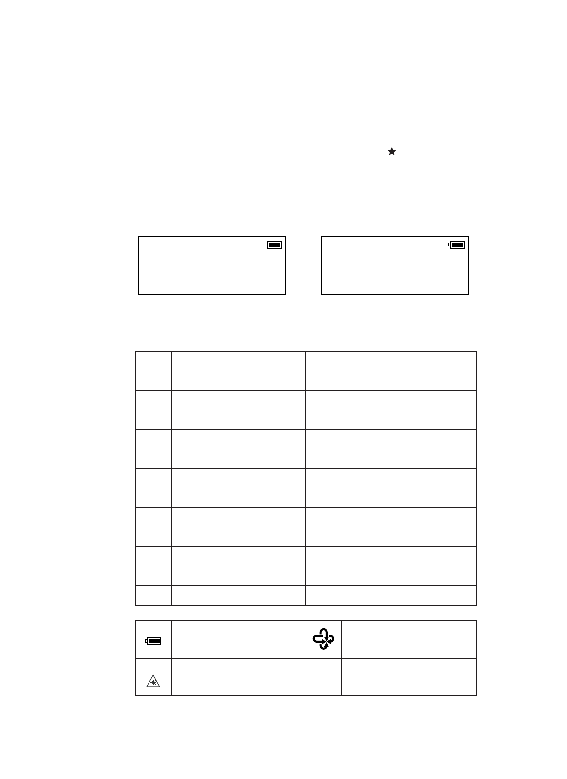
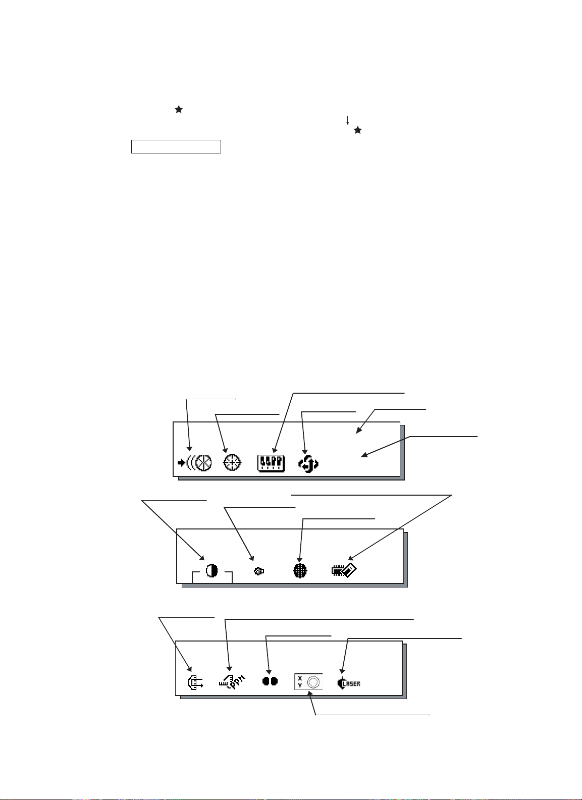
Symbol marks while the laser is emitting.
The following symbol marks of instrument status will indicate that the laser is emitting.
Marks Status of instrum
V : 87°55'45"
HR: 180°44'12"
SD HD NEZ 0SET HOLD P1↓
The symbol mark
Warning Label
Explanatory Label
CAUTION
LASER RADIA TION
DO NOT STARE INTO BEAM
Maximum output 1mW Wave length 690nm CW
CLASS 2 LASER PRODUCT
Each label is differed by the market.
Auto-collimating
Auto-tracking
Waiting
Searching
Page 8
FOREWORD
6
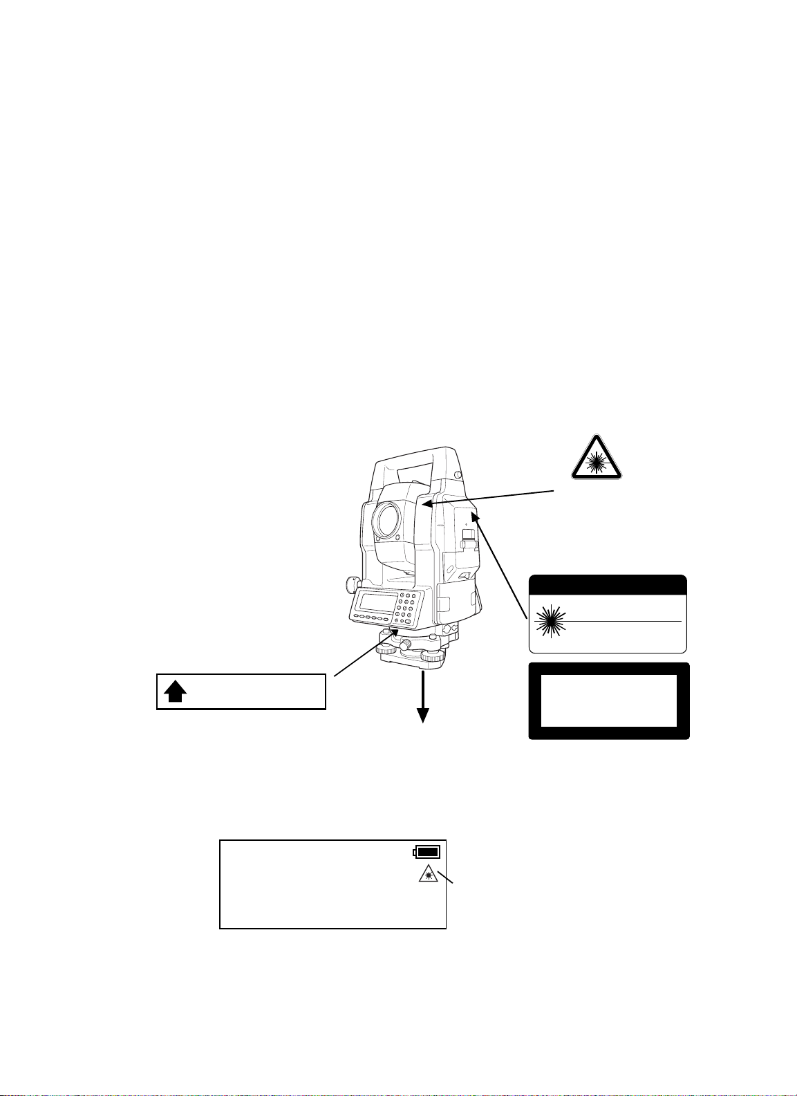
•
Laser Plummet Model
GPT-8000A/8000 series Laser plummet model use a visible laser beam to perform the plumb laser
function. The GPT-8000A/8000 series Laser plummet type products are manufactured and sold in
accordance with "Radiation Safety of Laser Products, Equipment Classification, Requirements and
User`s Guide" (IEC Publication 60825-1) or "Performance Standards for Light-Emitting Products"
(FDA/BRH 21 CFR 1040) regarding the safety standard for laser products.
As per these standards, the GPT-8000A/8000 series Laser plummet type is classified as "Class II (2)
Laser Products".
Since Laser radiation is emitted from the GPT-8000A/8000 series Laser plummet type instruments,
please refer to the "Laser Safety" bulletin which accompanies the instrument in the United States as
well as the "Safety Standard for Users" that is mentioned in the instruction manual.
In the case of any technical failure, do not disassemble the instrument. Contact either TOPCON or
your authorized TOPCON dealer.
Labels
The following labels are found on the instruments which describe the GPT-8000A/8000 series
Laser plummet type: Precautions and safety information about the laser beam.
If, at any time, any of these labels are damaged and become illegible, please replace these
important labels. Please the new labels in exactly the same position as the original labels.
Replacement labels can be obtained from Topcon or your authorized Topcon dealer.
Depending on the country where the instrumetn is sold, either of these labels may be
found on the GPT-8000A/8000 series laser plummet type.
Symbol mark while the laser is emitting.
The following symbol mark willappear at the right side of the second line.
The symbol mark will blink while the laser
plummet is working.
Warning Label
GPT-8000A/8000 series
Laser Plummet type
P1
Ap
erture Label
AVOID EXPOSURE
LASER LIGHT IS EMITTED
FROM THIS APERTURE
Beam aperture
V : 87°55'45"5
HR: 180°44'12"5
SD HD NEZ 0SET HOLD
P1
↓
Explanatory Label
CAUTION
LASER RADIA TION-DO NOT
STARE INTO BEAM
WAVE LENGTH 633n m
1mW MAXIMUM OUTPUT
CLASS II LASER PRODUCT
LASER RADIATION
DO NOT STARE INTO BEAM
Maximum output 1mW Wave length 633nm
CLASS 2
LASER PRODUCT
Page 9

FOREWORD
7
Contents
FOREWORD . . . . . . . . . . . . . . . . . . . . . . . . . . . . . . . . . . . . . . . . . . . . . . . . 1
General Handling Precautions . . . . . . . . . . . . . . . . . . . . . . . . . . . . . . . . . . . . . . . . . . . . 1
Display for Safe Use . . . . . . . . . . . . . . . . . . . . . . . . . . . . . . . . . . . . . . . . . . . . . . . . . . . 3
Safety Cautions . . . . . . . . . . . . . . . . . . . . . . . . . . . . . . . . . . . . . . . . . . . . . . . . . . . . . . . 3
User . . . . . . . . . . . . . . . . . . . . . . . . . . . . . . . . . . . . . . . . . . . . . . . . . . . . . . . . . . . . . . . 4
Exceptions from Responsibility . . . . . . . . . . . . . . . . . . . . . . . . . . . . . . . . . . . . . . . . . . . 4
Laser Safety . . . . . . . . . . . . . . . . . . . . . . . . . . . . . . . . . . . . . . . . . . . . . . . . . . . . . . . . . 5
Contents . . . . . . . . . . . . . . . . . . . . . . . . . . . . . . . . . . . . . . . . . . . . . . . . . . . . . . . . . . . .7
Standard Set Composition . . . . . . . . . . . . . . . . . . . . . . . . . . . . . . . . . . . . . . . . . . . . . . . 9
1 NOMENCLATURE AND FUNCTIONS . . . . . . . . . . . . . . . . . . . . . . . . . . . 1-1
1.1 Nomenclature . . . . . . . . . . . . . . . . . . . . . . . . . . . . . . . . . . . . . . . . . . . . . . . . . . . . . 1-1
1.2 Display . . . . . . . . . . . . . . . . . . . . . . . . . . . . . . . . . . . . . . . . . . . . . . . . . . . . . . . . . . 1-3
1.3 Operating Key . . . . . . . . . . . . . . . . . . . . . . . . . . . . . . . . . . . . . . . . . . . . . . . . . . . . . 1-4
1.4 Function Key (Soft Key) . . . . . . . . . . . . . . . . . . . . . . . . . . . . . . . . . . . . . . . . . . . . . . 1-5
1.5 Star key mode . . . . . . . . . . . . . . . . . . . . . . . . . . . . . . . . . . . . . . . . . . . . . . . . . . . . . 1-7
1.6 Auto Power Off . . . . . . . . . . . . . . . . . . . . . . . . . . . . . . . . . . . . . . . . . . . . . . . . . . . . 1-12
1.7 Data Output . . . . . . . . . . . . . . . . . . . . . . . . . . . . . . . . . . . . . . . . . . . . . . . . . . . . . . . 1-12
1.8 Rotating Method . . . . . . . . . . . . . . . . . . . . . . . . . . . . . . . . . . . . . . . . . . . . . . . . . . . 1-12
1.8.1 Rotating by H/V Shuttle and H/V Jog . . . . . . . . . . . . . . . . . . . . . . . . . . . . . . . 1-12
1.8.2 Auto Inversion . . . . . . . . . . . . . . . . . . . . . . . . . . . . . . . . . . . . . . . . . . . . . . . . 1-12
1.8.3 Rotating automatically to a required Horizontal and Vertical angle . . . . . . . . . 1-13
1.9 Using together with RC-2II Remote Control System
(GPT-8000Aseries) . . . . . . . . . . . . . . . . . . . . . . . . . . . . . . . . . . . . . . . . . . . . . . . . . . . . 1-14
1.10 Using connecting with Personal Computer (PC) . . . . . . . . . . . . . . . . . . . . . . . . . . . 1-15
2 PREPARATION FOR MEASUREMENT . . . . . . . . . . . . . . . . . . . . . . . . . . 2-1
2.1 Power Connection . . . . . . . . . . . . . . . . . . . . . . . . . . . . . . . . . . . . . . . . . . . . . . . . . . 2-1
2.2 Setting Instrument Up For Measurement . . . . . . . . . . . . . . . . . . . . . . . . . . . . . . . . . 2-2
2.3 Power Switch Key ON . . . . . . . . . . . . . . . . . . . . . . . . . . . . . . . . . . . . . . . . . . . . . . . 2-3
2.4 Battery Level Indicator . . . . . . . . . . . . . . . . . . . . . . . . . . . . . . . . . . . . . . . . . . . . . . 2-4
2.5 Main Menu Icons . . . . . . . . . . . . . . . . . . . . . . . . . . . . . . . . . . . . . . . . . . . . . . . . . . . 2-5
2.6 Vertical and Horizontal Angle Tilt Correction . . . . . . . . . . . . . . . . . . . . . . . . . . . . . . . 2-6
2.7 Compensation of Systematic Error of Instrument . . . . . . . . . . . . . . . . . . . . . . . . . . . 2-7
2.8 Resume Mode ON/OFF . . . . . . . . . . . . . . . . . . . . . . . . . . . . . . . . . . . . . . . . . . . . . . 2-8
2.9 How to Enter Numerals and Alphabet Letters . . . . . . . . . . . . . . . . . . . . . . . . . . . . . . 2-8
2.10 Memory Card . . . . . . . . . . . . . . . . . . . . . . . . . . . . . . . . . . . . . . . . . . . . . . . . . . . . . 2-9
2.11 Inclination of Prism and Measuring Error (GPT-8000A series) . . . . . . . . . . . . . . . . . 2-10
3 AUTOMATIC TRACKING / AUTOMATIC COLLIMATION
(GPT-8000A series . . . . . . . . . . . . . . . . . . . . . . . . . . . . . . . . . . . . . . . . . . 3-1
3.1 Automatic Tracking . . . . . . . . . . . . . . . . . . . . . . . . . . . . . . . . . . . . . . . . . . . . . . . . . 3-1
3.2 Automatic Collimation . . . . . . . . . . . . . . . . . . . . . . . . . . . . . . . . . . . . . . . . . . . . . . . 3-3
3.3 Range of Laser for Auto-tracking and Auto-collimating . . . . . . . . . . . . . . . . . . . . . . . 3-4
3.4 Setting Parameters for Auto-Tracking . . . . . . . . . . . . . . . . . . . . . . . . . . . . . . . . . . . . 3-5
3.4.1 Setting Items . . . . . . . . . . . . . . . . . . . . . . . . . . . . . . . . . . . . . . . . . . . . . . . . . 3-5
3.4.2 How to set the parameters . . . . . . . . . . . . . . . . . . . . . . . . . . . . . . . . . . . . . . 3-7
4 STANDARD MEASUREMENT MODE . . . . . . . . . . . . . . . . . . . . . . . . . . . . 4-1
4.1 Angle Measurement . . . . . . . . . . . . . . . . . . . . . . . . . . . . . . . . . . . . . . . . . . . . . . . . . 4-1
4.1.1 Measuring Horizontal Angle Right and Vertical Angle . . . . . . . . . . . . . . . . . . . 4-1
4.1.2 Switching Horizontal Angle Right/Left . . . . . . . . . . . . . . . . . . . . . . . . . . . . . . 4-2
4.1.3 Measuring from the Required Horizontal Angle . . . . . . . . . . . . . . . . . . . . . . . 4-2
4.1.4 Vertical Angle Percent Grade(%) Mode . . . . . . . . . . . . . . . . . . . . . . . . . . . . . 4-3
4.1.5 Automatic Rotation to a Required Horizontal and Vertical Absolute Angle . . . . 4-4
4.2 Distance Measurement . . . . . . . . . . . . . . . . . . . . . . . . . . . . . . . . . . . . . . . . . . . . . . 4-5
4.2.1 Setting of the Atmospheric Correction . . . . . . . . . . . . . . . . . . . . . . . . . . . . . . 4-5
4.2.2 Setting of the Correction for Prism Constant / Non-prism Constant . . . . . . . . . 4-5
4.2.3 Distance Measurement (Continuous Measurement) . . . . . . . . . . . . . . . . . . . . 4-6
4.2.4 Distance Measurement (Single/N-times Measurement) . . . . . . . . . . . . . . . . . 4-7
4.2.5 Fine / Coarse Measuring Mode . . . . . . . . . . . . . . . . . . . . . . . . . . . . . . . . . . . 4-9
4.2.6 Stake Out (S-O) . . . . . . . . . . . . . . . . . . . . . . . . . . . . . . . . . . . . . . . . . . . . . . 4-10
4.3 COORDINATE MEASUREMENT . . . . . . . . . . . . . . . . . . . . . . . . . . . . . . . . . . . . . . . 4-11
Page 10

FOREWORD
8
4.3.1 Setting Coordinate Values of Occupied Point . . . . . . . . . . . . . . . . . . . . . . . . . 4-11
4.3.2 Setting of the Instrument Height / Prism Height . . . . . . . . . . . . . . . . . . . . . . . 4-13
4.3.3 Execution of Coordinate Measuring . . . . . . . . . . . . . . . . . . . . . . . . . . . . . . . . 4-14
4.4 DATA OUTPUT . . . . . . . . . . . . . . . . . . . . . . . . . . . . . . . . . . . . . . . . . . . . . . . . . . . . 4-16
5 PROGRAM MODES . . . . . . . . . . . . . . . . . . . . . . . . . . . . . . . . . . . . . . . . . 5-1
5.1 Setting a Direction Angle for Backsight Orientation . . . . . . . . . . . . . . . . . . . . . . . . . . 5-2
5.2 Retaining a Coordinate (STORE- NEZ) . . . . . . . . . . . . . . . . . . . . . . . . . . . . . . . . . . 5-3
5.3 Remote Elevation measurement (REM) . . . . . . . . . . . . . . . . . . . . . . . . . . . . . . . . . . 5-5
5.4 Missing Line Measurement (MLM) . . . . . . . . . . . . . . . . . . . . . . . . . . . . . . . . . . . . . . 5-8
5.5 Line Measurement (LINE) . . . . . . . . . . . . . . . . . . . . . . . . . . . . . . . . . . . . . . . . . . . . 5-11
5.6 Offset measurement (OFFSET) . . . . . . . . . . . . . . . . . . . . . . . . . . . . . . . . . . . . . . . . 5-14
5.6.1 Angle Offset . . . . . . . . . . . . . . . . . . . . . . . . . . . . . . . . . . . . . . . . . . . . . . . . . 5-15
5.6.2 Distance Offset Measurement . . . . . . . . . . . . . . . . . . . . . . . . . . . . . . . . . . . . 5-17
5.6.3 Plane Offset Measurement . . . . . . . . . . . . . . . . . . . . . . . . . . . . . . . . . . . . . . 5-19
5.6.4 Column Offset Measurement . . . . . . . . . . . . . . . . . . . . . . . . . . . . . . . . . . . . . 5-21
5.7 External Link (GPT-8000Aseries) . . . . . . . . . . . . . . . . . . . . . . . . . . . . . . . . . . . . . . 5-23
5.7.1 Starting compatible communication program of AP-L1A . . . . . . . . . . . . . . . . 5-23
5.7.2 Setting for the communication . . . . . . . . . . . . . . . . . . . . . . . . . . . . . . . . . . . . 5-23
5.7.3 Carrying out Communication . . . . . . . . . . . . . . . . . . . . . . . . . . . . . . . . . . . . . 5-27
6 MEMORY MANAGE MODES . . . . . . . . . . . . . . . . . . . . . . . . . . . . . . . . . . 6-1
6.1 View Internal Memory and Card Memory Status . . . . . . . . . . . . . . . . . . . . . . . . . . . . 6-1
6.2 Protect a File . . . . . . . . . . . . . . . . . . . . . . . . . . . . . . . . . . . . . . . . . . . . . . . . . . . . . . 6-2
6.3 Rename a File . . . . . . . . . . . . . . . . . . . . . . . . . . . . . . . . . . . . . . . . . . . . . . . . . . . . . 6-2
6.4 Deleting a File . . . . . . . . . . . . . . . . . . . . . . . . . . . . . . . . . . . . . . . . . . . . . . . . . . . . . 6-3
6.5 Copy a File . . . . . . . . . . . . . . . . . . . . . . . . . . . . . . . . . . . . . . . . . . . . . . . . . . . . . . . 6-3
6.6 Initializing Memory . . . . . . . . . . . . . . . . . . . . . . . . . . . . . . . . . . . . . . . . . . . . . . . . . . 6-4
7 COMMUNICATION MODES . . . . . . . . . . . . . . . . . . . . . . . . . . . . . . . . . . . 7-1
7.1 Setting of PROTOCOL . . . . . . . . . . . . . . . . . . . . . . . . . . . . . . . . . . . . . . . . . . . . . . . 7-1
7.2 Data File In . . . . . . . . . . . . . . . . . . . . . . . . . . . . . . . . . . . . . . . . . . . . . . . . . . . . . . . 7-2
7.3 Data File Out . . . . . . . . . . . . . . . . . . . . . . . . . . . . . . . . . . . . . . . . . . . . . . . . . . . . . . 7-2
8 PARAMETERS SETTING MODE . . . . . . . . . . . . . . . . . . . . . . . . . . . . . . . 8-1
8.1 Parameter Setting Options . . . . . . . . . . . . . . . . . . . . . . . . . . . . . . . . . . . . . . . . . . . . 8-1
8.1.1 Parameters for Measurement and Display . . . . . . . . . . . . . . . . . . . . . . . . . . . 8-1
8.1.2 Parameters for communication . . . . . . . . . . . . . . . . . . . . . . . . . . . . . . . . . . . . . . . 8-2
8.2 Setting Parameters . . . . . . . . . . . . . . . . . . . . . . . . . . . . . . . . . . . . . . . . . . . . . . . . . 8-4
8.2.1 Parameters for Measurement and Display . . . . . . . . . . . . . . . . . . . . . . . . . . . 8-4
8.2.2 Parameters for Communication . . . . . . . . . . . . . . . . . . . . . . . . . . . . . . . . . . . 8-5
8.2.3 Password Option . . . . . . . . . . . . . . . . . . . . . . . . . . . . . . . . . . . . . . . . . . . . . . 8-6
9 CHECK AND ADJUSTMENT . . . . . . . . . . . . . . . . . . . . . . . . . . . . . . . . . . 9-1
9.1 Checking and Adjusting of Instrument Constant . . . . . . . . . . . . . . . . . . . . . . . . . . . . 9-1
9.1.1 Checking of the accuracy of the non-prism mode . . . . . . . . . . . . . . . . . . . . . . 9-1
9.2 Checking the Optical Axis . . . . . . . . . . . . . . . . . . . . . . . . . . . . . . . . . . . . . . . . . . . . 9-2
9.3 Checking/Adjusting the Theodolite Functions . . . . . . . . . . . . . . . . . . . . . . . . . . . . . . 9-4
9.3.1 Checking /Adjusting the Plate Level . . . . . . . . . . . . . . . . . . . . . . . . . . . . . . . . 9-5
9.3.2 Checking /Adjusting the Circular Level . . . . . . . . . . . . . . . . . . . . . . . . . . . . . . 9-5
9.3.3 Adjustment of the Vertical Cross-hair . . . . . . . . . . . . . . . . . . . . . . . . . . . . . . . 9-6
9.3.4 Collimation of the Instrument . . . . . . . . . . . . . . . . . . . . . . . . . . . . . . . . . . . . 9-7
9.3.5 Checking / Adjusting the Optical Plummet Telescope . . . . . . . . . . . . . . . . . . . 9-8
9.3.6 Checking / Adjusting the Laser Plummet (For Laser Plummet type) . . . . . . . . 9-9
9.4 Adjustment of Compensation Systematic Error of Instrument . . . . . . . . . . . . . . . . . . 9-10
9.5 Showing Constant List and Switch ON/OFF
Compensation Systematic Error of Instrument . . . . . . . . . . . . . . . . . . . . . . . . . . . . 9-12
9.6 How to adjust the date and time . . . . . . . . . . . . . . . . . . . . . . . . . . . . . . . . . . . . . . . . 9-13
9.7 How to Set the Instrument Constant Value . . . . . . . . . . . . . . . . . . . . . . . . . . . . . . . . 9-14
9.8 Inspection and Adjustment of Optic Axis for Auto -Tracking
(GPT-8000ASeries) . . . . . . . . . . . . . . . . . . . . . . . . . . . . . . . . . . . . . . . . . . . . . . . . 9-15
10 SETTING THE PRISM / NON-PRISM CONSTANT VALUE . . . . . . . . . . . 10-1
11 SETTING ATMOSPHERIC CORRECTION . . . . . . . . . . . . . . . . . . . . . . . 11-1
11.1 Calculation of Atmospheric Correction . . . . . . . . . . . . . . . . . . . . . . . . . . . . . . . . . . 11-1
11.2 Setting of Atmospheric Correction Value . . . . . . . . . . . . . . . . . . . . . . . . . . . . . . . . . 11-1
Page 11

FOREWORD
9
12 CORRECTION FOR REFRACTION AND EARTH CURVATURE . . . . . . . 12-1
12.1 Distance Calculation Formula. . . . . . . . . . . . . . . . . . . . . . . . . . . . . . . . . . . . . . . . . 12-1
13 POWER SOURCE AND CHARGING . . . . . . . . . . . . . . . . . . . . . . . . . . . 13-1
13.1 Rechargeable Battery BT-56Q . . . . . . . . . . . . . . . . . . . . . . . . . . . . . . . . . . . . . . . . 13-1
14 DETACH/ATTACH OF TRIBRACH . . . . . . . . . . . . . . . . . . . . . . . . . . . . . 14-1
15 BATTERY SYSTEM . . . . . . . . . . . . . . . . . . . . . . . . . . . . . . . . . . . . . . . . 15-1
16 PRISM SYSTEM . . . . . . . . . . . . . . . . . . . . . . . . . . . . . . . . . . . . . . . . . . . 16-1
17 PRECAUTIONS . . . . . . . . . . . . . . . . . . . . . . . . . . . . . . . . . . . . . . . . . . . 17-1
18 ERROR DISPLAYS . . . . . . . . . . . . . . . . . . . . . . . . . . . . . . . . . . . . . . . . . 18-1
19 SPECIAL ACCESSORIES . . . . . . . . . . . . . . . . . . . . . . . . . . . . . . . . . . . 19-1
20 SPECIFICATIONS . . . . . . . . . . . . . . . . . . . . . . . . . . . . . . . . . . . . . . . . . 20-1
APPENDIX . . . . . . . . . . . . . . . . . . . . . . . . . . . . . . . . . . . . . . . . . APPENDIX-1
Dual Axis Compensation ............................................................................................ APPENDIX-1
Precaution when Charging or Storing Batteries.......................................................... APPENDIX-3
Standard Set Composition
1) GPT-8000A/8000 series (with lens cap) . . . . . . . . . . . . . . . . . . . . . . . . . . . . . . . . . 1 each
2) Battery BT-56Q . . . . . . . . . . . . . . . . . . . . . . . . . . . . . . . . . . . . . . . . . . . . . . . . . . . 1 each
3) Battery charger BC-27BR or BC-27CR . . . . . . . . . . . . . . . . . . . . . . . . . . . . . . . . . 1 each
4) Tool kit with case [ rod pins, screwdriver, cleaning brush ] . . . . . . . . . . . . . . . . . . . 1 set
5) Plastic carrying case . . . . . . . . . . . . . . . . . . . . . . . . . . . . . . . . . . . . . . . . . . . . . . . 1 each
6) Silicon cloth . . . . . . . . . . . . . . . . . . . . . . . . . . . . . . . . . . . . . . . . . . . . . . . . . . . . . 1 each
7) Plastic rain cover . . . . . . . . . . . . . . . . . . . . . . . . . . . . . . . . . . . . . . . . . . . . . . . . . 1 each
8) Instruction manual . . . . . . . . . . . . . . . . . . . . . . . . . . . . . . . . . . . . . . . . . . . . . . . . 1 each
(Make sure that all of the above items are with the instrument when purchased.)
Remarks:
1) Battery charger BC-27CR is for AC 230V use and BC-27BR is for AC 120V use.
2) Plumb bob set and plumb bob hook are supplied for certain markets.Remarks:
Page 12
1 NOMENCLATURE AND FUNCTIONS
1-1
1 NOMENCLATURE AND FUNCTIONS
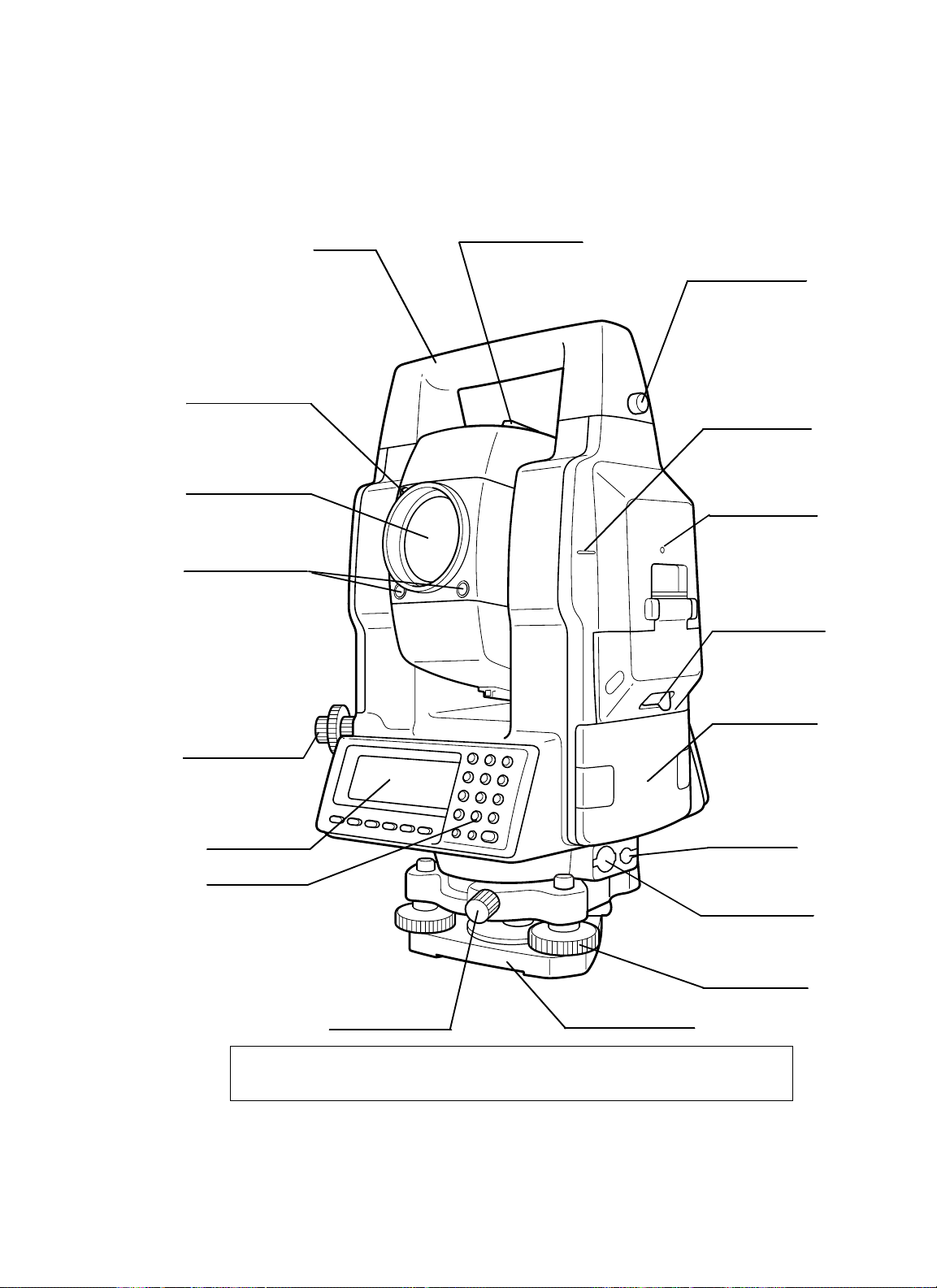
1.1 Nomenclature
Laser aperture
(for optical
communication)
(GPT-8000A series)
Objective lens
Laser aperture
(for auto-tracking)
(GPT-8000A series)
Tracking indicator
(GPT-8000A series)
Point guide
(GPT-8000 series)
Handle
Sighting collimator
Handle fi xing knob
Instrument height
mark
Instrument center
mark
Card cover lever
.
Optical plummet
telescope
Display window
Operation keys
The caution l abels are past ed up GPT-8000A series and Laser plummet mo del which describe
the warning of laser beam.
Refer to " Lase r Safety" and "Laser plum me t model" about l abe l posi ti o ns and their shapes
Base fixing screw
Battery BT-56Q
Power suppl y
connector
Serial Signal
Connector-1(6pin)
Leveling screw
Base (Model 5)
Page 13
1 NOMENCLATURE AND FUNCTIONS
1-2
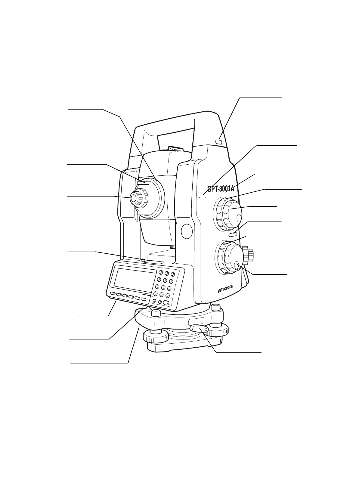
Telescope
focusing knob
Battery fixing knob
Instrument height
mark
Telesco pe gri p
Telescope eyepi ece
Plate level
Centronics
connector
Circular level
Instrument center
mark
Vertical shuttle
Vertical jog
Power switc
Horizontal shuttle
h
Horizontal jog
Adjusting screws for
circul ar level
Tribrach fixing lever
Page 14
1 NOMENCLATURE AND FUNCTIONS
1-3
1.2 Display
• Display
In general upper four lines display the measuring data, and the bottom line displays the soft key
function which is changed by the measuring mode.
• Contrast
The contrast and illumination of display window are adjusted by star ( ) key.
• Heater (Automatic)
The built-in heater keeps the display functional when the temperature goes below 0°C (32 °F). To
switch the heater ON or OFF, refer to Chapter 8 "PARAMETERS SETTING MODE". When the
heater is ON and the temperature goes below 0°C (32 °F), the heater automatically
adjust the temperature to the display to keep it operating.
• Example
Angle measurement mode
V-angle: 87º55’45”
H-angle: 180º44’12”
Distance measurement mode
Horizontal-angle: 87º55’45”
Horizontal distance: 180º44’12”
Relative elevation: 12.345m
V : 87°55'45"
HR: 180°44'12"
SD HD NEZ 0SET HOLD P1
Display Contents Display Content
VV-angle(m)Meter unit
V% Percent grade ( f) Feet unit
HR H-angle right F Fine mode
HL H-angle left C Coarse mode (1m m)
HD Horizontal distance c Coarse mode (10mm)
VD Relative elevation R Repeat measurement
SD Slope distance S Single measurement
NN coordinate N N-times measurement
↓
V : 87°55'40"
HR: 180 °44'12" PSM 0.0
SD: 12.345 PPM 0.0
(m) *F.R
MEAS MODE VH HD NEZ
↓
EE coordinate ppm Atmosphe ric correction value
ZZ coordinate PSM Prism constant value
*EDM workingNPM Non-Prism constant value
NP Non-prism mode
Battery Level Indicator
Refer to Section 2.4 “Battery Lev e l
Indicator” for further information.
Laser plum me t is work ing.
(Only for lase r pl ummet model)
Rotation Indicator
Refer to Section 1.8 “Rotating
Method” for further information.
Page 15

1 NOMENCLATURE AND FUNCTIONS
1-4
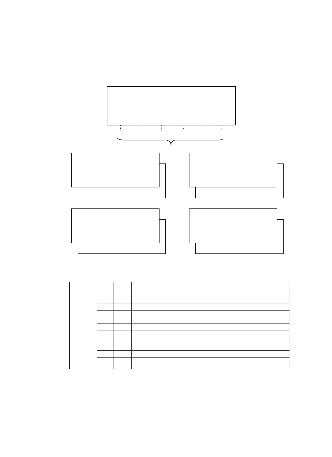
• The symbol marks for Auto-tracking and Auto-collimating (GPT-8000A series)
1.3 Operating Key
Auto-collimating
(
Laser is emitting
GPT-8000A s eries is in autocollimating status.
Waiting (Laser is emitting)
GPT-8000A series is in waiting
status.
Failure in auto-collimating.
(
Laser is off
GPT-8000A series could not find
the target prism during autocollimating.
)
Auto-tracking
)
(
Laser is emitting
GPT-8000A series is in au totracking status.
Searching (Laser is emitting)
GPT-8000A series is searc hing
a prism.
)
KEY NAME FUNCTION
F1~F6 Soft key Functions are ac cording to the displayed message.
0~9 . - Numeric key Numeric Character Entry for Preset Data
A ~/ Alp ha key Alpha Characte r Entry
ESC Escape key Escape to Previous Display or Menu
Star key Optional instrument functions
ENTEnter key End operat i on of data input and accept s data
POWER Power key
ON/OFF of power sou rce.
(Power key is locate d on the side of the instrument.
Page 16
1 NOMENCLATURE AND FUNCTIONS
1-5
1.4 Function Key (Soft Key)
The Soft Key Functions are labeled on teh bottom of display. Soft Key functions are different for
each measurement).
V : 87°55'45"5
HR: 180°44'12"5
SD HD NEZ 0SET HOLD
P1
↓
[F1] [F2] [F3] [F4]
V : 87°55'45"5
HR: 180°44'12"5
SD HD NEZ 0SET HOLD P1
TURN HSET R/L V/% TILT P2
Angle measuring
V : 90 10'20"5
HR: 120 30'40"5 PSM 0.0
HD: PPM 0.0
VD: (m) F.R
MEAS MODE VH SD NEZ P1
REC SO MEAN P2
Horizontal distance measuring
Page D isplay
Angle
measuring
NEZ F3 Coordinate distanc
0SET F4 Set horizontal angle to 0¡00’00".
HOLD F5 Horizontal angle hold.
TURN F1 Turns the instrument to required angle automatically.
HSET F2 Preset a horizonta l angle .
V/% F4 Changes the display to vertical angle or percent of grade.
TILT F5
Soft
key
SD F1 Slope dista nce measuring mode.
HD F2 Horizontal distance measuring mode.
R/L F3 Changes horizontal angle right or left.
Sets the tilt function, ON/OFF.
If ON, the display shows tilt correction value.
Soft keys
↓
↓
P1
↓
↓
e measuring mode.
[F5]
[F6]
V : 90°10'20"5
HR: 120°30'40"5 PSM 0.0
SD: PPM 0.0
(m) F.R
MEAS MODE VH HD NEZ
TURN SO MEAN m/ft P2
Slope distance measuring
N : 12345.6789
E : -12345.6789 PSM 0.0
Z : 10.1234 PPM 0.0
(m) F.R
MEAS MODE VH SD HD P1
↓
TURN HT MEAN P2
Coordinate measuring
Function
↓
↓
↓
Page 17

1 NOMENCLATURE AND FUNCTIONS
1-6
Page Display
Slope
distance
measuring
Horizontal
distance
measuring
Coordinate
measuring
Soft
key
MEAS F1
MODE F2 Changes Fine / Coarse(1mm) /Coarse(10mm) mode.
VH F3 Angle measurement mode.
HD F4
NEZ F5
TURN F1 Turns the instrument to required angle automatically.
SO F2 Stake out measurem ent mode .
MEAN F3 Sets the number of N-time measur ement.
m/ft F4 Changes distance measurement unit to meter or feet.
MEAS F1
MODE F2 Changes Fine / Coarse(1mm) /Coarse(10mm) mode.
VH F3 Angle measurement mode.
SD F4
NEZ F5
TURN F1 Turns the instrument to required angle automatically.
SO F2 Stake out measurem ent mode .
MEAN F3 Sets the number of N-time measur ement.
m/ft F4 Switches meter or feet unit.
MEAS F1
MODE F2 Changes Fine / Coarse(1mm) /Coarse(10mm) mode.
VH F3 Angle measurement mode.
SD F4
HD F5
TURN F1 Turns the instrument to required angle automatically.
HT F2 Input Instrument / prism height values.
MEAN F3 Sets the number of N-t i me meas u rement.
m/ft F4 Switches meter or feet unit.
SET F5 Pre-set instrument coordi nate v alues
Starts slope distan ce measurement mode.
Changes Continuous/ N-times (single) measurement mode.
Horizontal distance measurement mode. Displays the horizontal distance
data after N-times or single measurement.
Coordinate measurement mode.
Displays the coordinate after N-times or single measurement.
Starts horizont al d ist ance measurement mode .
Changes continuous/ N-times (single) measurement mode.
Slope distance measuring mode.
Display the slope distance after N-time
Coordinate measurement mode.
Displays the coordinate after N-times or single measurement.
.
Starts coordinate measurement mode.
Changes continuous/ N-times (single) measurement mode.
Slope distance measuring mode.
Display the slope distance after N-t imes or single measurement.
Horizontal distance measurement mode. Displays the horizontal distance
data after N-times or single measurement.
Function
s or single measurement.
Page 18
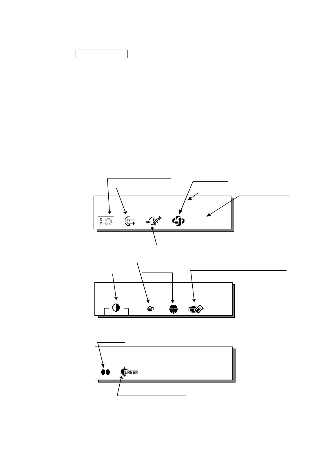
1.5 Star Key Mode
Press the ( ) key to view the instrument options. Since there are three screens (GPT-8000Aseries)
or two screens (GPT-8000 series) of options, press [F6](1 ) soft key to view the next screen.
The following instrument options can be selected from the ( ):
GPT-8000A Series
• Screen One
1) View Date & Time
2) Auto-tracking [F1]
3) Auto-collimating [F2]
4) Set the parameters for Auto-tracking. [F3]
5) Auto- inversion [F4]
6) Non-prism mode / Prism mode selection [F5]
• Screen Two
7) Adjustment the contrast of the display [F1 & F2]
8) Turn the back light of the display ON/OFF [F3]
9) Reticle illumination---Off / Low / Medium / High [F4]
10) View free memory for internal and card memory [F5]
• Screen Three
11) The light acceptance quantity level (signal level) is displayed.[F1]
12) Set the Temperature, Pressure, Atmospheric Correction Value (PPM), and Prism
Constant Value (PSM) [F2]
13) Turn the Tracking Indicator option ON/OFF [F3]
14) Electric circular graphic display [F5]
15) Turn the Laser plummet option ON/OFF [F5] (only for Laser plummet model)
1 NOMENCLATURE AND FUNCTIONS
1-7
2002-07-07 14:30:40
1
↓
2002-07-07 14:30:40
2
↓
Back Light of Display
Auto- inversion
Date & Time
Set para meter for Au to-tr ack ing
Auto-collimating
Auto-tracking
2002-07-07 14:30:40
3
↓
Contrast adjustment
T
racking in dicator
Set the Temperature, Pressure, Atmospheric Correction
Value (PPM), and Prism Constant Value (PSM)
Displaying
Signal Level
Screen 1
Screen 2
Screen 3
View free memory for Card/Internal Memory
Reticle illumination
Laser Plummet
(Only for Laser Plummet type)
Electric circular graphic display
NP/P
Non-prism/ Prism
mode
Page 19
1 NOMENCLATURE AND FUNCTIONS
1-8
GPT-8000A Series
• Screen One
1) View Date & Time
2) Electric circular graphic display [F1]
3) The light acceptance quantity level (signal level) is displayed [F2]
4) Set the Temperature, Pressure, Atmospheric Correction Value (PPM), and Prism
Constant Value (PSM)[F3]
5) Auto- inversion [F4]
6) Non-prism mode / Prism mode selection [F5]
• Screen Two
7) Adjustment the contrast of the display [F1 & F2]
8) Turn the back light of the display ON/OFF [F3]
9) Reticle illumination---Off / Low / Medium / High [F4]
10) View free memory for internal and card memory [F5]
• Screen Three
11)Turn the Point Guide option ON/OFF.[F1]
12) Turn the Laser plummet option ON/OFF [F1] (only for Laser plummet model)
Electric circular graphic display
Displaying Signal Level
Back Light of Display
Contrast adjustment
● Only for Laser Plummet type
Point guide
2002-07-07 14:30:40
2002-07-07 14:30:40
Auto- inversion
Date & Time
↓
e
Set the Temperature, Pressure, Atmospheric Correction
Value (PPM), and Prism Constant Val ue (PSM)
Reticle
illumination
NP/P
View free memory for the Card/Internal Memory
1
↓
2
Non-prism/ Pri sm mod
Screen 1
Screen 2
2001-07-10 14:30:40
Laser Plummet
(Only for Laser Plummet type)
Screen 3
3
↓
Page 20
1 NOMENCLATURE AND FUNCTIONS
1-9
1) View Date & Time
The date and time can be viewed on both screens. To change the displayed order of the date,
(Date/Month/Year), (Month / Date / Year) or (Year/Month/Date), see Chapter 8 “PARAMETERS SETTING MODE” .
To set the date and time, see Chapter 9 “CHECK AND ADJUSTMENT”.
2) Turn the auto-tracking ON/OFF (GPT-8000A series)
Press the [F1] key to start auto-tracking. See Section 3.1 “Automatic Tracking” .
3) Turn the auto-collimating ON/OFF (GPT-8000A series)
Press the [F2] key to start auto-collimating. See Section 3.2 “ Automatic Collimation” .
4) Set the parameters for the auto-tracking (GPT-8000A series)
A proper setting for each parameter such as tracking pattern, tracking range, waiting time, trackingspeed and tracking sensitivity. See Section 3.4 “Setting Parameters for
Auto-Tracking” .
5) Auto Inversion
Pressing the [F4] key causes the instrument to reverse and turn the telescope and
instrument automatically.
•To stop auto rotating in case of emergency, press any keys except POWER key.
• During auto rotation, do not disturb the instrument.(Stopping the rotation with a touch of the hand).
Such action may cause trouble or harm to instrument or operator.
6) Adjustment the contrast of the display
This enable you to adjust the contrast of the display.
Press the [F6] key to get to Screen 2 on the display.
Press the [F1] or [F2] key to brighten or dim the display.
7) Turn the display back light ON/OFF
When the back light is OFF, the light bulb icon is dark.
Press the [F6] key to get to Screen 2 on the display.
To turn the back light ON, press the [F3] key. Press [F3] again to turn the back light OFF.
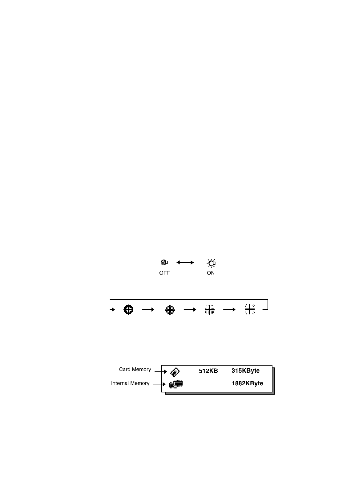
8) Reticle illumination (OFF/Low/Middle/High)
Press the [F6] key to get to Screen 2 on the display. Press the [F4] key to turn the reticle illumination
ON. Continuing to press [F4] will change the intensity options.
9) View free memory
The amount of free memory for the card or internal memory can be displayed.
Press the [F6] key to get to Screen 2 on the display.
Press the [F5] key to view free memory.
The card memory icon (top left side of the display) shows the size of the card and the amount of free
memory. The second icon shows the amount of free internal memory.
See Chapter 6 “MEMORY MANAGE MODES”, for further options and instructions.
Low
OFF
Middle
High
Page 21
1 NOMENCLATURE AND FUNCTIONS
1-10
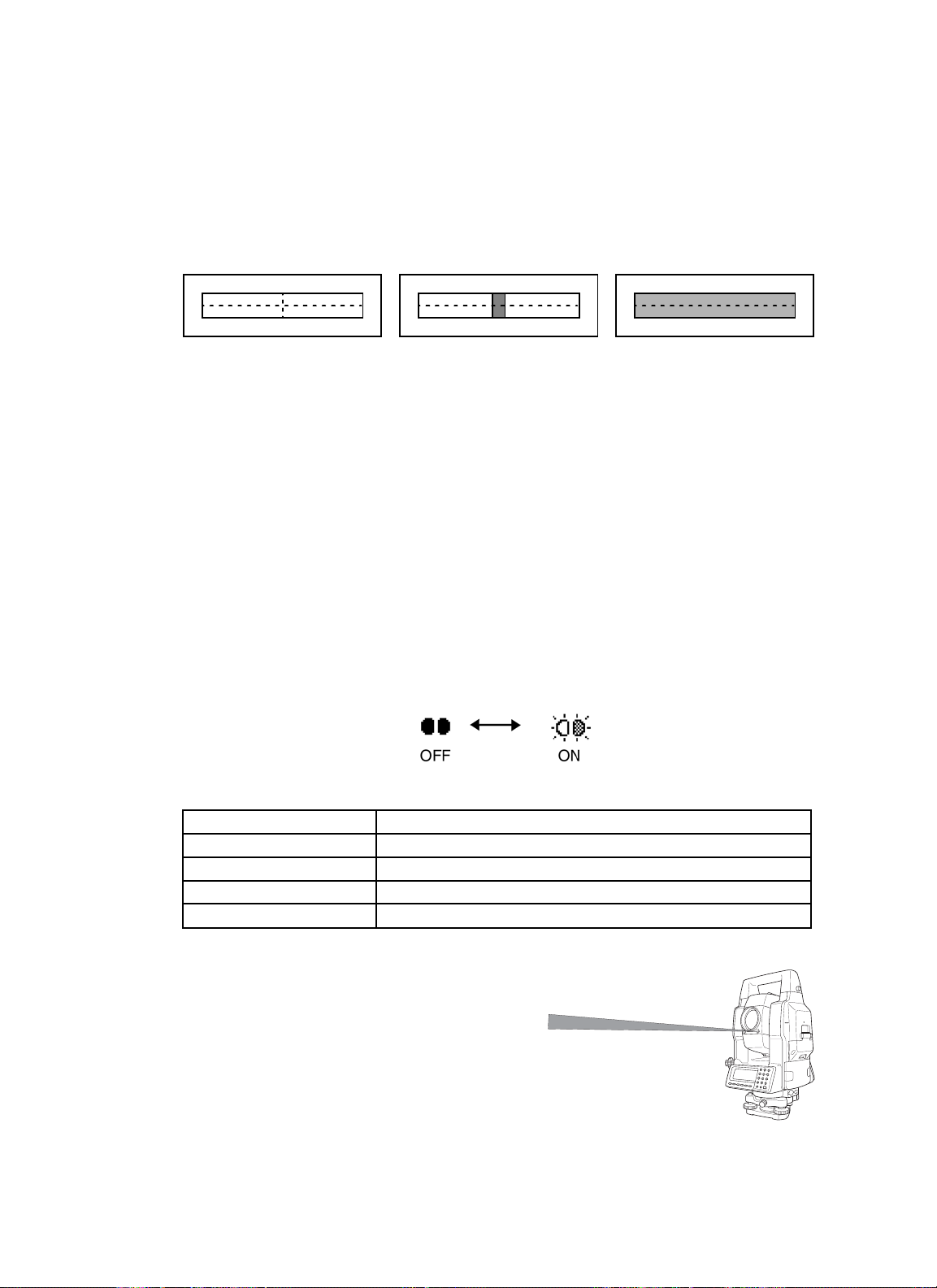
10) Set audio mode
The light acceptance quantity level (Signal level) is displayed in this mode.
When reflected light from the prism is received, a buzzer sounds. This function is good for easy
collimation when the target is difficult to find.
Press the [F1] key on screen 3 (GPT-8000Aseries) or [F2] key on screen 1 (GPT-8000 series).
The received return signal level is displayed with bar graph as follows.
(1) To stop the buzzer, see Chapter 8 “PARAMETERS SETTING MODE”.
(2) Also, it is possible to display the signal level in Distance Measuring Mode.
11) Setting Temperature, Pressure, Atmospheric correction value (PPM), Prism
constant value (PSM)
The temperature, pressure, PPM, and PSM can be viewed by pressing the [F2] key on screen 3
(GPT-8000Aseries) or [F3] key on screen 1 (GPT-8000 series).
The received return signal level is displayed with bar graph as follows.
Refer to Chapter 10 “SETTING THE PRISM / NON-PRISM CONSTANT VALUE” and Chapter 11
“SETTING ATMOSPHERIC CORRECTION”, for further instructions.
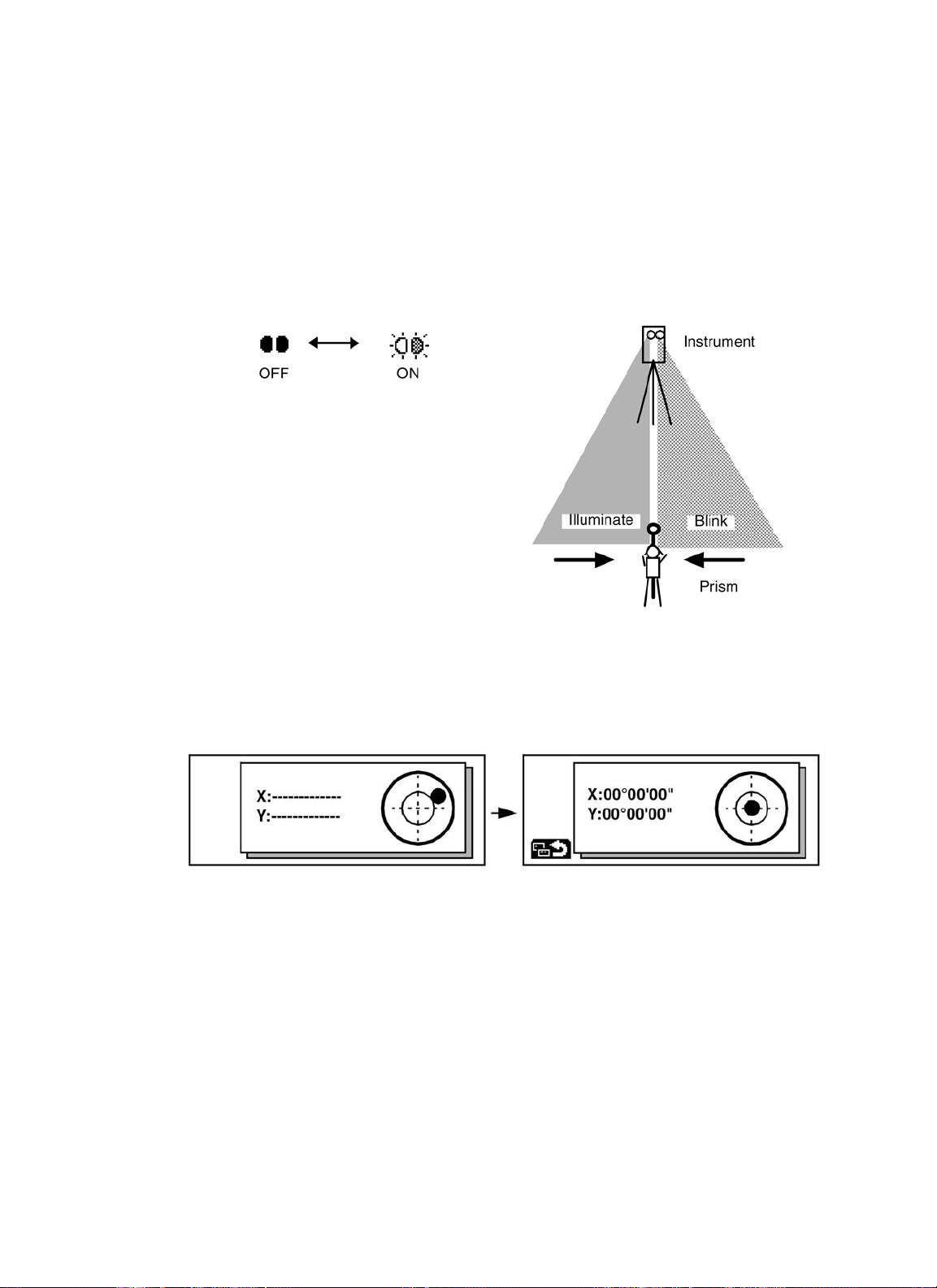
12) Tracking Indicator (GPT-8000A series)
A man who is staying on line with the direction of GPT-8000Aseries or automatic tracking status
by emitted LED light (orange color) from GPT-8000Aseries.
• Operation
Pressing [F3] key on the screen three functions Tracking Indicator. The tracking indicator status
will be changed according to the type of auto tracking mode and its conditions. Aman from the
prism side can recognize the status of instrument.
When angle measuring value turns stable during tracking still object, the tracking indicator
changes from quick continuous flashing to quick intermittent flashing. So you can decide from the
sign of flashing for recording data timing at one person surveying.
Meaning of Tracking Indicator ON or Flashing
• The function of the Tracking Indicator will be
used as a guide to know the status of GPT8000A series from the prism side. This is not a
function to determine precise collimating for
measuring.
• The quality of its results will depend on the
weather conditions and the use's eyesight.
• Sometimes happens difficulty of seeing the
tracking indicator because too much bright of
the beam for tracking.
• Using Tracking Indicator mode will result shorter
in reduced time out of the battery.
No light acceptance
Minimum quantity level
Maximum quantity leve
Tracking Indicator Status of instrume nt
Continuous ON Wait status
Slow flash ing Manual mode
Quick continuous flashing In case angle measuring value is instable during auto tracking mode.
Quick intermittent flashing In case angle measuring value is stable during auto tracking mode.
Page 22
1 NOMENCLATURE AND FUNCTIONS
1-11
13) Point-guide (Point guide type of GPT-8000 series only)
This feature is most useful when doing stake out work. The Point Guide's red LEDs on the
GPT-8000 Series telescope assist the rod person in getting on-line. The Point Guide feature is fast
and simple to use.
•Operating Instructions
Press the [F1] key on the screen three to turn ON the Point Guide LEDs. The Point guide icon on the
display will become bright when turned ON. Looking the objective lens of the telescope, the right LED
will blink and the left LED will stay lit.
The Point Guide should be used within a distance of 100 meters (328 ft.). The quality of its
results will depend on the weather conditions
and the use's eyesight.
The goal of the rod person is to look at both
LEDs on the instrument and move the prism
on-line until both LEDs become equally bright .
If the solid LED is brighter, move to the right. If
the blinking LED is brighter, move to the left.
14) Electric circular level graphic display
Electric circular level can be displayed by graphic. This function is good for level the instrument
when the circular level is difficult to see directly.
Press the [F4](GPT-8000Aseries) on the screen three or [F1] (GPT-8000 series) on the screen one
key to display the graphic.
In the displays of reverse side, the graphic bubble moves in reverse.
Rotate the leveling screws while observing the display.
After leveling, press [F1]. The display changes to the previous mode.
Page 23
1 NOMENCLATURE AND FUNCTIONS
1-12
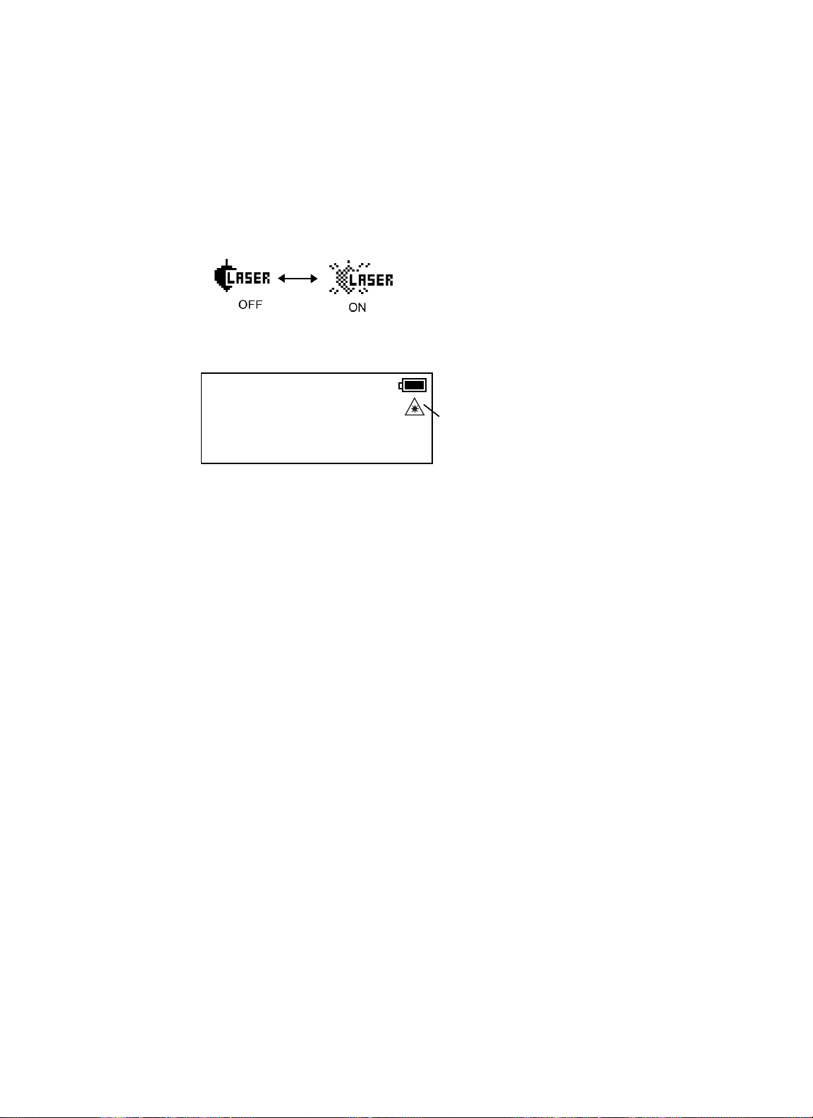
15) Laser Plummet (Only for Laser Plummet type)
Laser plummet option will help you to center the instrument easily onto the measurement point.
Press the star key to view the instrument options. Since there are three screens of options, press
[F6](•) soft key twice to view the screen 3.
Press the [F1] key (GPT-8000 series) or [F5] key (GPT-8000A series) to turn on/off of laser plummet option.
Laser plummet icon will change as follows.
Symbol mark while the laser is emitting.
The following symbol mark will indicate that the laser is emitting.
Laser Plummet auto-cut off function
The laser plummet will be turned off automatically after 1 to 99 minutes (Default:3 minutes). It is
also possible to stop the auto-cut off function.
Refer to Chapter 8 “PARAMETERS SETTING MODE” to change the time or to invalidate the
function.
1.6 Auto Power Off
The Auto Power OFF feature can be set from 1 to 99 minutes. If no keys are pressed within the set
time, the Auto Power OFF will automatically turn the instrument OFF in order to save the
battery time.
See Chapter 8 “PARAMETERS SETTING MODE”, for further instructions.
1.7 Data Output
When GPT-8000A/8000 series receives data output command from an external
connected device, the measured data will be output by GPT-8000A/8000 series. Select
from the following 2 ways for the output. (For setting, see Chapter 8 “PARAMETERS
SETTING MODE” .)
REC-A : The measurement is started and new data is output.
REC-B : The data being displayed is output.
1.8 Rotating Method
1.8.1 Rotating by H/V Shuttle and H/V Jog
H/V shuttle or H/V jog can be used to rotate the instrument manually. The shuttle movement or
displacement is proportional in speed and size of angle desired. Asmall, slow turn of the shuttle will
result in a slow small angle displaced. Likewise, a larger abrupt turn of the shuttle will result in a
coarse angle displacement. H/V jog can be used for accurate collimating of the target much like a
standard tangent screw.
1.8.2 Auto Inversion
Pressing the [F4] key in Star Key mode causes the instrument to reverse and turn the telescope and
instrument automatically.
•To stop auto rotating by auto inversion key in case of emergency, press any keys except
POWER key.
V : 87°55'45"5
HR: 180°44'12"5
SD HD NEZ
The symbol mark will blink while the laser
plummet is working
↓
Page 24
1 NOMENCLATURE AND FUNCTIONS
1-13
• During auto rotation, don't disturb the instrument.(Stopping the rotation with a touch of the
hand). Such action may cause trouble or harm to instrument or operator.
See Section 1.5 “Star key mode” for further instructions.
1.8.3 Rotating automatically to a required Horizontal and Vertical angle
In Standard Measurement Modes, the instrument can be rotated automatically by input a required
horizontal and/or vertical angle.
For further instructions, see Section 4.1.5 “Automatic Rotation to a Required Horizontal and Vertical
Absolute Angle” .
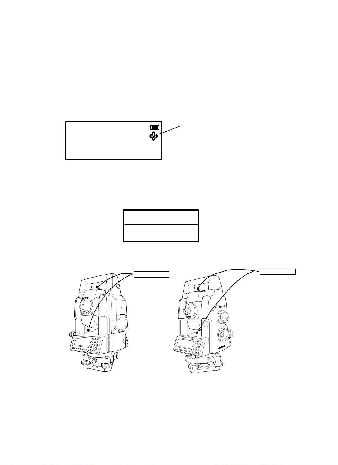
• Attaching Precaution Label
Attach 4 precaution labels to the instrument in specified places to avoid the unexpected
accident such as pinching fingers between telescope and body of instrument or telescope
and hand grip during automatic rotation.
• Attach upper side of telescope and near the plate level.
V : 87°55'45"5
This mark will appear while the
instrument is rotating automat ically.
HR: 180°44'12"5
SD HD NEZ 0SET HOLD P1
Caution label
↓
CAUTION
Do not place fingers near
telescope during rotation.
● Attach upper side of telescope and nea r the pla t e le vel
Caution label
Caution l abel
Page 25
1 NOMENCLATURE AND FUNCTIONS
1-14
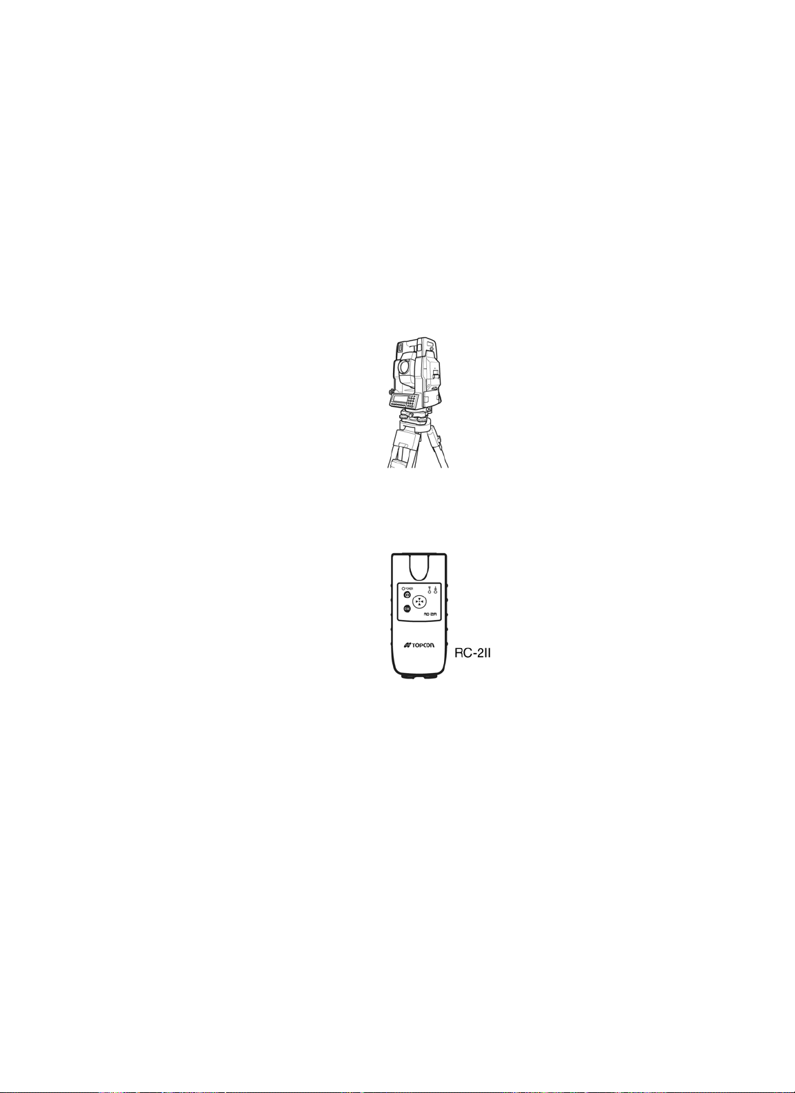
1.9 Using together with RC-2II Remote Control System
(GPT-8000A series)
Using together with RC-2II Remote Control System makes it possible to optical communicate
between the instrument and remote controller RC-2II, the prism side. This gives easy operation by
one man surveying in applying programs.
Also connecting data collector to remote controller, you can manage communication reciprocally
between the instrument and direct to data collector.
Turn-round function
You can turn the GPT-8000A series round to the remote controller RC-2II side easily by [Turn-round]
key of the remote controller RC-2II. This function helps to increase one man surveying efficiency.
See to Section 5.7 “External Link (GPT-8000Aseries)” and Chapter 8 “PARAMETERS SETTING
MODE” for further information.
• Set the transmit path to " RC".
• Set the transmit channel same as RC-2II side.
•To execute transmission, set the remote in Programs mode to [Remote].
Page 26
1 NOMENCLATURE AND FUNCTIONS
1-15
1.10 Using connecting with Personal Computer (PC)
Commands for tracking mode correspond only to GPT-8000A series.
The auto-tracking function or auto collimating function makes easy remote control of the instrument
from PC. The followings are the main communication commands and explanations. How to communicate or more informations of communication command, you can see the interface manual which provided optionally.Commands for tracking mode correspond only to GPT-8000A series. The auto-tracking function or auto collimating function makes easy remote control of the instrument from PC. The followings are the main communication commands and explanations. How to communicate or more
informations of communication command, you can see the interface manual which provided optionally.
Commands Action of GPT-8000A series
Transmit
command
Mode setting
Trans m i t command for measured data
Trans m i t command for tracking mode
Trans m i t command for battery level The ba ttery level will be out put.
Trans m i t command for coordinate of
instrument point
Trans m i t command for tracking
parameter
Setting of angle measurement
Setting of distance measurement
Setting coordinate of instrument point Setting the coordinate of instrument point.
Setting the tracking parameter
Each measured data will be out put
according to the com man d ty pe.
The status of Automatic Tracking mode
will be out put.
Setting coordinate of instrument point will
be out pu t .
Each setting trac king parameter of
instrument will be out put acc or d ing to the
command type.
Each selecting mode in horizontal angle
or angle measurement can be decided
according to the purpose of comm and.
Setting the measurement mode for
distance measurement.
Setti ng each tracki ng parameter
according to the com man d.
Action
T.I. ON / OFF ON / OFF of Tracking indicator.
Rotating command Rotating of s ett ing angle.
Inversion Inversion movement.
Setting tracki ng mode
Setting from automatic tracking mode to
each command mode.
Page 27
2 PREPARATION FOR MEASUREMENT
2-1
2 PREPARATION FOR MEASUREMENT
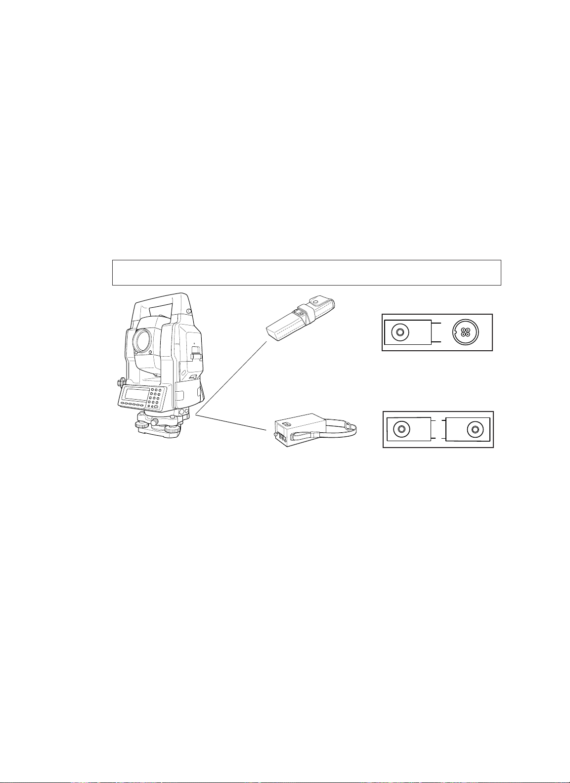
2.1 Power Connection
(unnecessary if on-board Ni-MH battery BT-56Q is used)
See below for connecting the external battery pack.
• Battery pack BT-3Q
Power cord , PC-5 is used.
• Large capacity battery pack BT-3L
Power cord PC-6 is used.
• When using a external battery, the rechargeable battery BT-56Q should be attached
(The instrument will lack in balance if the internal battery BT-56Q is removed.)
The external battery and the internal battery can be used at the same time. The GPT-8000A/8000
series will select a battery due to the battery remaining automatically.
Connector ends
PC-5
PC-6
BT-3Q
BT
-3L
PC-5
PC-6
Page 28
2 PREPARATION FOR MEASUREMENT
2-2
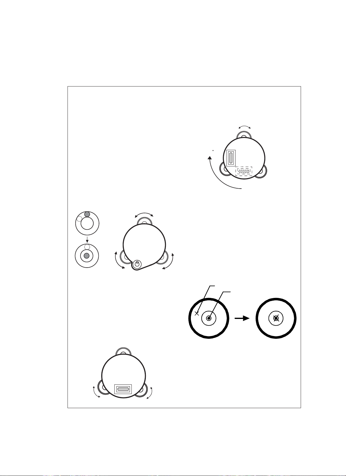
2.2 Setting Instrument Up For Measurement
Mount the instrument to the tripod. Level and center the instrument precisely to insure the best performance. Use tripods with a tripod screw of 5/8 in. diameter and 11 threads per inch, such as the
Type E TOPCON wide- frame wooden tripod.
Reference: Leveling and Centering the Instrumen
1. Setting up the T r ipod
First, e xtend the e xtension legs to suitable lengths
and tighten the screws on their mid sections.
2. Attaching the Instrument on the Tripod
Head
Place the instrument carefully on the tripod head
and slide the instrument by loosening the tripod
screw . If the plumb bob is positioned right over the
center of th e point, slightly ti gh ten t he tripod
screw.
3. Roughly Le veling the Instru men t by Using
the Circular Level
1Turn the leveling screws A and B to move the
bubble in the circular level. The bubble is now
located on a line per pendicular to a line
running throug h the centers o f the tw o le ve ling
screws being adjusted.
Leveling screw C
Leveling
screw A
2Turn the leveling screw C to bring the bubble
to the center of the circul ar l e vel.
4. Centering by Using the Plate Level
1Rotate the instrument horizon tally by using
the Horizontal motion/clamp screw and place
the plate level par allel with the line connecting
leveling screws A and B, and then bring the
bubble to the center of the plate level by
turning leveling screws A and B.
Leveling screw B
2Rotate the instrument 90
ver tical axis and turn the remaining leveling
screw or C to center the bubble once more.
90
3Repeat the procedures 1 and 2 for each 90
(100g) rotation of the instrument and check
whethe r t he bubble i s correctly cente red f o r all
four points.
5. Centering b y Usin g the Optical Plummet
Telescope
Adjust t he e y epiece of the optical plumm et
telescope to your ey esight.
Slide the instrument by loosening the tripod
t
screw, place the point on the cent er mark, and
then tighten the tripod screw. Sliding the
instrument carefully not to rotate that allows you
to get the least dislocation of the bubbl e.
Point
°
(100g) around its
Leveling screw C
Center mark
°
Leveling
screw A
6. Completely Leveling the Instrument
Lev el i ng the instrum ent precisely in a simila r way
to 4. Rotate the instrument and check to see that
the bub ble is in the center of t he plate level
regardless o f telescope dir ecti on, then tighten th e
tripod screw hard.
Leveling
screw B
Page 29
2 PREPARATION FOR MEASUREMENT
2-3
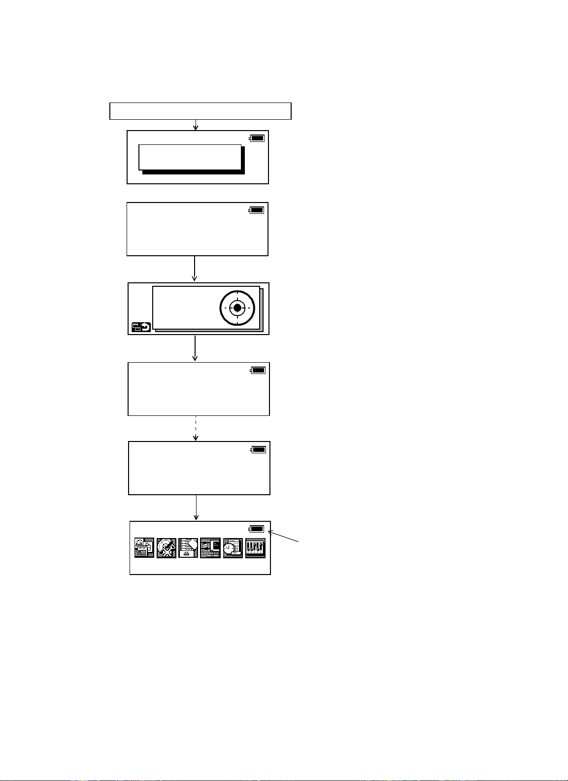
2.3 Power Switch Key ON
1) Confirm the instrument is leveled.
2) Turn the power switch ON.
3) Type your password.
Self checking mode will display.
To skip the self checking, press [F1](ESC)
key.
Level the instrument by turning the leveling
screws.
When the leveling is within ±30" and stable,
the self checking will start.
The instrument will turn automatically and
the tilt sensor offset value will be measured
and memorized.
After checking, the main menu icons will be
shown.
Battery Power Remaining Display
• Self checking option
The self checking function is to check internal communication and tilt sensor offset value. When
ambient temperature is changed or the instrument is not balanced by its internal battery is attached
or detached, the self checking is recommended.
• Password option
Setting a password (Maximum 10 digits number) and activating ON of password option can be helpful to avoid miss operation by unauthorized operator. Setting password option is necessary to use
this function. To set password option, see Chapter 8 “PARAMETERS SETTING MODE”.
• Confirm the battery power remaining on the display. Replace with charged battery or charge
when battery level is low. Refer to Section 2.4 “Battery Level Indicator”.
Power O N
Input a password
[ ]
Self check mode
ESC
X:00°00'00"
Y:00°00'00"
Self checking ...
[ 1/6 ]
ng
Self checki
2002-07-07 14:30
Prog Std Mem Com
...
[ 6/6 ]
Main menu icons
Adj
Para
Page 30
2 PREPARATION FOR MEASUREMENT
2-4
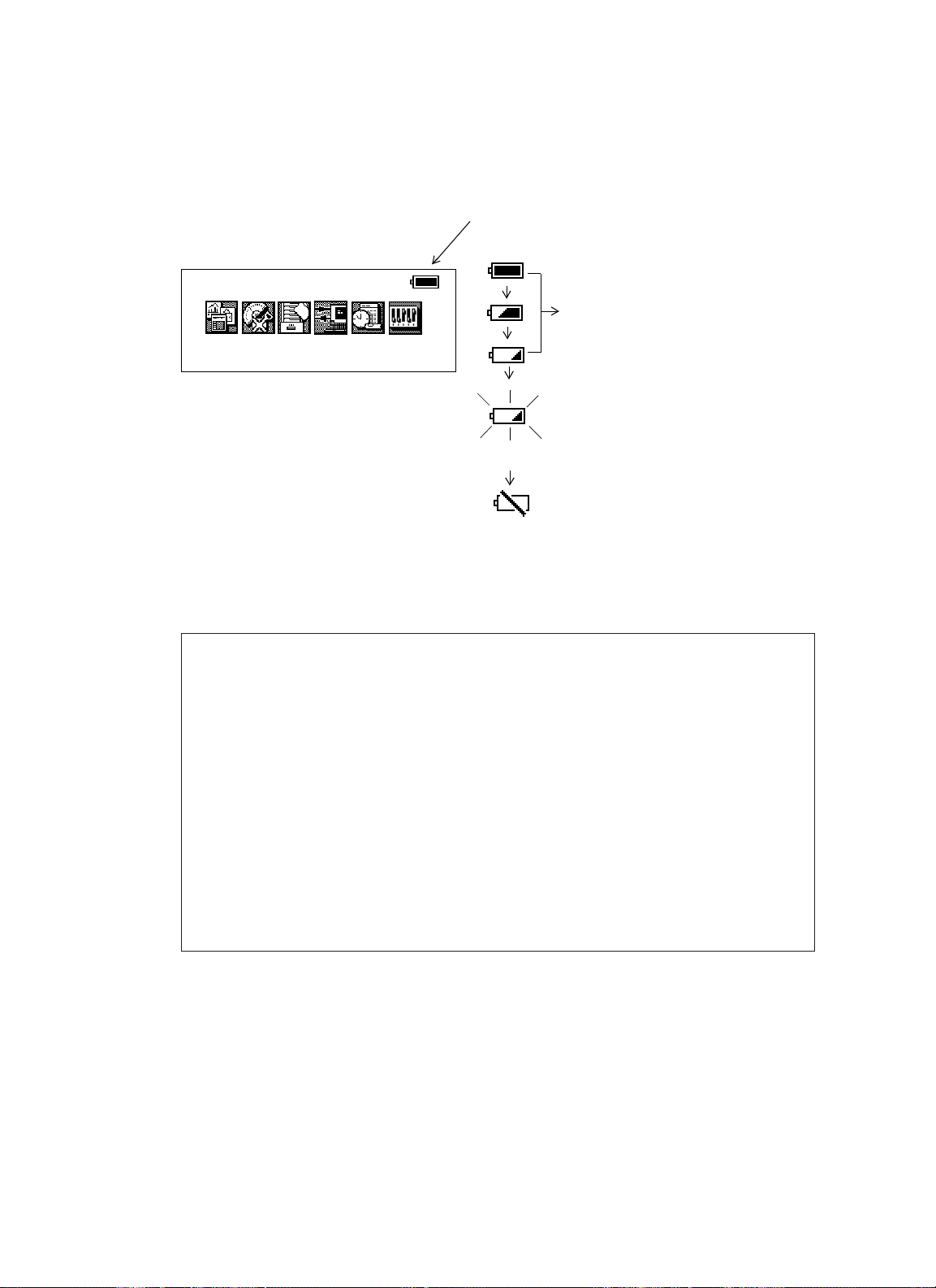
2.4 Battery Level Indicator
The battery power indicator shows the level of battery strength.
Indicates Battery Power Remaining
Measurement is possible.
The power is poor. The battery should
be recharged or replace
the battery.
(Angle measurement can only be possible, the auto-collimating and distance
measurement can not be possible.)
Measurement is impossible. Need to
recharge or replace the battery.
* Battery power remaining display is omitted in this manual.
Note:
1) The battery operating time will vary depending on the environmental conditions, such as
ambient temperature, charging time, and the number of times charging and discharging
the battery.
2)In low temperature (especially while the heater of display is working), the battery operating
time will shorten to one-half of normal temperature use.
3)The indicator for battery power remaining shows the power level during each measurement
mode. The condition indicated for the battery power remaining in the angle measurement mode
may not be adequate to measure a distance. Changing from angle mode to distance mode
during a poor battery condition may cause the EDM not to measure a distance. We recommend
that you check the battery condition before going into the field.
4)Also note, when changing from one measurement mode to another, the battery indicator
may not show a decrease or an increase immediately. The battery indicator system was
designed to show the general condition for the battery strength. It does not respond
instantly.
5)For more information on battery usage, refer to Chapter 13
“POWER SOURCE AND CHARGING”.
2002-07-10 15:30:40
Prog Std Mem Com
Adj
Para
Blinking
Page 31

2 PREPARATION FOR MEASUREMENT
2-5
2.5 Main Menu Icons
The main menu icons are as follows.
Select the menu by pressing soft keys ([F1]~[F6]).
PARAMETERS SETTING MODES
The PARAMETERS SETTING MODES are
stored in memory once the instrument is OFF.
(See Chapter 8 “PARAMETERS SETTING
MODE”.)
ADJUSTMENT MODES
Used for checking and adjustment.
• Systematic errors adjustment for compensation.
• Show compensation values of systematic errors of
instrument
• Set Date & Time
• Set instrument constant value
• Optic Axis for Auto-tracking (GPT-8000Aseries)
(See Chapter 9 “CHECK AND ADJUSTMENT”.)
COMMUNICATION MODES
• Set communication with external instrument
•Input/Output a data file
(See Chapter 7 “COMMUNICATION MODES”.)
MEMORY MANAGE MODES
• Display memory status
• Protect/Eras/Rename/Copy Files,
• Initialize a card or internal memory.
(See Chapter 6 “MEMORY MANAGE MODES” .)•2-6
STANDARD MEASUREMENT MODES
• Angle measurement
• Distance measurement
• Coordinate measurement
(See Chapter 4 “STANDARD MEASUREMENT MODE” .)
PROGRAM MODES (APPLICATION MEASUREMENT)
• Set a direction angle for horizontal orientation
• Retain Coordinate (STORE-NEZ)
• Remote elevation measurement
• Missing line measurement
• Line measurement
• External link for GPT-8000Aseries
• Off set measurement
(See Chapter 5 “PROGRAM MODES” .)
Page 32

2 PREPARATION FOR MEASUREMENT
2-6
2.6 Vertical and Horizontal Angle Tilt Correction
When the tilt sensors are activated, automatic correction of vertical and horizontal angle for mislevelment is displayed.
To ensure a precise angle measurement, tilt sensors must be turned on. The display can also be
used to fine level the instrument. If the (TILT OVER) display appears the instrument is out of automatic compensation range and must be leveled manually.
• GPT-8000A/8000 series compensates both the vertical angle and the horizontal angle
readings due to inclination of the standing axis in the X and Y directions.
• For more information about dual axis compensation, see Chapter “APPENDIX” “Dual Axis
Compensation”.
• The display of Vertical or Horizontal angle is unstable when instrument is on an unstable
stage or a windy day. You can turn off the auto tilt correction function of V/H angle in this case. To
set TILT correction mode ON/OFF, refer to next page or Chapter 8 “PARAMETERS SETTING
MODE”.
Rotate the leveling screws and level the
instrument.
After leveling (when each axis is within ±1'30"),
the display returns to the previous mode
automatically.
X,Y tilt correction range : within ±4'
Zenith
Zenith
Standing axis
Standing axis
Inclination of the stan di ng
axis in the Y dir ecti on
Inclination of the standing
axis in the X direction
Horizontal
W X
V
T
S
Q
P
D
O
When the instrument ti lted over correction
range.
U
R
|
Tru n nion axis
X:
Y:
X:00°00'00"
Y:00°00'00"
Page 33

2 PREPARATION FOR MEASUREMENT
2-7
• Setting Tilt Correction by Soft Key
Enable you to select tilt ON/OFF function on page 2.
The setting performed here will be memorized after powering OFF.
[Example] Setting X,Y Tilt ON
2.7 Compensation of Systematic Error of Instrument
1)Error of vertical axis (X,Y tilt sensor offset)
2) Collimation error
3) Error of vertical angle 0 datum
4) Error of horizontal axis
The above mentioned errors can be compensated by software, which calculated internally
according to each compensation value. Also these errors can be compensated by software collimating one side of the telescope that is carried out to delete the error by turning in normal and reverse
both sides of telescope so far.
•To adjust or reset the above compensation value, see Chapter 9 “CHECK AND ADJUSTMENT”.
• Enable you to stop this function, see Chapter 8 “PARAMETERS SETTING MODE” or
Chapter 9 “CHECK AND ADJUSTMENT”.
Operating procedure Option Display
1
Press [F6] key to get the function page 2.
V : 87°55'45"
HR: 180°44'12"
[F6]
2
Press [F5](TILT) key.
Current setting is displayed. *1
3
Press [F2](ON-2) key.
The displa y shows tilt correction valu e.
4
Press [F1] key.
The display returns previous mode.
*1) Pressing [F6](ESC) key, the display returns previous mode.
The tilt sensor setting will be stored in memory when the inst rument is turned OFF.
●
The tilt sensor option can also be changed in the Parameter Setting Modes. When you change the tilt
sensor option in the angle measurement mode, it will change in the Parameter Setting Modes and visa
verse.
[F5]
[F2]
[F1]
SD HD NEZ 0SET HOLD P1
REC HSET R/L V/% TILT P2
TILT ON (V)
ON-1 ON-2 OFF ESC
X:00° 00'00"
Y:00° 00'00"
↓
↓
Page 34

2 PREPARATION FOR MEASUREMENT
2-8
2.8 Resume Mode ON/OFF
The Resume mode will memorize the last display or mode when the power is turned OFF. When
the power is turned back ON, the last display or mode will be shown.
The Resume mode option only appears when the power is OFF.
2.9 How to Enter Numerals and Alphabet Letters
Alpha and numeric character key entry is simple and quick from the key board.
[Example] Renaming a file in the Memory Manager Modes.
Po wer sw it ch key OFF
Power off
Resume mode
OFF ON ESC
[F1] [F2]
Pressing [F1](OFF) key or [F2](ON) key, select the resume mode.
Operating procedure Option Display
Rename
Old name [TOPCON .DAT]
1
Press [F1](Alpha) key to be entering alphabet
letter mode.
2
Enter Alphabets. *1)
3
Press [F1](Num) key to be entering numeric
mode.
Type “H ”
Move cursor
Type “I”
Type “L”
Type “
”
Input “104”
[F1]
[9][9]
[F4]
[9][9][9]
[4][4][4]
[3][3][3]
[F1]
[1][0][4]
New name [
Alpha SPC ← →
Rename
Old name [TOPCON .DA
New name [HIL
Num SPC ← →
Rename
Old name [TOPCON .DAT]
New name [HIL
]
]
104 ]
T]
Alpha SPC ← →
4
Press [ENT] when complete.
*1) When the same alpha key is to be typed two or more times consecutively, press [F4](→) key between
characters. This moves the cursor to the right .
*2) Ext ens i ons can not be changed .
[ENT]
Page 35

2 PREPARATION FOR MEASUREMENT
2-9
2.10 Memory Card
How to insert a memory card
1) Pull the card cover lever to open the
card cover.
2) Insert a memory card until the card
guide is up.
3) Close the card cover.
How to extract a memory card
1) Pull the card cover lever to open the
card cover.
2) Pull down the card guide.
3) Extract the memory card.
Card cover lever
Card guide
Memory card
Card guide
Page 36

2 PREPARATION FOR MEASUREMENT
2-10
2.11 Inclination of Prism and Measuring Error
(GPT-8000A series)
For the best results, aim or point prisms in the direction of the GPT-8000Aseries so that maximum
signal can be returned to the instrument. Sighting prism obliquely because of inclined settings, may
result in measuring errors. These errors will be proportional to the misalignment as showing in following graphs. The more misalignment of the prism, the more error in measurement. Measured data
can be different according to the prism constant value. This can occur when a prism is moving. Pinpole prism set L1 (for one-person surveying) and pin-pole prism holder L1 (for fixed point observation) are designed to minimize measuring error in such case. Make the best use of them. In case
you are forced to use the normal prism in inclined state because there is no other way possible, we
recommend to use switching holder, prism constant value (0 or 30mm), and set to 30mm
(Compensation value of -30mm).
Prism constant value : 0mm
Prism
Inclined angle
Measuring
point
Instrument
point
Prism constant value : 30mm
Inclined angle
Page 37

2 PREPARATION FOR MEASUREMENT
2-11
● Prism type-2 (Normal prism)
(Example)
In case Prism constant value (C) = 0mm, Prism inclination = 20°, Measuring distance = 100m by
Prism type-2 :
• Distance error is :
From the graph prism type-2, the distance error shows in increasing range quantity 2.5mm along
curved line of C=0 when prism inclination is 20°.
• Angle error is :
From the graph prism type-2, along curved line of C=0 with prism inclination of 20°, find angle error
quantity (14.2mm) and calculate angle error by the following formula.
Distance Measuring error
6
5
4
Increasing
distance
3
range
( mm )
2
1
0
-1
0
Inclined angle (degree)
● Prism t ype - 3 or 5 (Prism unit A2 /A3)
Distance Measuring error
4
3
2
Increasing
di
stance
range
1
( mm )
0
-1
0
Inclined angle (degree)
C=0
10
C=0
10 20 30
20
C=20
C=30
C=30
C=40
30
Angle error
range
( mm )
22
18
14
Angle error
range
( mm )
-2
12
8
4
0
-4
0
6
2
0
0
Angle measuring error
10
Inclined angle (degree)
Angle measuring error
C=0
C=30
10
Inclined angle (degree)
20
20 30
-1
Angleerror range
Angle error =
tan
------------------------------------------------------
Measuring dis cetan
C=0
C=30
C=40
30
C=20
-1
=
tan
--------------------
100x10
=29″
14.2
3
Page 38

3 AUTOMA TIC TRACKING / AUTOMATIC COLLIMA TION (GPT-8000A series)
3-1
3.1 Automatic Tracking
Measuring the moving target in automatic tracking mode.
• It is possible to perform auto-tracking only in prism mode. When switched to the automatic
tracking mode, it becomes prism mode from NP mode automatically. Moreover, after the end of an
automatic tracking does not return to Non-prism mode.
• The Coarse (10mm) mode is used for the moving target.
• Use a keyboard on the eyepiece side. When the keyboard on the opposition side is used an
error will be displayed to protect a worker from the radiation of the laser.
3 AUTOMATIC TRACKING / AUTOMATIC COLLIMATON
(GPT-8000A series)
WARNING
WARNING
Cause e ye injur y or blindness.
●
Do not st a re int o beam.
CAUTION
CAUTION
Let the laser bea m rea ch the aimed object or the target without an ybody else in the laser beam path. In
●
case you operate laser beam open, avoid radiating laser beam to the height of man's head. It is quite
possibl e for the beam to ent er into one's e yes, and it is possible to lose visual sight temporarily, and lose
one's caution and a w are ness of other dangers - avoid glaring beam.( GPT-8000A series)
Operating procedure Option Displa y
Manually collimate the target prism using V/H
1
jog/shuttle.
Press the star [ ] key to show the star key
2
options.
Press the [F1] key. The mode will be
3
automatic tracking mode.
The instrume nt searches the prism and t racks
automatically.
[]
[F1]
V : 87°55'45"
HR: 180°44'12"
SD HD NEZ 0SET HOLD P1↓
V : 87°55'45"
HR: 180°44'12"
SD HD NEZ 0SET HOLD P1↓
2002-07-07 14:30: 40
↓
1
NP/P
Page 39

3 AUTOMA TIC TRACKING / AUTOMATIC COLLIMA TION (GPT-8000A series)
3-2
Choose measuring modes by pressing the
4
soft keys.
Measuring starts.
Sample: Horizontal distance measuring
If the target prism is lost during auto tracking status, the instrument will automatically cha nge to Waiting
●
status and symbol mark will be switched. If the target is found during Waiti ng status, tracking resumes,
and if not, status changes to Searching status. When the target prism is found, tracking will resume.
[F2]
V : 90°10'20"
HR: 120°30'40" PS M 0.0
HD: < PPM 0.0
VD: (m) *c.R
MEAS MODE VH SD NEZ P1↓
Automatic tracking
Tracking
status
Normal
Star key
mode
F1
mode
The target prism is lost
Waiting status
The target prism is not found
for some time
Searching status
us
The following symbol marks are indicated at the right side of the display.
●
In all these status, laser beam is emitting.
Tracking status
Waiting status
The target prism
is found
Searching stat
Auto trackin g status sometimes can be uns tab le f or a few seconds after the optical path is disturbed .
●
If the center of reticle and the center of the prism is not coincided, you should adjust optical axis for
●
auto-tracking, refer to chapter 9"Check and adjustment".
In the not suitable operating condit i on in such the atmospheric co ndition i s not good by the heat
●
shimmer, or other bad weather condition, in the long distance of the auto-tracking limit, can be
happened not certain tracking or not tracking at the center of the prism.
Page 40

3 AUTOMA TIC TRACKING / AUTOMATIC COLLIMA TION (GPT-8000A series)
3-3
3.2 Automatic Collimation
The function enables to collimate automatically so that the instrument searches for the center of the
prism when the telescopic is aimed a prism roughly.
Use this mode for the object which is stable.
•You can select Fine or Course mode for the distance measurement in auto-collimation.
Operating procedure Option Display
Manually collimate the target prism roughly
1
using V/H jog/shuttle.
V : 87°55'45"
HR: 180°44'12"
SD HD NEZ 0SET HOLD P1↓
Press the star [ ] key.
2
3
Press the [F2] key.
The instrume nt be gins to collimate When it
searches the prism.
4
Choose measuring modes by pressing the
soft keys.
Measuring starts.
Sample: Horizontal distance measuring
In case the instrument could not find the prism during auto-collimating, the auto-collimating mode
●
returns to normal mode after displaying the mark as follows.
Instrument could not f ind the pris
If any key is pressed during auto-collimating, the auto-collimating mode returns to normal mode.
●
After auto-collimating is finished, the instrument does not track the prism even if the prism is moved.
●
The auto-tracking can be done correctly in the time of shaking prism, or in bad weather conditio n is not
●
good by the heat shimmer. The above caution mark will be displayed after 10 seconds and the autotracking will be finished.
[]
[F2]
[F2]
m
V : 87°55'45"
HR: 180°44'12"
SD HD NEZ 0SET HOLD P1↓
V : 90°10'20"
HR: 120°30'40" PS M 0.0
HD: < PPM 0.0
VD: (m) *c.R
MEAS MODE VH SD NEZ P1↓
2002-07-07 14:30: 40
NP/P
↓
1
Page 41

3 AUTOMA TIC TRACKING / AUTOMATIC COLLIMA TION (GPT-8000A series)
3-4
3.3 Range of Laser for Auto-tracking and Auto-collimating
The range of laser at the long distance is within ±30' as shown in following. So you had better collimate the prism so that the prism may be located within this range of laser in the first step. As for it,
rapid automatic collimating and automatic tracking becomes possible. If the target prism is out of this
range, time for searching mode will be necessary.
Field of view
about ±30'
Range of laser
about ±30'
Page 42

3 AUTOMA TIC TRACKING / AUTOMATIC COLLIMA TION (GPT-8000A series)
3-5
3.4 Setting Parameters for Auto-Tracking
A proper setting for each parameter are necessary for custom use.
The setting of the parameters can be done in the star key mode.
3.4.1 Setting Items
1) Search Patterns
The search pattern is the rotating method of telescope and instrument to find the target prism in
search mode. Search pattern includes the following 2 ways that can be selected.
1) Things like heat haze might interfere with the tracking system in the long distance, near
limit of auto tracking range, in search mode.
2) Reaction by rotating of instrument in search mode is serious. Be sure of each
connection part of the tribrach or tripod are firmly.
Items Selecting item Contents
SEARCH
PAT T E R N
SEARCH
RANGE
WAIT TIME 0:00 to1:00:00
TRACKING
SPEED
REFRECTOR
TYPE
PATTERN 1 The search r ange is the area to searched for the prism b y rot ating
PATTERN 2
V:0° to 90°
H:0° to180°
(1sec. step)
HOLD
SURVEY Select your purpose.
MACHINE
CONTROL
PRISM The type of the refre ctor can be selected.
REFRECTOR
TA P E
the telescope and body in searching.
The search r ange is the area to searched for the prism by rot ating
the telescope and body in searching. The SEARCH range is
decided from the point where the prism lost, and the values will be
set to plus and minus directions in horizontal and ve rtical. Also it is
enable to set each search pattern separately.
The time the prism is lost before GPT-8000A series starts the
searching. If the mode is set to [HOLD], mode will not change to
searching.
This pattern can be selected to search the prism at the point where the prism is lost.
Instrument searches in up down direction gradually from the point where the prism is lost.
PATTERN 1
PATTERN 2
The searching is arranged to 2 times until the prism is found.
The auto tracking mode changes to manual mode when the refrector could not found out
within 2 times searching, and returns to the point where the refrector is lost.
This pattern can be selected to search for the prism. The search pattern tries to locate the
prism in a very short time.
The searching is arranged to 2 times until the refrector is found.
The auto tracking mode changes to manual mode when the refrector could not found out
within 2 times searching, and returns to the point where the refrector is lost
Page 43

3 AUTOMA TIC TRACKING / AUTOMATIC COLLIMA TION (GPT-8000A series)
3-6
2) Search Range
The search range is the area to searched for the prism by rotating the telescope and body in
Searching. The Search range is decided from the point where the prism lost, and the values will
be set to plus and minus directions in horizontal and vertical.
Select search pattern first, and set the search range to the selected search pattern. Also it is
enable to set each search pattern separately.
[Example] SEARCH RANGE: 10º in horizontal, 5º in vertical
Setting Search range requires consideration. The items to think about: optical path interrupted by
other objects; collimated point from GPT-8000Aseries to prism is shifted after Turning and
Searching Command; possible other prisms, targets, or other objects to interfere with tracking the
desired prism; and many other examples all play a role in determining the search range.
Note: This search range is only for auto-tracking function. The search range of auto-collimating is
fixed as ±5••• in both directions horizontal and vertical.
3) Wait Time
The time the prism is lost before GPT-8000Aseries starts the searching. Setting time is 1second
step maximum 60 minutes.
If the mode is set to [HOLD], mode will not change to searching.
4) Tracking Speed
The tracking accuracy (aiming accuracy) shall be determined in the best condition by the relationship of moving speed of the prism and the distance between GPT-8000Aseries and the prism at
the field. Since the tracking speed represents the rotating speed of GPT-8000Aseries, if the
prism’s traveling speed is high, yet the distance of the prism is far from the GPT-8000Aseries, the
tracking speed can be low.
5) Reflector type
You can choose a reflector type according to reflective objects such as Prism-2 or reflector tape.
This setting will reduce incorrect tracking.
Search range
+5°
10°
Point w here prism lost
-10° +10°
20°
-5°
In case requiring auto aiming in high accuracy to the prism which is still.
●
Suitable for fixed point observation, management of landslides, surveying
SURVEY
MACHINE
CONTROL
●
displa cement of dam.
When beginning auto-tracking, the instrument needs to collimate stable prism.
●
Suitable for controlling of construction machinery or real time surveying of variety
●
traveling objects.
When beginning auto-tracking, the instrument can track a prism, even if the prism is
●
moving.
Page 44

3 AUTOMA TIC TRACKING / AUTOMATIC COLLIMA TION (GPT-8000A series)
3-7
3.4.2 How to set the parameters
Sample setting: Set TRACKING SPEED to [MACHINE CONTROL]
Operating procedure Option Display
Press the star [ ] key to be in star key
1
mode.
[]
2002-07-07 14:30: 40
↓
1
NP/P
Press the [F3] key to select the setting
2
parameters for auto-tracking.
Press the [F6](P1↓) key to get the menu on
3
page 2.
Press the [F1](TRK SPEED) key.
4
Press the [F6](↓) key to sel ect [MAC HINE
5
CONTROL].
6
Press the [ENT] key to decide.
[F3]
[F6]
[F1]
[F6]
[ENT]
F1:SEARCH PATTERN
F2:SEARCH RANGE
F3:WAIT TIME
P1↓
F1:TRK SPEED
F2:REF LE CTOR TYPE
P1↓
TRACKING SPEED
SURVEY
↑
TRACKING SPEED
MACHINE
↑
CONTROL
↓
↓
Page 45

4 STANDARD MEASUREMENT MODE
4-1
4.1 Angle Measurement
4.1.1 Measuring Horizontal Angle Right and Vertical Angle
Make sure the mode is in Angle measurement.
4 STANDARD MEASUREMENT MODE
Operating procedure Operation Display
Collimate the 1st target (A).
1
Collimate
A
V : 87°55'45"
HR: 180°44'12"
SD HD NEZ 0SET HOLD P1
Set horizontal angle of target A at 0° 00' 00".
2
Press [F4](0 set) key and [F6](SET) ke y.
3 Collimate the 2nd target (B).
The required H/V angle to target B will be
displayed.
[F4]
[F6]
Collimate
B
H-0SET
HR: 00°00'00"
ESC SET
V : 87°55'4 5"
HR: 00°00'00"
SD HD NEZ 0SET HOLD P1
V : 87°55'4 5"
HR: 123°45'50"
SD HD NEZ 0SET HOLD P1
Reference : How to Collimate
1Point the telescope toward the light. Turn the diopter ring and adjust the diopter so that the cross
hairs are clearly observed.
(Turn the
Aim the targ et at t he pea k of the t riangle mark of the sighting collimator. Al l ow a certain space
2
between the sighting collimator and yourself for collimating.
Focus the target with the focusing knob.
3
diopter ring toward you first and then backward to focus.)
↓
↓
↓
*If parallax is created between the cross
hairs and the target when viewing
vertically or horizontally while looking
into the telescope, focusing is incorrect
or diopter adju stm ent i s poor.
This adversely affects precision in
measurement or survey. Eliminate the
parallax b y carefully focusing and using
diopter adjustment.
Åá
Åá
Focusing knob
Teles cope eyepiece (Diopter ri )
Åá
Åá
Page 46

4 STANDARD MEASUREMENT MODE
4-2
4.1.2 Switching Horizontal Angle Right/Left
Make sure the mode is Angle measurement.
4.1.3 Measuring from the Required Horizontal Angle
1) Setting by Holding the Angle
Make sure the mode is angle measurement.
Operating procedure Operation Display
1
Press [F6](↓)key to get the function as on
page 2.
[F6]
Press [F3](R/L) key.
2
The mode Horizontal angle Right (HR)
switches to (HL) mode.
3
Measure as HR mode.
Every time pressing [F2](R/L) key is pressed, HR/HL mode switches.
●
● HR/HL switching can be turned OFF. Refer to Chapter 8 “PARAMETERS SETTING MODE” .
[F3]
V : 87°55'45"
HR: 120°30'40"
SD HD NEZ 0SET HOLD P1
TURN HSET R/L V/% TILT P2
V : 87°55'45"
HL: 239°29'15" PSM 0.0
PPM 0.0
(m) *F.R
TURN HSET R/L V/% TILT P2
↓
↓
↓
Operating procedure Operation Display
1
Set the req uir e d horizontal angle, using
Horizontal jog/shuttle.
P1
Press [F5](HOLD) key.
2
Collimate the target.*1)
3
4
Press [F6](REL ) k ey to finish ho l di ng the
horizontal angle.
The display turns back to normal angle
measurement mode.
*1)To return to the previous mode, press [F1](ESC) key.
Display
angle
[F5]
Collimate
[F6]
V : 90°10'20"
HR: 70°20'30"
SD HD NEZ 0SET HOLD P1
Holding
HR: 70°20'30"
ESC REL
V : 90°10'20"
HR: 70°20'30"
SD HD NEZ 0SET HOLD
↓
↓
Page 47

4 STANDARD MEASUREMENT MODE
4-3
2) Setting a Horizontal Angle from the Keys
Make sure the mode is Angle measurement.
4.1.4 Vertical Angle Percent Grade(%) Mode
Make sure the mode is Angle measurement.
Operating procedure Operation Display
Collimate the target.
1
2
Press [F6](↓) key to get the funct ion as on
page 2, and pres s [F2] (HSET) key.
Input the required horizontal angle.
3
*1)
For example:70
Press [ ENT] key. *2)
4
20'30"
°
When completed, norm al measur ing from the
required Horizontal angl e is poss ible.
Collimate
[F6]
[F2]
Input
value
[ENT]
V : 90°10'2 0"
HR: 120°30'40"
SD HD NEZ 0SET HOLD P1
TURN HSET R/L V/% TILT P2
H-SET
HR:
H-SET
HR:70.203
EXIT BS
V : 90°10 '20"
HR: 70°20'30"
SD HD NEZ 0SET HOLD P1
↓
↓
↓
*1)To revise wrong value, move cursor with [F6](BS) key, or input from the beginning by [F1](EXIT) key to
correct value.
*2)With wrong input value (for example 70'), setting will not be completed. Input again from step
.
3
Operating procedure Operation Display
1
Press [F6](↓) key to get the function as on
page 2.
[F6]
2
Press [F4](V/%) key. *1)
*1) Every time pressing the [F4](V/%) key, the display mode switches.
[F4]
V : 90°10'20"
HR: 120°30'40"
SD HD NEZ 0SET HOLD P1
TURN HSET R/L V/% TILT P2
V%: -0.30 %
HR: 120°30'40"
TURN HSET R/L V/% TILT P
↓
↓
↓
Page 48

4 STANDARD MEASUREMENT MODE
4-4
4.1.5 Automatic Rotation to a Required Horizontal and Vertical
Absolute Angle
The GPT-8000A/8000 series can be rotated to a required horizontal and vertical absolute
angle by direct key input.
Example: Both vertical and horizontal angle
Operating procedure Operation Display
Press the [F6](↓) key to display the second
1
soft ke y page.
Press the [F1](TURN) key.
2
Press the [F3] key.
3
4
Input the vertical angle to be rotated and
press [ENT] key. *1)
For example : 93
5
Input the horizontal angle to be rotated, and
press [ENT] key.
For example : 160
The instru ment will start to rotate. *2)
When the i nstrument has fin ishe d rotatin g * 3),
the instrument will return to the previous
mode.
10'40"
°
20'10"
°
[F6]
[F1]
[F3]
V angle
[ENT]
H angle
[ENT]
160
V : 87°55'45"
HR: 120°30'40"
SD HD NEZ 0SET HOLD P1
TURN HSET R/L V/% TILT P2
TURN(Absolute)
F1. V angle
F2. H angle
F3. V/H angle
TURN(Absolute)
V :
HR:
EXIT BS
TURN(Absolute)
V : 93°10'10"
HR:
°20'10"
<Rotating...>
↓
↓
*1) Sett ing ra nge for rotation is ;
0
°00' 00 "≤ HR ≤+359°59' 59"
0
°00' 00 "≤ V ≤ +359°59' 59"
*2) Press any key except power ke y to stop rotating in emerge ncy duri ng operation.
*3)You can select a accuracy of the actual stopping angular positions . Refer to Chapter 8 “PARA METERS
SETTING MODE” .
Page 49

4 STANDARD MEASUREMENT MODE
4-5
4.2 Distance Measurement
Note:
Those distance shorter than 2.5m will not be displayed in Non-prism mode.
•Prism mode and Non-prism mode
In GPT-8000A/8000 series, the distance measurement will be done using invisible pulse laser beam
emitted from pulse laser diode. You can select measurement mode between Prism mode which collimating a prism and Non-prism mode that is collimating a target object except prism.
Non-prism mode enables all distance measurements such Distance measurement, Coordinate measurement and Offset measurement. To switch over Prism mode to Non-prism mode or contrary, press
the [F5] key in star key ( ) mode. [NP] of Non-prism mode indicator will blink at the right corner of the
display in Non-prism mode measurement and Non-prism constant value (NPM) will be displayed.
Changing mode shall be done before measurement. If happened collimating the near distance prism
in Non-prism mode, measurement will not be done because of too much light.
4.2.1 Setting of the Atmospheric Correction
When setting the atmospheric correction, obtain the correction value by measuring the temperature
and pressure.
Setting the atmospheric correction is in the STAR key () mode, see Chapter 11 “ SETTING ATMOSPHERIC CORRECTION” .
4.2.2 Setting of the Correction for Prism Constant / Non-prism Constant
Topcon's prism constant value is 0. Set correction for prism at 0. If the prism is of another manufacture, the appropriate constant shall be set beforehand.
Setting the prism constant value is in the STAR key ( ) mode, see Chapter 10 “SETTING THE PRISM
/ NON-PRISM CONSTANT VALUE” .
Note:
Confirm that Non-prism correction value is set at zero before measurement target such as a wall in
Non-prism mode.
Example
Distance measurement mode
V : 90 10'20"5 NP
HR: 120 30'40"5 NPM 0.0
Non-prism mode indicator
Non-prism const an t valu
HD: PPM 0.0
VD: (m) F.R
MEAS MODE VH SD NEZ P1
↓
Page 50

4 STANDARD MEASUREMENT MODE
4-6
4.2.3 Distance Measurement (Continuous Measurement)
Make sure the mode displays angle measurement.
Operating procedure Operation Display
Collimate the center of prism.
1
Press [F1](SD) key or [F2]( HD )key.
2
*1), 2)
[Example] Horizontal distance mode
[F2]
V : 90°10'20"
HR: 120°30'40"
SD HD NEZ 0SET HOLD P1
V : 90°10'20"
HR: 120°30'40" PSM 0.0
HD: < PPM 0.0
VD: (m) *F.R
MEAS MODE VH SD NEZ P1
↓
↓
The result are shown *3) to *6)
*1)
The following characters will be shown on the 4th line right hand corner of the display to
V : 90°10'20"
HR: 120°30'40" PSM 0.0
HD: 716.661 PPM 0.0
VD: 4.001 (m) *F.R
MEAS MODE VH SD NEZ P
represent measurement mode.
: Fine meas. mode, C: Coarse (1mm) meas. mode, c: Coarse (10mm) m eas. mod e.
F
: Continuous (Repeat) meas. mode , S: Single meas. mode, N: N time meas. mode
R
*2) When EDM is working, the "* " mark appears in the display.
*3) The result is shown with b uzzer sound.
*4) Measurement may repeat automatically if the result is affected by shimmer etc..
*5) To change single measuring, press [F1](MEAS) key.
*6) To return to the angle measurement mode, press [F3](VH) key.
1
↓
Page 51

4 STANDARD MEASUREMENT MODE
4-7
4.2.4 Distance Measurement (Single/N-times Measurement)
When presetting the number of times, the instrument measures the distance as the setting times and
the average distance will be displayed. When presetting the number of times as 1, it does not display
the average distance, because of single measurement. It has been set at single measurement at factory.
1) Setting the number of times
Confirm the angle measurement mode.
2) Measuring Method
Confirm the angle measurement mode.
Operating procedure Operation Display
1
Press [F1](SD) or [F2](HD) key.
V : 90°10'20"
HR: 120°30'40"
SD HD NEZ 0SET HOLD P1
↓
Press [F6](↓) key to get the function page as
2
2.
Press [F3](MEAN) key.
3
4
Input the setting the number of times , and
press [ENT] ke y. *1)
[Example] 4 times
N-times measurement starts.
Operating procedure Operation Display
1
Collimate the center of the prism.
2
Select the measurement mode by pressing
[F1](SD) or [F2](HD) key.
Example: Horizontal distance
N-times measurement starts.
[F2]
[F6]
[F3]
1
[F4][ENT]
Collimate
[F2]
V : 90°10'20"
HR: 120°30'40" PSM 0.0
HD: PPM 0.0
VD: (m) F.R
MEAS MODE VH SD NEZ P1
REC SO MEAN m/ft P2
Average times
N:0
EXIT BS
V : 90°10'20"
HR: 120°30'40" PSM 0.0
HD: < PPM 0.0
VD: (m) *F.N
REC SO MEAN m/ft P2
V : 90°10'20"
HR: 120°30'40"
SD HD NEZ 0SET HOLD P1
V : 90°10'20"
HR: 120°30'40" PSM 0.0
HD: PPM 0.0
VD: (m) F.N
MEAS MODE VH SD NEZ P
↓
↓
↓
↓
↓
Page 52

4 STANDARD MEASUREMENT MODE
4-8
V : 90°10'20"
HR: 120°30'40" PSM 0.0
HD: 54.321 PPM 0.0
VD: 1.234 (m) *F.N
MEAS MODE VH SD NEZ P1
The average value is displayed f ollowing with
buzzer sound and “ * ” mark disappears.
V : 90°10'20"
HR: 120°30'40" PSM 0.0
HD: 54.321 PPM 0.0
VD: 1.234 (m) F.
MEAS MODE VH SD NEZ
Press [F1](MEAS) key for re-measuring after the measurement in held.
●
● To return to the continuous measuring , press [F1](MEAS) key twice.
● To retur n to the angle measuring mode , press [F3](VH) key.
P1
↓
↓
Page 53

4 STANDARD MEASUREMENT MODE
4-9
4.2.5 Fine / Coarse Measuring Mode
•Fine mode : This is a normal distance measuring mode.
Measurement time 0.2mm mode: approx.3 seconds
1 mm mode : approx.1.2 seconds
The unit to be displayed is 0.2mm or 1mm. (0.001ft or 0.005ft)
•Coarse mode : This mode measures in shorter time than in fine mode.
(1mm) Use this mode for the objects which may be slightly unstable.
Measurement time : approx. 0.5 seconds
The unit to be displayed is 1mm. (0.005ft)
•Coarse mode : This mode measures in shorter time than in coarse(1mm) mode.
(10mm) Use this mode for stake out measurement. It is very useful when
tailing the moving object or carrying out stake-out work.
Measurement time : approx. 0.3 seconds
The unit to be displayed is 10mm. (0.02ft)
Operating procedure Operation Display
Collimate the center of prism.
1
Select the measurement mode by pressing
2
[F1](SD) or [F2](HD) key.
Example: Horizontal distance
Measuring starts.
3
Press [F2](M ODE) k e y, the mode changes to
Coarse mode.
Press [F2](MODE) key again, the mode
changes to Tracking mode. *1)
Collimate
[F2]
1
[F2]
[F2]
V: 90°10'20"
HR: 120°30'40"
SD HD NEZ 0SET HOLD P1
V : 90°10'20"
HR: 120°30'40" PSM 0.0
HD: < PPM 0.0
VD: (m) *F.R
MEAS MODE VH SD NEZ P1
V : 90°10'20"
HR: 120°30'40" PSM 0.0
HD: PPM 0.0
VD: (m) c.R
MEAS MODE VH SD NEZ P
↓
↓
↓
*1) Every time the [F2](MODE) key is pressed, the mode will change as demonstrated.
The mode is indicated in the alphabet (F, C, c) on the bottom right of the screen.
F: Fine mode, C: Coarse 1mm mode, c: Coarse 10mm mode
Page 54

4 STANDARD MEASUREMENT MODE
4-10
4.2.6 Stake Out (S-O)
The stake out distance is the difference between the measured distance and the preset distance.
Display value = Measured distance -Standard (Preset) distance
The value on the display is the distance in which the rod person must move toward or away from the
instrument. Aminus (-) sign appearing before the stake out distance indicates that the rod person
would move away from the instrument to reach the stake out distance. If the stake out distance is
displayed with no sign, indicating positive (+), the rod person toward the instrument to reach the
stake out distance.
• Stake out operation can be accomplished in any distance measuring mode, horizontal distance
(HD), relative elevation (VD), or slope distance (SD).
[Example: Relative elevation]
Operating procedure Operation Display
1
Press [F6 ](P1 ) k ey in the distance meas uri ng
mode to get the function as in page 2.
Press [F2](S-O) key and press [ENT] key.
2
Enter the rela ti v e elevat ion for stak e out, and
3
press [ENT] key.
The measurin g starts .
4
Collimate the target (Prism).
[F6]
[F2]
[ENT]
Enter
value
[ENT]
2
V : 90°10'20"
HR: 120°30'40" PSM 0.0
HD: PPM 0.0
VD: (m) F.R
MEAS MODE VH SD NEZ P1
TURN SO MEAN m/ft P2↓
SO
HD : 0.000
VD :
EXIT BS
V : 90°10'20"
HR : 120°30'40" PSM 0.0
HD : < PPM 0.0
dVD : (m) *F.R
TURN SO MEAN m/ft P2
↓
↓
The difference between the measured
distance and the standard distance is
displayed.
To retu rn to normal dist ance measurement mode, reset the st and ard distance to “ 0 ” or turn the pow er
●
switch off (Resume mode: OFF) once.
V : 90°10'20"
HR: 120°30'40" PSM 0.0
HD: 12.345 PPM 0.0
dVD: 0.09 (m) *F.R
TURN SO MEAN m/ft P
↓
Page 55

4 STANDARD MEASUREMENT MODE
4-11
4.3.1 Setting Coordinate Values of Occupied Point
The occupied point coordinates (NEZ) can be preset in the GPT-8000A/8000 Series to calculate the
unknown point coordinates. It is possible to retain the occupied coordinates in memory once the
power is turned OFF if the (NEZ mem) is ON in the Parameter Setting Modes. IF (NEZ mem) is OFF
in the Parameter Setting Modes, the occupied coordinates will be retained only if you choose
(Resume ON) when shutting the power OFF.
For instructions on how to select NEZ memory ON/OFF, refer to Chapter 8 “PARAMETERS
SETTING MODE”.
n
Inst.PointC
Origin(0,0,0)
Confirm the angle measurement mode .
Operating procedure Operation Display
1
Press [F3](NEZ) key.
press [F6](↓) key to get the function as on
2
page 2.
3
Press [F5](SET) key.
The previous data will be shown.
N
[F3]
[F6]
[F5]
Prism (n,e,z)
z
E
e
V : 90°10'20"
HR: 120°30'40"
SD HD NEZ 0SET HOLD P1
N : <
E : PSM 0.0
Z : PPM 0.0
(m) *F.R
MEAS MODE VH SD HD P1
TURN HT MEAN m/ft SET P2
Setting occ. point
N : 12345.6700
E : 12.3400
Z : 10.2300
EXIT BS
↓
↓
↓
Page 56

4 STANDARD MEASUREMENT MODE
4-12
Input new data and press [ENT] key. *1)
4
Measuring starts.
*1)To cancel the setting, press [F1](EXIT) key.
N coord.
[ENT]
E coord.
[ENT]
Z coord.
[ENT]
Setting occ. point
N : 0.0000
E : 0.0000
Z : 0.0000
EXIT BS
Complete
N : <
E : PSM 0.0
Z : PPM 0.0
(m)
TURN HT MEAN m/ft SET P2
*F.R
↓
Page 57

4 STANDARD MEASUREMENT MODE
4-13
4.3.2 Setting of the Instrument Height / Prism Height
The instrument height and prism height are used to compute the ground elevation of the unknown
point. If the option to store NEZ is (on), the instrument and prism heights will be stored in memory
when power is turned off.
Confirm the angle measurement mode.
Operating procedure Operation Display
V : 90°10'20"
HR: 120°30'40"
SD HD NEZ 0SET HOLD P1
Press [F3](NEZ) key.
1
Press [F6](↓) key from the coordinate
2
measurement mode to get the function as in
page 2.
Press [F2](HT) key to type in the instrument
3
and prism height .
Previous data will be shown.
Input instrument height, and press [ENT]
4
key.*1)
5
Input prism height, and press [ENT] key.
The display returns to coor di nate measuring
mode.
Prism HT
[F3]
[F6]
[F2]
Inst. HT
[ENT]
[ENT]
N :
E : PSM 0.0
Z : PPM 0.0
(m) *F.R
MEAS MODE VH SD HD P1
TURN HT MEAN m/ft SET P2↓
Inst. Ht : 1.230 m
R. Ht : 1.340 m
EXIT BS
N :
E : PSM 0.0
Z : PPM 0.0
(m) *F.R
TURN
HT MEAN m/ft SET
↓
↓
↓
*1)To cancel the setting, press [F1](EXIT) key.
Page 58

4 STANDARD MEASUREMENT MODE
4-14
4.3.3 Execution of Coordinate Measuring
Measure the coordinates by entering the instrument height and prism height, coordinates of
unknown point will be measured directly.
• When setting coordinate values of occupied point, see Section 4.3.1“Setting Coordinate Values
of Occupied Point” .
• When setting the instrument height and prism height, see Section 4.3.2“Setting of the
Instrument Height / Prism Height” .
• The coordinates of the unknown point are calculated as shown below and displayed:
Coordinates of occupied point : (N 0 , E 0 , Z 0)
Instrument height : Inst.h
Prism height : R.h
Vertical distance (Relative elevation) : z
Coordinates of the center of the prism,
originated from the center point of the instrument : (n,e,z)
Coordinates of unknown point : (N 1 , E 1 , Z 1 )
N 1 = N 0 + n
E 1 = E 0 + e
Z 1 = Z 0 + Inst.h + z - P.h
Coordinates of the center of the prism, originated from the center point of the instrument (n,e,z)
Center point of the instrument
(No, Eo, Zo + Inst.h)
Occupied point (No, Eo, Zo)
Origin (o, o, o)
Confirm t h e angle measurement mode.
Operating procedure Operation Display
1
Set coordin at e s v alues of occupi e d po i nt and
instrument/prism height. *1)
Set the dire cti o n angle of known poi nt A. *2)
2
3
Collimate target B.
4
Press [F3](NEZ) key.*3)
Measuring starts.
Unknown point
*F.R
1, E1, Z1)
(N
Set
direction
angle
Collimate
[F3]
V : 90°10'20"
HR: 120°30'40"
SD HD NEZ 0SET HOLD P1
N : <
E : PSM 0.0
Z : PPM 0.0
(m)
MEAS MODE VH SD HD P1
↓
↓
Page 59

4 STANDARD MEASUREMENT MODE
4-15
The result will be shown.
N : 12345.6789
E : -12345.6789 PSM 0.0
Z : 10.1234 PPM 0.0
(m) *F.R
MEAS M ODE VH SD HD
*1) In case the coordinate of instrument point is not entered, (0,0,0) will be used as the default for the
instrument point.
The instrument height will be calculated as 0 when the instrument height is not entered.
*2) The prism heig ht will be calculated as 0 when the prism height is not set.
*3) Refer to Section 4.1.3“Measuring from the Required Horizontal Angle”or Section 4.1.3“Measuring from
the Required Horizo ntal Angle”
*4) Pressing [F1](MEAS) key, the measurement mode (Continuous measuring/ N-time measuring)
changes.
Pressing [F 2](MODE) ke y, the measurement mode (FINE/ C OARSE(1mm)/ C O ARSE(1 0 mm )) changes.
● To return to the normal angle or distance measuring mode, pre ss [F6](P2
) key to return to the function
↓
as on page 1 and press [F3](VH),[F4](SD) or [F5](HD) key.
P1
↓
Page 60

4 STANDARD MEASUREMENT MODE
4-16
The following data will be output at each mode.
●
The display and the output at the coarse (1mm) mode are the same as the contents above.
● Output at the coarse (10mm) mode is displa yed as distance data only (HD, VD or SD).
Operating procedure Display
1
Operate the data collector to measure the dis tance.
Measurement will be started.
2
The result will be shown and transferred to the Data
Collector.
3
The mode will automatically return to the distance
measurement mode.
Mode Output
Angle mode (V,HR or HL) (V in percent) V, HR (or HL)
Horizontal distance mode (V, HR, HD, VD) V, HR, HD, VD
Slope distance mode ( V, HR,SD) V, HR, SD,HD
Coordinate mode N, E, Z, HR
V : 90°10'20"
HR: 120°30'40" PSM 0.0
HD: < PPM 0.0
VD: (m) *F.R
MEAS MODE VH SD NEZ P1
↓
V : 90°10'20"
HR: 120°30'40" PSM 0.0
HD: 10.1234 PPM 0.0
VD: 1.234 (m) *F.R
REC > > >
V : 90°10'20"
HR: 120°30'40" PSM 0.0
HD: 10.1234 PPM 0.0
VD: 1.234 (m) *F.R
MEAS MODE VH SD NEZ P
1
↓
4.4 DATA OUTPUT
Result of measurement is transferred to Data Collector (FC series) from GPT-8000A/8000 series.
[Example: Distance measurement mode]
Confirm the distance measurement mode.
Page 61

4 STANDARD MEASUREMENT MODE
4-17
• Data output of GPT-8000Aseries
The information of GPT-8000Aseries regarding tracking auto-tracking are added to the protocol of
Topcon Total Station system so far.
Also, you can add utility information such as battery remaining. EDM mode, auto-tracking mode,
normal/reversed face information, Tilt information if you like. For selecting, refer to Chapter 8
“PARAMETERS SETTINGMODE”.
During an utility function selection, measurement will be continued whenever tilt over. The tilt over
will not be compensated here.
In case tilt over, the tilt information will be displayed on the upper right screen as the following
marks during the utility function is selected.
• Control by interface for Topcon AP-L1A system, see Chapter 5 “PROGRAM MODES”
-[EXT.LINK] section
• When using other wireless modem or optical remote controller, select to [None] for the protocol
of communication in Chapter 8 “PARAMETERS SETTINGMODE”.
V : 90° 10'20" [t]
HR: 120°
HD: < PPM 0.0
VD: (m) *c.R
MEAS MODE VH SD NEZ P1
30'40" PSM 0.0
↓
Tilt informatio
Marks Status of tilt
[t] Under tilt compensation
[?] Tilt Over
[*]
Tilt OFF
Page 62

5 PROGRAM MODES
5-1
5 PROGRAM MODES
PROGRAM MODE (APPLICATION MEASUREMENT)
1.Setting a Horizontal Angle
2.Retaining a Coordinate (STORE-NEZ)
3.Remote Elevation Measurement (REM)
4.Missing Line Measurement (MLM)
5.Line Measurement (LINE)
6.Offset Measurements (OFF SET)
7.External Link (only for GPT-8000Aseries)
2002-07-10 15:30:40
Prog
Std
Mem Com
Adj
Para
Programs
F1 BS p 4/7
F2 STORE p
F3 REM p
F4 MLM p MORE
[Press [F1] key.]
[F6](MORE) key
es
Programs
F1 LINE p 6/6
F2 OFFSET p
MORE
GPT-8000 series
Programs
F1 LINE
F2 OFFSET p
F3 EXT.LINK p
MORE
p 7/7
GPT-8000A seri
Page 63

5 PROGRAM MODES
5-2
5.1 Setting a Direction Angle for Backsight Orientation
(Entering the instrument and backsight coordinate values)
From the coordinate value of backsight point (bearing point) and instrument point, the direction angle
from the instrument point to the backsight point can be set.
N
Backsight point A
Instrument point C
Direction angle
E
Example: Backsight point A : N coordinate 54.321m, E coordinate 12.345m
Operating procedure Operation Display
Programs
F1 BS p 4/7
F2 STORE p
F3 REM p
F4 MLM p MORE
Press [F1](BS) key.
1
Current data will be displayed. *1)
2
Press [F6](OK) key.
I
nput N and E coordinate of backsight point A.
3
Example : N coordinate;54.321m
: E coordinate;12.345m
[F1]
[F6]
N data
[ENT]
E data
[ENT]
Setting Direction Angle
BS:M-POINT
N : 1234.567 m
E : 2345 .678 m
INP OK
Setting Direction Angle
BS:T-POINT
N : 54.321 m
E : 12.345 m
EXIT BS
Setting Direction Angle
BS
HR : 320° 10'20"
4
Sight backsight point A.
5
Press [F5](YES) key.
The display returns to main menu .
*1)If you need to change the occupied point data, press [F1](INP) key and input new data.
[F5]
> Set OK?
EXIT YES NO
Complete
Page 64

5 PROGRAM MODES
5-3
5.2 Retaining a Coordinate (STORE- NEZ)
Suppose the instrument P0 moves to P1, P2, P3, etc. and the coordinate at P1, P2, P3 etc., last point
will be retained in the memory, after moving, as from the origin point.
N
Origin (0,0,0)
Set the coor di na te value of instrum ent point P
●
toward known point A
Operating procedure Operation Display
1
Press [F2](STORE) key.
2
Press [F1](Store NEZ) key. *1)
Known point A
Direction angle
.
P
1
P
2
Inst. point P
and set the direction angle from instrument point P0
0
[F2]
SET
[F1]
0
Programs
F1 BS p 4/7
F2 STORE p
F3 REM p
F4 MLM p MORE
Retaining Coordinate
ore NEZ
1.St
2.Reca ll NEZ
Store NEZ
HR : 120°30'40"
HD : m
P
3
E
Collimate target P1 prism whi ch the
3
instrument moves.
4
Press [F1](MEAS) key.
Measuring will start.
Horizontal distance and hori zontal angle are
shown.
Collimate
P1
[F1]
MEAS HT SET
Store NEZ
HR : 100°10'20"
HD * < m
MEAS SET
Store NEZ
HR : 100°10'20"
HD * 123.456 m
MEAS
Page 65

5 PROGRAM MODES
5-4
Press [F6](SET) key.
5
Coordinate of P1 will be displayed.
Press [F5](YES) key.
6
Coordinate of P1 will be decided.
[F6]
[F5]
Store NEZ
N : 123.456 m
E : 12.345 m
Z : 1.234 m
> SET OK? YES NO
Complete
The display return to main menu.
Turn p owe r off and move instrument to P1
( Prism P1 move to P0).
After the instrument is set up at P1, turn
7
power on and be measurement possible.
Press [F2](STORE) key.
8
Press [F2](Recall NEZ) key.
9
Collimate P0, the former instrument point.
10
11
Press [F5](YES) key.
Power off
Move to
Power on
Select
program
300°10'20"
Collimate
P1
[F2]
[F2]
P
[F5]
Programs
F1 BS p 4/7
F2 STORE p
F3 REM p
F4 MLM p MORE
Retaining a Coordinate
1.Store NEZ
2.Reca ll NEZ
Recall N EZ
HR:
> Set OK?
0
YES NO
Complete
The coordinates at P1 and direction angle
toward P
The display return to main menu.
12
Repeat the proc edur e 1 ~11 as much as you
wish.
*1)To reset the instrument height or prism height, press [F5](HT) key.
0 are set.
Page 66

5 PROGRAM MODES
5-5
5.3 Remote Elevation measurement (REM)
To obtain elevation of the point at which setting the target prism is not possible, place the prism at any
point on the vertical line from the target then carry out REM procedure as follows.
Target K
Instrument
1) With prism height (h) input (Example :h=1.5m)
Operating procedure Operation Display
1
Press [F3](REM) key.
Press [F1](YES) key.
2
3
Enter prism height, press [ENT] key.
Collimate prism .
4
5
Press [F1](MEAS) key.
Measuring starts.
Distance
Prism P
[F3]
[F1]
Enter
P.HT
[ENT]
Collimate
P
[F1]
VD
Prism height
G
Programs
F1 BS p 4/7
F2 STORE p
F3 REM p
F4 MLM p MORE
REM
Prism height
1.YES
2.NO
REM
(1)Pri sm Height
P.h : m
EXIT BS
REM
(2)Horizontal Distance
HD : m
MEAS SET
REM
(2)Horizontal
HD * < m
MEAS SET
Page 67

5 PROGRAM MODES
5-6
Horizontal distance (HD) between the
instrument and prism will be shown.
Press [F6](SET) key.
6
The prism position will be decided. *1)
Collimate target K.
7
Vertical distance (VD) will be shown. *2)
*1)To return to procedure
To return to procedure
*2)To return to main menu, press [F1](EXIT) key.
, press [F2](P.h) key.
3
, press [F3](HD) key.
4
2)Without prism height input.
Operating procedure Operation Display
1
Press [F3](REM) key.
SET
[F6]
Collimate
K
[F3]
REM
(2)Horizontal Distance
HD : 123.456 m
MEAS SET
REM
VD : 0.234 m
EXIT P.h HD
REM
VD : 1.456 m
EXIT P.h HD
Programs
F1 BS p 4/7
F2 STORE p
F3 REM p
F4 MLM p MORE
REM
Prism height
1.YES
2.NO
SET
2
Press [F2](NO) key.
3
Collimate prism.
4
Press [F1](MEAS) key.
Measuring starts.
Horizontal distance (HD) between the
instrument and prism will be shown.
[F2]
Collimate
[F1]
REM
(1)Horizontal Distance
HD : m
MEAS
P
REM
(1)Horizontal Distance
HD* < m
MEAS SET
REM
(1)Horizontal Distance
HD : 123.456 m
MEAS
Page 68

5 PROGRAM MODES
5-7
Press [F6](SET) key.
5
The prism posit i on will be decided.
Collimate ground point G.
6
7
Press [F6](SET) key.
The position of point G will be decided. *1)
Collimate target K.
8
Vertical distance (VD) will be shown. *2)
[F6]
Collimate
G
[F6]
Collimate
K
REM
(2)Vertical Angle
V : 120°30'40"
SET
REM
(2)Vertical Angle
V : 95°30'40"
SET
REM
VD : 0.000 m
EXIT HD V
REM
VD : 9.876 m
EXIT HD V
*1)To return to pro cedure
To return to procedure
*2)To return to main menu, press [F1](EXIT) AND [F5](YES) key.
, press [F2](HD) key.
3
, press [F3](V) key.
6
Page 69

5 PROGRAM MODES
5-8
5.4 Missing Line Measurement (MLM)
Measurement for horizontal distance (dHD), slope distance (dSD) and elevation (dVD) between two
target prisms.
MLM mode has two mods.
1.(A-B, A-C):Measurement is A-B, A-C, A-D,.............
2.(A-B, B-C):Measurement is A-B, B-C, C-D,.............
Prism A
Prism B
Instrument
[Example] 1. (A-B, A-C)
Procedure of 2. (A-B, B-C) mode is completely same as MLM-1 mode.
●
Operating procedure Operation Display
1
Press [F4](MLM) key.
Press [F1](A-B, A-C) key.
2
Prism C
Programs
1
[F4]
[F1]
F1 BS p 4/7
F2 STORE p
F3 REM p
F4 MLM p MORE
Missing Line Measurement
1.(A-B, A-C)
A-B, B-C)
2.(
MLM 1
Horizo nt al Distance
HD : m
MEAS SET
Page 70

5 PROGRAM MODES
5-9
Collimate prism A, and press [ F 1]( M EAS ) k ey.
3
Horizontal distance (HD) between the
instrument and prism A will be shown.
Press [F6](SET) key.
4
Collimate prism B and press [F1](MEAS) key.
5
Horizontal distance (HD) between the
instrument and prism B will be shown.
Collimate
A
[F1]
[F6]
Collimate
B
[F1]
MLM 1
Horizo nt al Distance 1
HD * < m
MEAS SET
MLM 1
Horizo nt al Distance 1
HD : 123.456 m
MEAS SET
MLM 1
Horizo nt al Distance 2
HD : m
MEAS SET
MLM 1
Horizo nt al Distance 2
HD * < m
MEAS SET
Pr
ess [F6](SET) key.
6
The horizontal distance (dHD) relative
elevation (dVD) and slope distance between
prism A and B.
7
To measure the distance between points A
and C, press [F2](HD) ke y. *1)
Collimate point C (Prism C) and press
8
[F1](MEAS) key.
Ho
rizontal distance (HD) between the
instrument and prism C will be shown.
2
Collimate
[F6]
[F2]
C
[F1]
MLM 1
Horizo nt al Distance 2
HD * 246.912 m
MEAS SET
MLM 1
dHD : 123.456 m
dVD : 12.345 m
dSD : 12.456 m
EXIT HD
MLM 1
Horizo nt al Distance 2
HD : m
MEAS SET
MLM 1
Horizo nt al Distance
HD : < m
MEAS SET
Page 71

5 PROGRAM MODES
5-10
Press [F6]( SET) key.
9
The horizontal dist an ce (dHD ) rela tive
elevation (dVD) and slope distance between
prism A and C.
To measure the distance between points A
10
and D, repeat procedure
*1)To return to main menu, press[F1](EXIT) and [F5](YES) key.
to 9. *1)
7
[F6]
MLM 1
Horizo nt al Distance 2
HD * 246.912 m
MEAS SET
MLM 1
dHD : 123.456 m
dVD : 12.345 m
dSD : 12.456 m
EXIT HD
Page 72

5 PROGRAM MODES
5-11
5.5 Line Measurement (LINE)
This mode is useful to obtain the line height.
L
P.h
Prism A
[Example:Input of prism height]
Operating procedure Operation Display
1
Press [F6](MORE) k e y from prog rams menu
to get the next page of programs.
2
Press [F1](LINE) key.
Off
A
VD
HD
[F6]
[F1]
LH
G
Prism B
Instrument
Programs
F1 BS p 4/7
F2 STORE
F3 REM p
F4 MLM
Programs
F1 LINE p 7/7
F2 OFFSET p
F3 EXT.LINK p
MORE
LINE
Prism height
1 YES
2 NO
p
p MORE
3
Press [F1](YES) key.
4
Input the prism height and press [ENT] key.
[F1]
Input P.h
[ENT]
LINE
Prism height
P.h: m
EXIT BS
LINE
<STEP-1>PT
HD: m
MEAS SET
Page 73

5 PROGRAM MODES
5-12
Collimate prism A and press [F1](MEAS) key.
5
The distance measurement will start.
Collimate
A
[F1]
LINE
<STEP-1>P
T A
HD* < m
Horizontal distance is displayed.
6
Press [F6] (SET) key, and horizontal distance
will be recorded.
7
Collimate prism B and press [F1](MEAS) key.
The distance measurement will start.
Horizontal distance is di
8
Press [F6] (SET) key, and horizontal distance
will be recorded.
Sight line point L .
9
Measured data to the line point L is display ed.
VD:Vertical distance.
HD:Horizontal distance from the instrument to
L.
Off :Horizontal distance from A to L.
splayed.
[F6]
Collimate
B
[F1]
[F6]
Sigh t L
LINE
<STEP- 1> PT A
HD* 50.234 m
MEAS SET
LINE
<STEP- 1> PT B
HD: m
MEAS SET
LINE
<STEP- 1> PT B
HD* < m
MEAS SET
LINE
<STEP- 1> PT B
HD* 67.543 m
MEAS SET
LINE
VD: 20.123 m
HD: 38.987 m
Off: 74.123 m
EXIT LH
10
Press [F2](LH) key.
This function is used when measuri ng the li ne
height from the ground. The procedure is as
follows :
Sight the point on the line before pressing this
●
key.
Don‘t move the horizontal tangent screw by
●
setting ground point G.
[F2]
LINE
G-POINT
30°20'10"
V :
EXIT SET
Page 74

5 PROGRAM MODES
5-13
Rotate the vertical tangent screw, and sight
11
ground point G.
Press [F6] (SET) key, line height (LH) and
12
horizontal distance (Off) are displayed.
To f inish the measurement, press the [F1](EXIT) or [ES C] k ey.
●
● To return to operation procedure
● To return to operation procedure
The NEXT key is used when the gr ound point G is not clear and you wou ld lik e to che ck anot her groun d
point G on the same vertical line.
, press the [F2](VD) key.
9
, press the [F6](NEXT) key.
11
Sight G
[F6]
LINE
G-POINT
V : 90°40'20"
EXIT SET
LINE
LH: 33.765 m
Off: 27.521
EXIT VD NEXT
m
Page 75

5 PROGRAM MODES
5-14
5.6 Offset measurement (OFFSET)
There are four offset measurement modes in the Offset Measurement.
• Angle offset
• Distance offset
• Plane offset
• Column offset
Offset Measurement Menu
• Outputting the Measurement Data
The results of offset measurement can be output to external device.
In offset measurement mode, the [F4] soft key which assigned (REC) will appear in measured r
esult display.
• Distance measurement mode of the offset measurement
Offset measurement will be done by N-time fine measurement mode.
Programs
F1 LINE
F2 OFFSET p
F3 EXT.LINK p
MORE
OFFSET MEASUREMENT
1.ANGLE OFFSET
2.DIST. OFFSET
3.PLANE OFFSET
4.COLUMN OFFSET
p 7/7
[F2](OFFSET)
ANGLE OFFSET
HR: 87°55'45"
HD: 20.000 m
VD: 5.000 m
NEXT SD NEZ REC
[F4](REC)
ANGLE OFFSET
HR: 87°55'45"
HD: 20.000 m
VD: 5.000 m
> REC ? YES NO
[F5](YES)
ANGLE OFFSET
HR: 87°55'45"
HD: 20.000 m
VD: 5.000
<REC>
m
Page 76

5 PROGRAM MODES
5-15
5.6.1 Angle Offset
This mode is useful when it is difficult to set up the prism directly, for example at the center of a tree.
Place the prism at the same horizontal distance from the instrument as that of point A0 to measure. To
measure the coordinates of the center position, operate the offset measurement after setting the
instrument height/prism height.
Prism P
Prism height
Instrument height
Occ. P o i nt
Operating procedure Operation Display
1
Press [F6](MORE) k e y from prog rams menu
to get to the ne xt page of pr og rams.
Press [F2](OFFSET) key.
2
When measuring coordinates of ground point A
:Set the instrument height/prism height.
When measuring coordinates of point A
the instrument height only. (Set the prism h eight
to 0 ).
When sight i ng to A
ways. [HOLD] is to fix vertical angle to the prism
position even updown the telescope position, and
[FREE] is to gear vertical angle to the updown of
telescope movement. In case following the
verti cal angle to the movement of telescope,
SD(Slope Distance) and VD(Vertical Distance)
will be changed according to the movement of
telescope.
OFFSET
[F6]
[F2]
, you can select one of two
0
Programs
F1 BS p 4/7
F2 STORE p
F3 REM p
F4 MLM p MORE
Programs
F1 LINE
F2 OFFSET p
F3 EXT.LINK p
MORE
OFFSET MEASUREMENT
1.ANGLE OFFSET
2.DIST. OFFSET
3.PLANE OFFSET
4.COLUMN OFFSET
p 7/7
: Se t
0
1
3
Press [F1](ANGLE OFFSET) key.
[F1]
ANGLE
1.FREE V-ANGLE
2.HOLD V-ANGLE
Page 77

5 PROGRAM MODES
5-16
Select the vertical angle [FREE] or [HOLD].
4
*1)
Collimate prism P, and press the [F1](MEAS)
5
key. *1)
The horizontal distance from the instrument
to the prism will be measured.
Collimate poi nt A0 using the horizontal motion
6
clamp and horizontal tangent screw.
To show the slo pe dist ance of point A0, press
7
the [F2](SD) key.
8
To show th e coordinates, press the [F3](NEZ)
key. *2)
[F1]or [F2]
Collimate
Collimate
C
P
[F1]
A
[F2]
[F3]
ANGLE OFFSET
HD: m
MEAS HT
ANGLE OFFSET
HD* < m
MEAS HT
ANGLE OFFSET
HR: 20°30'40"
HD: 20.000 m
VD: 0.000 m
NEXT SD NEZ REC
ANGLE OFFSET
0
HR: 30°00'00"
HD: 20.000 m
VD: 0.000 m
NEXT SD NEZ REC
ANGLE OFFSET
V : 90°00'00"
HR: 30°00'00"
SD: 20.000 m
NEXT HD NEZ REC
ANGLE OFFSET
N : 17.321 m
E : 10.000 m
Z : 0.000 m
NEXT SD HD RE
*1)To set the prism height or instrument height, press the [F5](HT) key.
*2)To repeat angle offset measurement, press the [F1](NEXT) key. The display will return to step 5.
Page 78

5 PROGRAM MODES
5-17
5.6.2 Distance Offset Measurement
The measurement of a place apart from a prism is possible by inputting offset horizontal distance of
front and back / right and left.
Forward HD
oHD sign
A
0
A
Instrument height
When measuring coordinates of ground point A
When measuring coordinates of point A
Operating procedure Operation Display
1
Press [F6](MORE) k e y from prog rams menu
to get to the ne xt page of pr og rams.
Press [F2](OFFSET) key.
2
1
Prism P
Occ.Point
:Set the instrument height / prism height.
1
:Set the instrument height only.
0
OFFSET
(Set the prism height to 0 ).
Programs
F1 BS p 4/7
F2 STORE p
F3 REM p
F4 MLM p MORE
[F6]
[F2]
Programs
F1 LINE
F2 OFFSET p
F3 EXT.LINK p
MORE
OFFSET MEASUREMENT
1.ANGLE OFFSET
2.DIST. OFFSET
3.PLANE OFFSET
4.COLUMN OFFSET
RorL HD
Prism height
p 7/7
3
Press [F2](DIST. OFFSET) key.
Previous offset value screen will appear.
dFR: Forward/Rear offset value
dRL: Right/Left offset value
[F2]
DIST.
dFR : 0.000 m
dRL : 0.000 m
OK INP
Page 79

5 PROGRAM MODES
5-18
If you reset the offset value, press the
4
[F6](INP) key and input the value. *1)
Collimate prism using the horizontal motion
5
clamp and horizontal tangent screw.
Press the [F1](MEAS) key. *2)
[F6]
Collimate
P
[F1]
DIST. OFFSET
dFR : 0.000 m
dRL : 0.000 m
EXIT BS
DIST. OFFSET
HD: m
MEAS HT
The offset measurem ent data will be shown.
To show the slo pe dist ance of point A0, press
6
the [F2](SD) key.
To show th e coordinates, press the [F3](NEZ)
7
key. *3)
*1) T o skip the input, press the [F1](OK) key.
*2)To set the prism height or instrument height, press the [F5](HT) key.
*3)To repeat the offset measurement, press the [F1](NEXT) key. The display will return to step 5.
[F2]
[F3]
C
DIST. OFFSET
HR: 30°00'00"
HD: 20.000 m
VD: 0.000 m
NEXT SD NEZ REC
DIST. OFFSET
V : 90°00'00"
HR: 30°00'00"
SD: 20.000 m
NEXT HD NEZ REC
DIST. OFFSET
N : 17.321 m
E : 10.000 m
Z : 0.000 m
NEXT SD HD RE
Page 80

5 PROGRAM MODES
5-19
5.6.3 Plane Offset Measurement
Measuring will be taken for the place where direct measuring can not be done, for example distance
or coordinate measuring for a edge of a plane.
Three random target points (P1, P2, P3) on a plane will be measured at first in the plane offset measurement to determine the measured plane. Collimate the measuring target point (P0) then the instrument calculates and displays coordinate and distance value of cross point between collimation axis
and of the plane.
(Prism)
Edge
(Point without prism )
P
(Prism)
3
P
P
2
P
(Prism)
Target h e i ghts of P1 to P3 is set to zero automatically.
Operating procedure Operation Display
Press [F6](MORE) k e y from prog rams menu
1
to get to the ne xt page of pr og rams.
2
Press [F2](OFFSET) key.
Press [F3](PLANE OFFSET) key.
3
Measurement screen of three poi nts on a
plane will be shown.
OFFSET
[F6]
[F2]
[F3]
Programs
F1 BS p 4/7
F2 STORE p
F3 REM p
F4 MLM p MORE
Programs
F1 LINE
F2 OFFSET p
F3 EXT.LINK p
MORE
OFFSET MEASUREMENT
1.ANGLE OFFSET
2.DIST. OFFSET
3.PLANE OFFSET
4.COLUMN OFFSET
PLANE
N001#
p 7/7
SD : m
MEAS HT
Page 81

5 PROGRAM MODES
5-20
4
Collimate prism P1, and press the
[F1](MEAS) key.
Measuring will start.
After measuring, the second point
measurement screen will be shown.
5
Measure the second and t hird prism in the
same way. *1)
Collimate
P1
[F1]
Collimate
P2
[F1]
Collimate
P3
[F1]
PLANE OFFSET
N002#
SD : m
MEAS HT
PLANE OFFSET
N003#
SD : m
MEAS HT
The instrument calcul a tes and di sp l a ys
coordi nate and di s tance value of cross point
between collimation axis and of the plane. *2)
6
Collimate point P0 on the plane using the
horizontal motion clamp and horizon tal
tangent screw.
P0 data will be shown.
7
To show the slo pe dist ance of point P0, press
the [F2](SD) key.
8
To show th e coordinates, press the [F3](NEZ)
key. *3),4)
*1) In case the calculation of plane was not successful by the measured three points, error displays. Start
measuring over again from the first point.
*2)Error will be display e d w hen collimated to the direction which does not cross with the determined plane .
*3)The reflector height of the target point P0 is set to zero automatically.
*4)To repeat the offset measurement, press the [F1](NEXT) key. The display will return to step 4.
Collimate
P0
[F2]
C
[F3]
PLANE OFFSET
HR: 85°30' 40"
HD: 54.321 m
VD: 10.000 m
NEXT SD NEZ REC
PLANE OFFSET
HR: 75°30'40"
HD: 54.600 m
VD: -0.487 m
NEXT SD NEZ REC
PLANE OFFSET
V : 90°30'30"
HR: 75°30'40"
SD: 54.602 m
NEXT HD NEZ REC
PLANE OFFSET
N : 17.321 m
E : 10.000 m
: 20.000 m
Z
NEXT SD HD RE
Page 82

5 PROGRAM MODES
5-21
5.6.4 Column Offset Measurement
If it is possible to measure circumscription point (P1) of column directly, the distance to the center of
the column (P0), coordinate and direction angle can be calculated by measured circumscription points
(P2)and (P3).
Operating procedure Operation Display
1
Press [F6](MORE) k e y from prog rams menu
to get to the ne xt page of pr og rams.
2
Press [F2](OFFSET) key.
P
2
P
Prism
OFFSET
[F6]
[F2]
P
3
P
Programs
F1 BS p 4/7
F2 STORE p
F3 REM p
F4 MLM p MORE
Programs
F1 LINE
F2 OFFSET p
F3 EXT.LINK p
MORE
OFFSET MEASUREMENT
1.ANGLE OFFSET
2.DIST. OFFSET
3.PLANE OFFSET
4.COLUMN OFFSET
p 7/7
3
Press [F4](COLUMN OFFSET) key.
Measurement screen of th e center of a
column will be shown.
4
Collimate the center of the column (P1) and
press the [F1](MEAS) key.
Measuring will start.
After the measurement, angle measuring
display of the left side (P2) will be shown.
[F4]
Collimate
P1
[F1]
COLUMN OFFSET
Center
HD : m
MEAS HT
COLUMN
Left
HR : 9
SET
0°30'40"
Page 83

5 PROGRAM MODES
5-22
5
Collimate the left side of the column (P2) and
press t he [F6](SET ) key.
After the measurement, angle measuring
display of the right side (P3) will be shown.
6
Collimate the right side of t he col um n (P3)
and press the [F6](SET) key.
After the measurement, the di stan ce bet ween
the instrument and center of the column (P0)
will be calculated and displayed.
7
To show the slope distan ce of po int P0, pr ess
the [F2](SD) key.
8
To show th e coordinates, press the [F3](NEZ)
key. *1)
Collimate
P2
[F6]
Collimate
P3
[F6]
[F2]
[F3]
COLUMN OFFSET
Right
HR : 95°30'40"
SET
COLUMN OFFSET
HR: 90°30' 40"
HD: 10.321 m
VD: 0.886 m
NEXT SD NEZ REC
COLUMN OFFSET
V : 85°30'30"
HR: 90°30'40"
SD: 10.999 m
NEXT HD NEZ REC
COLUMN OFFSET
N : 17.321 m
E : 10.962 m
Z : 0.886 m
NEXT SD HD REC
*1)To repeat the offset measurement, press the [F1](NEXT) key. The display will return to step 4.
Page 84

5 PROGRAM MODES
5-23
5.7 External Link (GPT-8000A series)
You can use compatible communication command of AP-L1A for GPT-8000A series. In this process
carry out setting for remote control system RC-2II using together.
5.7.1 Starting compatible communication program of AP-L1A
5.7.2 Setting for the communication
Decide transmit course and parameters before executing communication.
(1)Setting communication course
Select a communication course according to the using optional device.
1) Cable : In case connecting personal computer or other than Topcon's designated wireless
modem to the RS-232C connector.
2)RADIO MODEM : In case connecting Topcon's designated wireless modem.
3)RC :In case attaching remote controller handle unit RC-2H to carry out optical
communication between the remote controller RC-2RII and the GPT-8000Aseries.
Operating procedure Operation Display
Programs
F1 BS p 4/7
F2 STORE p
F3 REM p
F4 MLM p MORE
1
Press the [F6](M ORE) ke y to get the n ext
page.
2
Press the [F3](EXT.LINK) key.
The compatible program EXTERNAL LINK
will start.
[F6]
[F3]
Programs
F1 LINE P 7/7
F2 OFF SET P
F3 EXT.LINK P
MORE
EXTERNAL LINK
1 Execute
2 Setting
Operating procedure Operation Display
Execute Section 5.7.1“Starting compatible
communication program of AP-L1A” to start
[EXT.LINK] of compatible communication
program of AP-L1.
1
Press the [F2](Setting) key.
2
Press the [F1] key to select [CABLE/RADIO
MODEM/RC]
[F2]
[F1]
EXTERNAL LINK
1 Execute
2 Setting
Setting
1 CABLE/RADIO MODEM/RC
2 PARAMETER(CABLE)
3 PARAMETER(RC)
4 PARAMETER(RADIO MODEM)
CABLE/RADIO MODEM/RC
CABLE
SET
↑ ↓ EXIT
Page 85

5 PROGRAM MODES
5-24
3
(2)Setting Parameters of Cable (RS-232C)
In case connecting Topcon's designated wireless modem, simply select communication course as
"RADIO MODEM" it is enough to do setting of parameter automatically.
In case connecting personal computer or other than Topcon's designated wireless modem, it is
required to do parameters setting for RS-232C before using.
Parameters
1) SPEED (Baud rate)
Sets communication speed
Set items: 1200, 2400, 4800, 9600bps
2) BIT FORMAT
Select the communication format.
Set items:
Bit length : 7 : D7, 8 : D8
Stop bit : 1 :S1, 2 :S2
Parity bit : NONE, ODD, EVEN
3) DELIMITER (Terminate)
Selecting CR (Carriage return), or LF (Line feed) will be added at the end of data.
Set items:
ETX, ETX+CR, ETX+CRLF
4) RTS (Control of signal line)
Select default output of signal line
Set items:
Hi : High level (Normal)
Low : Low level (It becomes High level only when data are transmitted.)
5) REC TYPE
Select the option to record the data for the distance measurement.
REC-A : Measure the distance again and record the updated distance.
REC-B : Record the data for the last distance measurement on the display.
Select communication course by pressi ng the
[F3](↑) or [F4](↓) key.
(Sample setting :RC)
[F3]
or
[F4]
CABLE/RADIO MODEM/RC
RC
4
Press the [F1](SET) key to decide.
● To cancel the setting, press the [F6](EXIT)key or the [ESC] key.
[F4]
SET
Setting
1 CABLE/RADIO MODEM/RC
2 PARAMETER(CABLE)
3 PARAMETER(RC)
4 PARAMETER(RADIO MODEM)
↑ ↓ EXIT
Operating procedure Operation Display
Execute Section 5.7.1“Starting compatible
communication program of AP-L1A” to start
[EXT.LINK] of compatible communication
program of AP-L1.
1
Press the [F2](Setting) key.
[F2]
EXTERNAL LINK
1 Execute
2 Setting
Setting
1 CABLE/RADIO MODEM/RC
2
3 PARAMETER(RC)
4 PARAMETER(RADIO MODEM)
Page 86

5 PROGRAM MODES
5-25
2
(3)Setting Parameters of RC
Attach the remote controller handle unit RC-2H and set the parameters for communication with
the remote controller system RC-2II.
Parameters
1)Channel
Sets communication channel
The same channel must be set for GPT-8000Aseries and RC-2RII.
Set channels : 1, 2, 3
2) DELIMITER (Terminate)
Selecting CR (Carriage return), or LF (Line feed) will be added at the end of data.
Set items:
ETX, ETX+CR, ETX+CRLF
3) Retry
This is a method to retry setting for sending data again during communication with remote
controller RC-2II.
Set items: Standard,Divided
Standard:Gives good for fast communication.
This is offered in normal condition.
Divided: Using in bad condition such in long distance, bad condition of sight, strong
heat simmer, or happens cut off the optical path, in such cases it takes long
time for communication or results failure. You are offered to set [Divided] item.
Press the [F2] key to select [2PARAMETER
(CABLE)].
Speed setting screen will appear.
3
Press the [F3](↑) o r [F 4]( ↓) ke y to sel ect baud
rate then press the [F1](SET) key to decide.
4
Set bit format in the same way.
5
Set DELIMITER (Terminate) in the same way.
6
Set RTS in the same way.
7
Set REC TYPE in the same way.
[F2]
[F3]
or
[F4]
[F1]
[F3]
or
[F4]
[F1]
[F3]
or
[F4]
[F1]
[F3]
or
[F4]
[F1]
SPEED
↑ ↓ EXIT
SET
BIT FORMAT
D8 S1 NONE
SET
TERMINATE
ETX
SET ↑ ↓ EXIT
RTS
Hi
SET ↑ ↓ EXIT
REC TYPE
REC-A
SET
Setting
1 CABLE/RADIO MODEM/RC
2
PARAMETER(CABLE)
3 PARAMETER(RC)
4 PARAMETER(RADIO MODEM)
9600
↑ ↓
↑ ↓
EXIT
EXIT
● To cancel the setti ng , pr ess the [F6](EXIT)key or the [ESC] key.
Page 87

5 PROGRAM MODES
5-26
4) REC TYPE
Select the option to record the data for the distance measurement.
REC-A : Measure the distance again and record the updated distance.
REC-B : Record the data for the last distance measurement on the display.
(4)Setting Parameters for Radio Modem
Set the parameters for Radio Modem.
Parameters
1) Channel (Only for certain market)
Sets communication channel
The same channel must be set for GPT-8000Aseries and Radio Modem.
Set channels : A, B, C......
Operating procedure Operation Display
Execute Section 5.7.1“Starting compatible
communication program of AP-L1A” to start
[EXT.LINK] of compatible communication
program of AP-L1.
1
Press the [F2](Setting) key.
2
Press the [F3] key to select [3 PARAMETER
(RC)].
3
Select a channel by pressing the [F3](↑) or
[F4](↓) key then press the [F1](S ET) key.
4
Select Terminate by pressing the [F3](↑) or
[F4](↓) key then press the [F1](
5
Select Retry by pres si ng the [F3](↑) o r [F4] (↓)
key then press the [F1](SET) key
6
Set REC TYPE in the same way.
SET) ke y.
[F2]
[F3]
[F3]
or
[F4]
[F1]
[F
or
[F4]
[F1]
[F3]
or
[F4]
[F1]
[F3]
or
[F4]
[F1]
3]
EXTERNAL LINK
1 Execute
2 Setting
Setting
1 CABLE/RADIO MODEM/RC
2 PARAMETER(CABLE)
3 PARAMETER(RC)
4 PARAMETER(RADIO MODEM)
CHANNEL
1
SET ↑ ↓ EXIT
TERMINATE
ETX
SET ↑ ↓ EXIT
RETRY
Standard
SET
REC TYPE
REC-A
SET ↑ ↓ EXIT
Setting
1 CABLE/RADIO MODEM/RC
2
3 PARAMETER(RC)
4 PARAMETER(RADIO MODEM)
↑ ↓
PARAMETER(CABLE)
EXIT
● To cancel the setting, press the [F6](EXIT)key or the [ESC] key.
Page 88

5 PROGRAM MODES
5-27
2) REC TYPE
Select the option to record the data for the distance measurement.
REC-A : Measure the distance again and record the updated distance.
REC-B : Record the data for the last distance measurement on the display.
Operating procedure Operation Display
Execute Section 5.7.1“Starting compatible
communication program of
[EXT.LINK] of compatible communication
program of AP-L1.
1
Press the [F2](Setting) key.
2
Press the [F4] key to select PARAMETER
(RADIO MODEM).
AP-L1A” to sta rt
[F2]
[F4]
(The channel set t ing dis pl a y is pr ovided
only for certain mar ket)
EXTERNAL LINK
1 Execute
2 Setting
Setting
1 CABLE/RADIO MODEM/RC
2 PARAMETER(CABLE)
3 PARAMETER(RC)
4 PARAMETER(RADIO MODEM)
CHANNEL
A
SET ↑ ↓ EXIT
3
Set REC TYPE in the same way.
5.7.3 Carrying out Communication
Operating procedure Operation Display
Execute Section 5.7.1“Starting compatible
communication program of AP-L1A” to start
[EXT.LINK] of compatible communication
program of AP-L1.
1
Press the [F1](Execute) key.
The display as showing right says the
compatible communication program of APL1A is executed and communication
command can be accepted.
[F3]
or
[F4]
[F1]
[F3]
or
[F4]
[F1]
[F1]
REC TYPE
REC-A
SET ↑ ↓ EXIT
Setting
1 CABLE/RADIO MODEM/RC
2 PARAMETER(CABLE)
3 PARAMETER(RC)
4 PARAMETER(RADIO MODEM)
EXTERNAL LINK
1 Execute
2 Setting
EXTERN AL LINK (RC )
Remote contr ol is being do
from the controller.
EXIT
ne
● To st op the communication, press the [ F6](EXIT) or [ESC] k e y.
Page 89

5 PROGRAM MODES
5-28
Page 90

6 MEMORY MANAGE MODES
6-1
6 MEMORY MANAGE MODES
6.1 View Internal Memory and Card Memory Status
When selecting the internal memory or card memory, the GPT-8000A/8000 will display the memory
size, the amount of free memory and the expiration date for the internal lithium battery.
The display information format is the same for the card memory except that the card name appears at
the top of the display. The card name can be eleven characters in length, alpha or numeric.
MEMORY MANAGE MODES
The following items are available in this mode.
1. Display the memory size and memory free.
2. Protecting files
3. Delete files
4. Rename files
5. Copy files
6. Initialize memory.
2002-07-10 15:30:40
[Press [F3] key.]
Prog
Std
Mem Com
Adj
Para
Memory manage
F1 Internal memory
F2 Car d memory
Operating procedure Operation Display
1
Select Internal memory or Card memory by
pressing [F1] or [F2] key.
The memory capacity and the remaini ng
m
emory capacity are shown.
Example: Internal Mem ory
2
Press [F6](File) key.
Each File status (File name, File name
extension, Used memory capacity, Date) are
shown.
Press the [ESC] key to return to the main
menu icons.
[F6]
Memory manage
F1 Internal memory
F2 Card memory
Memory size 1967KByte
Memory free 1951KByte
Battery expire 2004/01
Init. File
JIS .DAT 1597 12-25
TOPCON .DAT 1089 10-05
FC7 .TXT 2450 09-11
HILL .DAT 31777 08-19
Pro Ren Del Copy ↑ ↓
Page 91

6 MEMORY MANAGE MODES
6-2
6.2 Protect a File
Protecting one or more files can be accomplished with the file protection mode. When a file is
protected, an asterisk appears after the file name extension. If a file is protected, you can not delete
the file unless you remove the file protection.
•Note:All the files stored will be erased by initializing the memory, even if the files are protected.
6.3 Rename a File
Files can be renamed on the card or in internal memory. When renaming a file, the old file name
appears above the input line for the new file name. When typing in the new name, you do not have
to input the file extension.
←
Operating procedure Operation Display
1
Proceed Chapter 6.1.
2
Select a file using [F5](↑) key or [F6](↓) key.
3
Press [F1](Pro) key.
4
Press [F5](ON) key. *1)
The file i s prot ected and dis play will return to
file name.
*1) When you cancel the protection, repeat the procedure above mentioned and select [F6](OFF) key.
Select a
file
[F1]
[F5]
JIS .DAT 1597 12-25
TOPCON .DAT 1089 10-05
FC7 .TXT 2450 09-11
HILL .DAT 31777 08-19
Pro Ren Del Copy ↑ ↓
Protect
[TOPCON .DAT]
ON OFF
Operating procedure Operation Display
1
Proceed Chapter 6.1.
2
Select a file using [F5](↑) key or [F6 ] (↓) key.
3
Press [F2](Ren) key.
4
Enter a new file name within 8 characters.
Press [ENT] key. *1)
*1) Refer to Chapter 2.9 “How to Enter Numerals and Alphabet Letters” .
Select a
file
[F2]
Enter
name
[ENT]
JIS .DAT 1597 12-25
TOPCON .DAT 1089 10-05
FC7 .TXT 2450 09-11
HILL .DAT 31777 08-19
Pro Ren Del Copy ↑ ↓
Rename
Old name [TOPCON .DAT]
New name [ ]
Alpha SPC ←
→
Page 92

6 MEMORY MANAGE MODES
6-3
6.4 Deleting a File
The delete mode erases a file from internal memory or the card memory. If a file is protected, the file
can not be erased. File protection must be removed before you can delete a file. Only one file can be
erased at a time.
6.5 Copy a File
A file can be copied from internal memory to the card memory and vice verse. The copy mode only
copies files to the root directory. Files can not be copied into other directories.
Example : Copying a file in internal memory to card memory.
Operating procedure Operation Display
1
Proceed Chapter 6.1.
2
Select a file using [F5](↑) key or [F6] (↓) key.
3
Press [F3](Del) key.
4
Confirm the file name, and pre ss [F5](YES)
key.
● If the file is protected, the file can not be erased. Erase the file af ter canceling the protection.
Select a
file
[F3]
[F5]
JIS .DAT 1597 12-25
TOPCON .DAT 1089 10-05
FC7 .TXT 2450 09-11
HILL .DAT 31777 08-19
Pro Ren Del Copy ↑ ↓
Delete
[TOPCON .DAT]
YES NO
Operating procedure Operation Display
MEMORY manage
F1 Internal memory
F2 Card memory
1
Press [F1] key to choose Internal memory.
2
Select a file using [F5](↑) key or [F6](↓) key.
3
Press [ F4](Copy) key.
4
Confirm the file name, and pre ss [F5] ( YES )
key.
[F1]
Select a
file
[F4]
[F5]
JIS .DAT 1597 12-25
TOPCON .DAT 1089 10-05
FC7 .TXT 2450 09-11
HILL .DAT 31777 08-19
Pro Ren Del Copy ↑ ↓
File Copy
[HILL .DAT]
YES NO
Page 93

6 MEMORY MANAGE MODES
6-4
6.6 Initializing Memory
The initialize memory option will erase ALL FILES in either the internal memory or card memory and
files cannot be retrieved.
Example: Initializing card memory
← →
Operating procedure Operation Display
MEMORY manage
F1 Internal memory
F2 Card memory
1
Press [F2] key to select card memory.
2
Press [F1](Init) key.
3
Confirm t he display, and press [F5](YES) key.
Initializing will be executed.
4
Input card name and press [ENT] key.
Card memory expire will be shown.
5
Confirm the display, and press [F5](YES) key.
*1)
[F2]
[F1]
[F5]
Card
name
[ENT]
[F5]
Card name [TOPCON ]
Memory size 1967KByte
Memory free 1951KByte
Card battery expire 11/99
Init File
RAM card memory format
YES NO
Card name
[ ]
Alpha SPC ← →
Card memory expi re
Today 1999-11
Validity +4.0 year
Until 2003-11
YES NO
The display returns to main menu.
*1) To reset the card memory expire, press [F6] (NO) key and input new data.
Page 94

7 COMMUNICATION MODES
7-1
7 COMMUNICATION MODES
7.1 Setting of PROTOCOL
To transfer data files to and from the GPT-8000A/8000 Series and PC, the Baud rates must be the
same. The Baud rate selections are 600, 1200, 2400, 4800, 9600, and 19200.
COMMUNICATION MODES
The communication modes are used for setting the Baud rate (Protocol), receiving a file (Data file in)
and sending a file (Data file out). Adata transfer program on your PC that supports (YMODEM) will be
necessary to send or receive data files.
To set the protocol for measured data transferring, refer to Chapter 8
“PARAMETERS SETTING MODE” ..
Prog
Std
2002-07-10 15:30:40
Mem Com
Adj
Para
[Press [F4] key.]
Commun icat ion
F1 Protocol
F2 Data file in
F3 Data file o ut
Operating procedure Operation Display
Memory manage
F1 Internal memory
F2 Card memory
1
Select Internal memory or Card memory by
pressing [F1] or [F2] key.
The memory capacity and the remaini ng
m
emory capacity are shown.
Example: Internal Mem ory
2
Press [F6](File) key.
Each File status (File name, File name
extension, Used memory capacity, Date) are
shown.
Press the [ESC] key to return to the main
menu icons.
[F6]
Memory size 1967KByte
Memory free 1951KByte
Battery expire 2004/01
Init. File
JIS .DAT 1597 12-25
TOPCON .DAT 1089 10-05
FC7 .TXT 2450 09-11
HILL .DAT 31777 08-19
Pro Ren Del Copy ↑ ↓
Page 95

7 COMMUNICATION MODES
7-2
7.2 Data File In
When transferring data files from a PC to the GPT-8000A/8000 Series, the file received into the main
directory. Data files CANNOT be received into a subdirectory. Data files CANNOT be transferred to
the card memory. Files can only be transferred to the internal memory and then copied onto the
card.
7.3 Data File Out
Transferring a file from the GPT-8000A/8000 internal memory or card memory to the PC is also
possible.
Operating procedure Operation Display
Make sure the instrument is ready and
waiting for the data file before you command
the PC to send the file.
1
Press [F2](Data file in) ke y.
2
Command the PC to send the file at this time.
File name, amount of received data (Byte) /
Capacity of the file (Byte) and percentage of
proceeding will be displayed.
When the transfer is complete, the display will
return to the main menu icons.
[F2]
Communication
F1 Protocol
F2 Data file in
F3 Data file out
Data file in
[TOPCON .DAT]
0/ 8676 (0%)
Operating procedure Operation Display
Make sure the PC is re ady and w ait ing befor e
the GPT-8000A/8000 sends the file.
1
Press
[F3](Data fil e out) key.
2
Press [F1](Internal memory) or [F2](Card
memory) key and press [ENT ] key .
Example: Internal memory
3
Select a file by pre ssing [F5](↑) or [F6](↓) key
and press [ENT ] k ey.
File name, amount of sent data(Byte) /
Capacity of the file (Byte) and percentage of
proceeding will be displayed.
When the transfer is complete, the display will
returns to the file menu.
[F3]
[F1] to[F2]
[ENT]
Select
a file
[ENT]
Communication
F1 Protocol
F2 Data file in
F3 Data file out
Data fil e out
F1 Internal memory
F2 Card memory
JIS .DAT 1597 12-25
TOPCON .DAT 1089 10-05
FC7 .TXT 2450 09-11
HILL .DAT 31777 08-19
Data file out ↑ ↓
Data file out
[TOPCON .DAT]
0/ 1089 (0%)
Page 96

8 PARAMETERS SETTING MODE
8-1
8 PARAMETERS SETTING MODE
8.1 Parameter Setting Options
8.1.1 Parameters for Measurement and Display
PARAMETERS SETTING MODE
In this mode, setting of parameters regard with measuring, displaying and
communications will be done.
When a parameter is changed and set, the new value is stored into memory.
Press [F6] key from the main menu icons, the following display will be shown.
The parameter modes is classified in Measurement and Communication.
Prog
Std Mem
2002-07-10 15:30:40
Com
Adj
Para
[Press [F6] key.]
Parameters
F1 Measuremen t
F2 Communicat ion
F3 Password
Menu Selecting Item Contents
1.Ang. Unit deg / gon / mil
2.Min.Angle OFF / ON
3.Tilt OFF / Vertical / Dual
4.Err. corr.OFF / ON
5.V -0 Zenith / Level Select the vertical angle reading for Zenith 0 or Horizontal 0.
6.HAmem CLEAR / MEMORY
7.Turn
8.Auto.colli
Fine / Normal /
Coarse
Fine / Normal /
Coarse
Select degree(3 60¡), gon(400G) or mil (6400M) for the
measuring angle un i t to be shown on the display.
Select the minimum display angle rea di ng ON or OFF.
GPT-8001A/8001 [ OFF:1" / ON:0. 5" ]
GPT-8002A/8002 [ OFF:1" / ON:0. 5" ]
GPT-8003A/8003 [ OFF:5" / ON:1" ]
GPT-8005A/8005 [ OFF:5" / ON:1" ]
Minimum angle of GPT-8002A/8 002 will be differed by the
market.
Select the tilt sensor option for OFF, (1axis) vertical only or
(2axis) vertical and horizontal.
Select the err or corr ection ON or OFF fo r colli mati on and error
adjustment.
Note:
Perform this item after complete s
For more
Compensation S
9.5 Showing Constant List and Switch ON/OFF
Compensation Systematic Error of Instrument .
It is able to retain presetting angle after turning power
off.(MEMORY)
Note:
After changing this parameter, turn the power switch off once.
Select the stopping accurac y of automatic rotation to required
angle.
Fine:3" Normal :5" Coarse:10"
Select the accuracy of automatic collimation.
information, refer to Section 9.4 Adjustment of
ystematic Error of Instrument and Section
ection 9.4.
Page 97

8 PARAMETERS SETTING MODE
8-2
8.1.2 Parameters for communication
For GPT-8000 series
Factory default settings are indicated with underlines.
9.Dist. Unit METER /FEET
10.C.F. m/ft Us.f /Intl.f
11.Min. Dist . OFF / ON
12.S/A buzz. OFF / ON
13.W-corr. O FF/ 0.14 / 0.20
14.N/E/Z mem OFF / ON
15.N/E- ord. NEZ / ENZ
16.Temp. Unit ¡C / ¡F Select the temperature unit for the atmospheric correction.
17.Pres. Unit mmHg/inHg/hPa Select the air pressure unit for the atmospheric correction .
18.R/L Loc k OFF / ON
19.m/ft Lock OFF / ON
20.Date
21.A. P. OFF OFF / ON 99
22.Heater OFF / ON
23.EDM wait OFF / ON (01 to 99)
24.L.P.OFF
(Only for laser
plummet model)
Date/Month/ Year
Month / Date /Year
Year / Month /Date
manual /
aut
o 01 to 99
Select the distance measuring unit Meter or Feet shown on
the display.
Select the meter / feet conversion factor.
US SURVEY feet
1m =3.280833333333333 ft.
INTERNATIONAL feet
1m =3.280839895013123 ft.
Select OFF or ON for the minimum distance in fine mode.
OFF:1mm :ON: 0.2mm
Select the Audio tone OFF or ON for the Set Audio Mode.
Select the coefficient correction for refraction and earth
curvature. Selections for the refraction coefficient are;
OFF (No correction), K=0.14 or K=0.20.
Select the option to store the coordin ate s (NEZ) for the
occupied point when powe r is turned off.
Select the display format in the coordinate measurement
mode for NEZ or ENZ.
Prohibit switching angle right or left by soft key in angle
measurement mode
OFF : Switching is possib le ON : Prohibition
Prohibit switching meter unit or feet unit.
OFF : Switching is possible ON : Prohibition
Select the date format shown on the display.
(Date/Month/ Year), (Month / Date / Year) or (Year / Month /
Date)
The auto po w er off function can be t urne d OFF or set ON.
OFF : not use ON :1 to 99 minutes (numeric key)
The heater option for bot h disp lay units can be turne d OFF or
ON.
EDM cut off time after di stance measurement is completed
can be changed.
OFF : EDM is cut off immediately after measuring
ON : EDM is cut off after 1 to 99 minutes.
Laser Plummet function can be turned OFF automatically.
manual ON/OFF by pressing soft key.
aut
o 01~99 : Laser Plumme t fun ction is cut off after 1~99
minutes. (numeric key)
Menu Selecting Item Contents
1200
1.B. Rate
2.Data. L 7
3.Parity none / odd / even
/ 2400 / 4800 /
9600
/ 8 Select the data length seven digits or eight digits.
Select the baud rate.
Select the parity bit.
Page 98

8 PARAMETERS SETTING MODE
8-3
For GPT-8000A series
The following settings are effective for standard measurement modes only.
You are requested to set each time of each application such as EXTERNAL LINK (in Program modes)
or other application software.
4.Stop Bit 1 / 2 Select the stop bit.
5.Delimit ETX
6.REC-A/B A
7.Protocol OFF / ON
8.NEZ-REC Std
/ CRLF
/ B
/ Expand
Select the option OFF or ON for carriage return and line feed
when collecting measurement data with a computer.
Select the option to record the data.
REC-A : The measurement is started and new data is output.
REC-B : The data being displayed is output.
When communica ting to an external device, the protocol for
handshaking can omit the [ACK] coming from the external
device so data is not sent again.
OFF : Omit the [ACK]
ON : Standard
Record coordinates in standard or Data with slope distance
and horizontal angle data.
Serial port
Menu Selecting Item Contents
S.Port RS232C
.
/ RC
Selecting serial port, R S-2 32C co nnec tor 1(6p ins) or Remote
controller handle unit RC -2H .
Setting parameters for RS232C
Menu Selecting Item Contents
/ 2400 / 4800 /
1.B. Rate
2.Data. L 7
3.Parity none / odd / even
4.Stop Bit 1
5.Delimit ETX
6.REC-A/B A
7.Protocol OFF / ON
8.NEZ-REC Std
9.Trk Stat OFF
1200
9600
/ 8 Select the data length seven digits or eight digits.
/ 2 Select the stop bit.
/ CRLF
/ B
/ Expand
/ ON
Select the baud rate.
Select the parity bit.
Select the option OFF or ON for carriage return and line feed
when collecting measurement data with a computer.
Select the option to record the data.
REC-A : The measurement is started and new data is output.
REC-B : The data being displayed is output.
When communica ting to an external device, the protocol for
handshaking can omit the [ACK] coming from the external
device so data is not sent again.
OFF : Omit the [ACK]
ON : Standard
Record coordinates in standard or Data with slope distance
and horizontal angle data.
Selecting additional information of utility to measuring data
such as tracking status or not.
If such utility is selected, electric circular level graphic will not
be displayed whenever tilted over.
OFF:No additional information
ON :Additional information
Page 99

8 PARAMETERS SETTING MODE
8-4
8.2 Setting Parameters
8.2.1 Parameters for Measurement and Display
[Example setting] S/A BUZZER: OFF, Atmospheric pressure: hPa
Setting parameter for RC
Menu Selecting Item Contents
1.Channel
2.V.Search
3.RC
4.Retry
5.Delimit
6.REC-A/B
7.NEZ-REC
8.Trk State
9. B. Rate 4800 Fixed
10.Data. L 8 Fixed
11.Parity none Fixed
12.Stop Bi t 1 Fixed
/ 2 / 3 Sets communication channel when using RC-2H.
1
Selecting the vertical range for searching a prism when using
15
/ M
S
Std.
ETX
A
/ B
Std
OFF
/ 30
/ Div.
/ CRLF
/ Expand
/ ON
with RC -2 H.
15 : –15
30 : –30°
Selecting the numbe r of the RC-2RII to use one or more than
one when using with RC-2H.
S:Single RC-2RII use
M:Multiple RC-2RII use
Selecting the method of t he data re-transmitting.
Std (Standard) : This is offe red in normal condi t i on.
Div.(Divided) : Using in bad conditi on such in long
Select the option OFF or ON for carriage return and line feed
when collecting measurement data with a computer.
Select the option to record the data.
REC-A :The measurement is started and new data is output.
REC-B :The data being displayed is output.
Record coordinates in standard or Data with slope dista nce
and horizontal angl e data.
Selecting additional information of utility to measuring data
such as tra cking status or not .
If such utility is selected, electric circular level graphic will not
be displayed whenever tilted over.
OFF:No additional information
ON :Additional information
°
distance, bad condition of sight, strong
heat simmer.
Operating procedure Operation Display
1
Press the [F6] key from the main menu icons.
2
Press the [F1] (Measurement) key.
[F6]
[F1]
Parameters
F1 Measurement
F2 Communication
F3 Password
Parameters (Measurement)
Ang.Unit [ deg ] gon mil
Min.Angl OFF [ ON ]
Tilt [ OFF ] 1axis 2axis
SET EXIT <- -> ↑ ↓
Page 100

8 PARAMETERS SETTING MODE
8-5
3
8.2.2 Parameters for Communication
Sample setting: GPT-8000Aseries-RS232C
Select the menu by pressing [F6](↓) key.
(Example: S/A buzz.))
4
Press [F3](←) key, and select OFF.
5
Select t he atmospheric pressur e menu by
pressing [F6](
6
Press [F4](→) key twice, and select hP a.
7
Press [ F1](SET) key.
↓
) key .
[F6]
[F3]
[F6]
[F4]
[F1]
Parameters (Measurement)
S/A buzz. OFF [ ON ]
W-corr. OFF [ 0.14 ] 0.20
N/E/Z mem OFF [ ON ]
SET EXIT <- -> ↑ ↓
Parameters (Measurement)
S/A buzz.[ OFF ] ON
W-corr. OFF [ 0.14 ] 0.20
N/E/Z mem OFF [ ON ]
SET EXIT <- -> ↑ ↓
Parameters (Measurement)
Pres.Unit [ mmHg ] inHg hPa
R/L Lock [ OFF ] ON
m/ftLock [ OFF ] ON
SET EXIT <- -> ↑ ↓
Parameters (Measurement)
Pres.Uni mmHg inHg [hPa ]
R/L Lock [ OFF ] ON
m/ftLock [ OFF ] ON
SET EXIT <- -> ↑ ↓
Parameters (Measurement)
8
Press [F5]
The displa y returns main menu.
*1) To cancel the setting, press [F6](NO) key.
(YES) key. *1)
Operating procedure Operation Display
1
Press the [F6] key from the main menu icons.
2
Press the [F2] (Communication) key.
The screen in the right is indicated only for
GPT-8000A series.
[F5]
[F6]
[F2]
> Set OK?
YES NO
Parameters
F1 Measurement
F2 Communication
F3 Password
Parameters (Communication)
1 Serial Port RS232C/RC
2 Set RS232C
3 Set RC
This men u is only for GPT-8000A series
 Loading...