

Page 1
Installation & Operations Manual
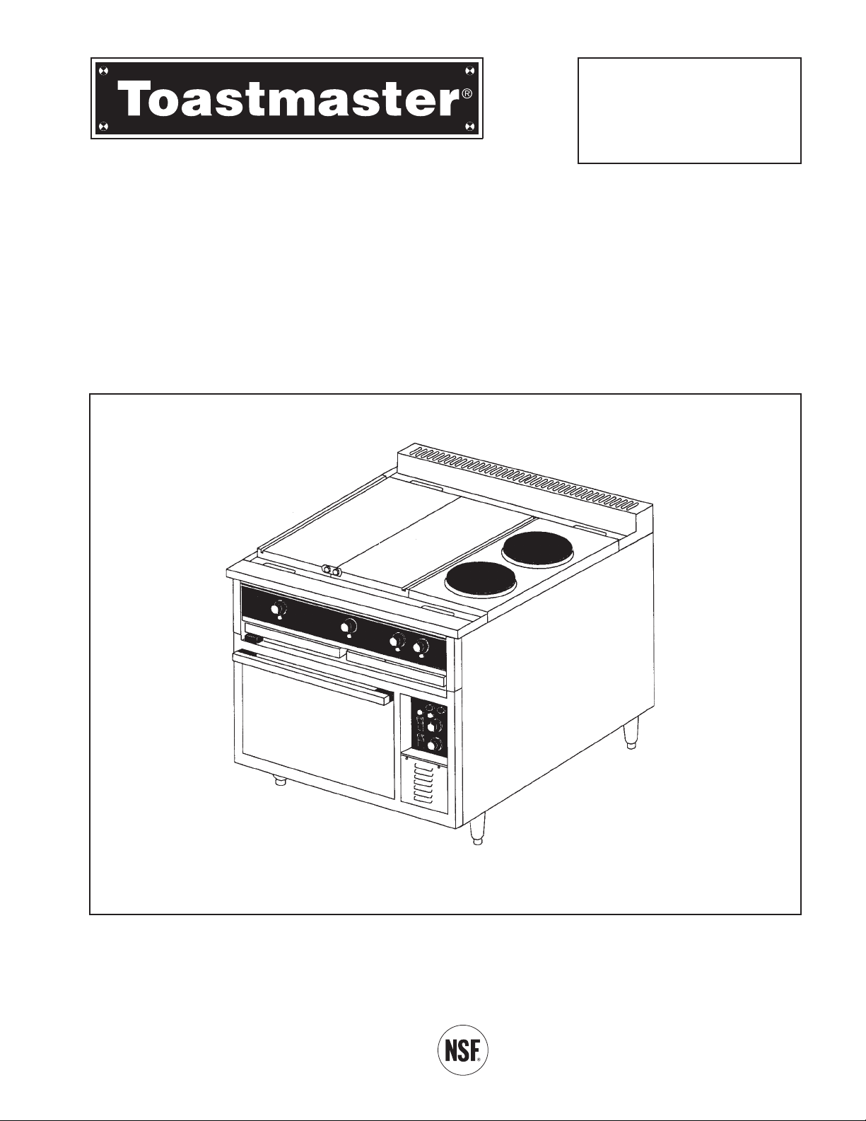
Oven Range
Model RH36, MH36
Manual 1189333 Rev 0 (03/07)
$30..00 Oven Range
IMPORTANT FOR FUTURE REFERENCE
Please complete this information and retain
this manual for the life of the equipment:
Model #: _________________________
Serial #: _________________________
Date Purchased: _________________
Manual 2M-1189333 Rev P (12/09)
$30.00
Page 2

WARNING
FOR YOUR SAFETY, DO NOT STORE OR USE GASOLINE OR
OTHER FLAMMABLE VAPORS AND LIQUIDS IN THE VICINITY
OF THIS OR ANY OTHER APPLIANCE.
WARNING
In case of fire, de-energize the Oven Range at its main discon-
nect switch/circuit breaker. Switching OFF the power to the Oven
Range allows it to cool, making it easier to extinguish a fire.
WARNING
ONLY use a CO
2
or other fire extinguisher suitable for grease, oil,
and electrical equipment fires. Do NOT try to stop a grease fire by
pointing the fire extinguisher nozzle directly on the burning
grease. Direct the nozzle to the outside of the flames to prevent
them from spreading. Gradually, spray closer to the center of the
flames, to cool and smoother them.
CAUTION
DO NOT move the Oven Range while cooking.
Pots of liquid could spill, causing injury.
NOTICE
Contact your local authorized Service Agency to perform
maintenance and repairs. A Service Agency directory is supplied
with your oven.
NOTICE
Using any parts other than genuine Toastmaster factory-supplied
parts relieves the manufacturer of all liability.
NOTICE
Toastmaster (Manufacturer) reserves the right to change
specifications and product design without notice. Such revisions do
not entitle the buyer to corresponding changes, improvements,
additions or replacements for previously purchased equipment.
I
RH36 & MH36 INSTALLATION & OPERATIONS MANUAL 2M-1189333
Page 3

PROBLEMS, QUESTIONS or CONCERNS
Before you proceed consult you authorized Toastmaster service agent directory
or
Call the Technical Service & Parts Department at 1-800-807-9054.
Table of Contents
SECTION 1
DESCRIPTION . . . . . . . . . . . . . . . . . . . . . . . . . . . . . . . . . . . 1
A. Oven Base . . . . . . . . . . . . . . . . . . . . . . . . . . . . . . . 1
B. Range . . . . . . . . . . . . . . . . . . . . . . . . . . . . . . . . . . . 2
C.Specications . . . . . . . . . . . . . . . . . . . . . . . . . . . . . 7
SECTION 2
INSTALLATION . . . . . . . . . . . . . . . . . . . . . . . . . . . . . . . . . . . 9
A. Inspection For Shipping Damage . . . . . . . . . . . . . 9
B. Installation of Oven Range . . . . . . . . . . . . . . . . . .10
C. Assembling of Oven Range. . . . . . . . . . . . . . . . . .11
D. Electrical Connection. . . . . . . . . . . . . . . . . . . . . . .11
E. Initially Cleaning the Griddle and/or Hot Plates . . .11
F. Testing the Installation . . . . . . . . . . . . . . . . . . . . . .12
G. Marine Oven Range Installation On Curb . . . . . . .12
H. Dimension Drawings . . . . . . . . . . . . . . . . . . . . . 13-14
SECTION 3
OPERATION . . . . . . . . . . . . . . . . . . . . . . . . . . . . . . . . . . . . .15
I. Component Function and Location . . . . . . . . . . . .15
II. Control Functions and Location. . . . . . . . . . . . . . .16
III. Operation. . . . . . . . . . . . . . . . . . . . . . . . . . . . . . . .19
IV. Time and Temperature Charts . . . . . . . . . . . . . . . .24
SECTION 4
PARTS LIST . . . . . . . . . . . . . . . . . . . . . . . . . . . . . . . . . . . . .29
Overall Drawing Parts List . . . . . . . . . . . . . . . . . . . . .30
Convection Oven . . . . . . . . . . . . . . . . . . . . . . . . . . . .34
Deck Oven . . . . . . . . . . . . . . . . . . . . . . . . . . . . . . . . .36
Vents and Marine Rails . . . . . . . . . . . . . . . . . . . . . . . .38
SECTION 5
SCHEMATICS . . . . . . . . . . . . . . . . . . . . . . . . . . . . . . . . . . . .40
Electrical Schematics & Wiring . . . . . . . . . . . . . . . . 41-83
RH36 & MH36 INSTALLATION & OPERATIONS MANUAL 2M-1189333
II
Page 4

This page intentionally left blank
III
RH36 & MH36 INSTALLATION & OPERATIONS MANUAL 2M-1189333
III
Page 5
SECTION 1
DESCRIPTION
I. Description
Toastmaster Model RH36 and MH36 electric oven ranges are rated heavy duty for commercial use. The oven
range consists of a range top fastened to an oven base. There is a marine kit available which qualify it for
shipboard use. The marine features are an oven door latch, grease tray latch, bolt-down legs , range top
adjustable sea rails and a grab bar across the front.
A. OVEN BASE
the oven base can be either a deck oven or convection oven.
1. Deck Oven (“D” in Model #, example RH36D1)
The deck oven base has an aluminized steel inner lining, removable deck of rigidized steel, vent with
damper and fully gasketed landing shelf type stainless steel lined door. The oven is insulated on all
sides and is equipped with one slide-in rack. Heating is accomplished with top and bottom formed
tubular heating elements which are each controlled by a 3-heat (low, medium, high) switch. The deck
oven has a thermostatic control with a temperature range of 200oF to 550oF (93oC to 287oC). The
oven will preheat to 450oF (232oC) in 20 minutes.
2. Convection Oven (“A” in Model #, example RH36C1)
The convection oven has removable stainless steel oven liners, vent damper and fully gasketed
landing shelf type stainless steel lined door. The oven is insulated on all sides. Removable rack
supports can accommodate six racks. The heating element is enclosed in the side of the oven cavity
and encircles the oven blower fan. The convection oven has a thermostatic control with a
temperature range of 150oF to 450oF (65oC to 232oC). The oven will preheat to 450oF (232oC) in 15
minutes.
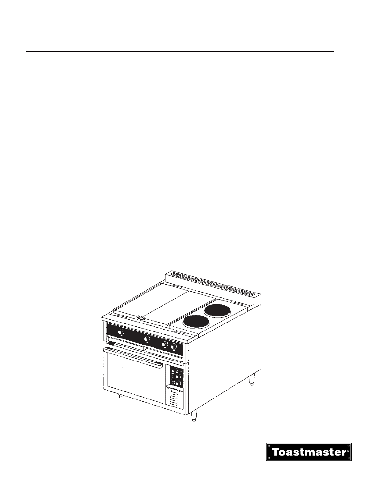
Figure 1-1
1
RH36 & MH36 INSTALLATION & OPERATIONS MANUAL 2M-1189333
Page 6
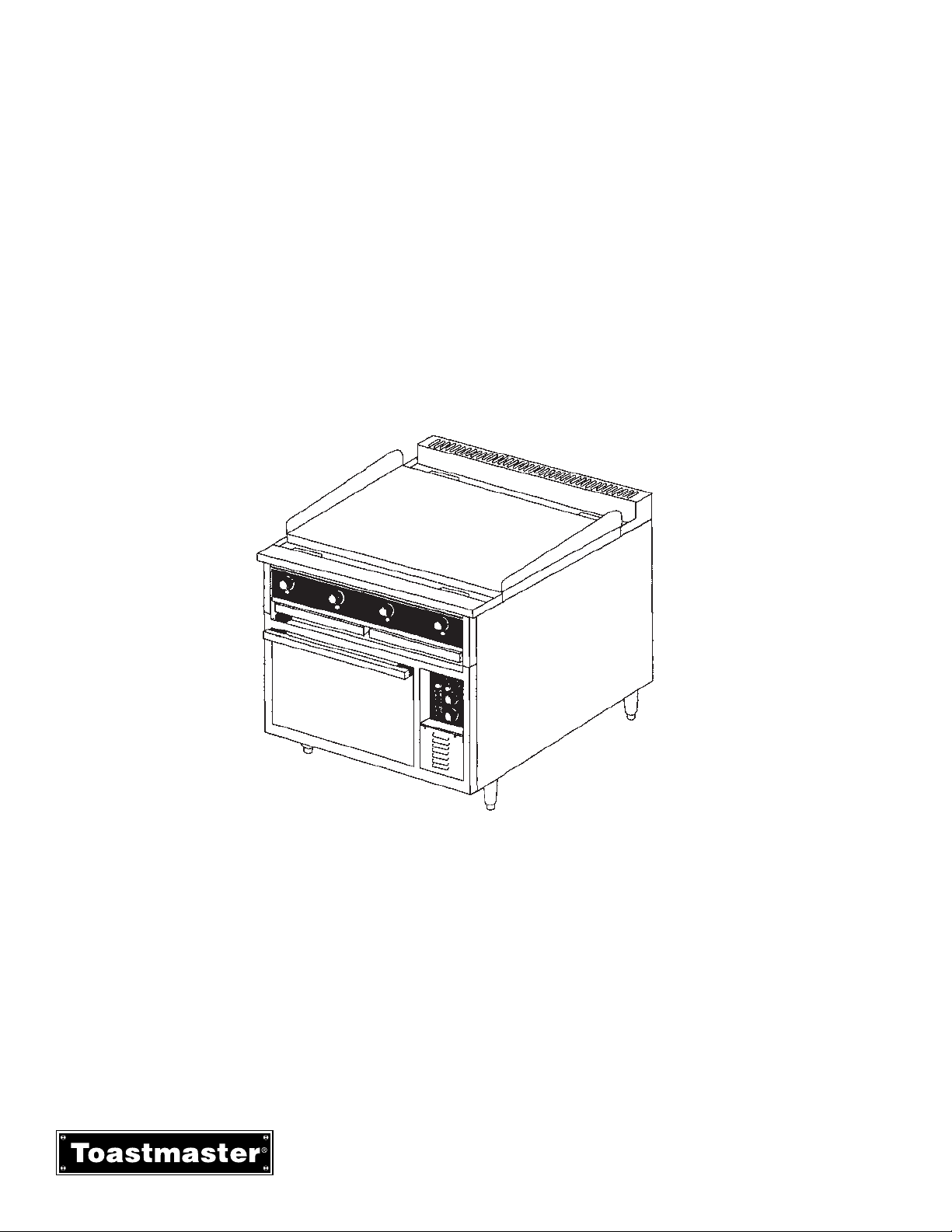
Figure 1-2
Griddle
Section 1 - Description
B. RANGE
The range can consist of up to 3 different components and the components can be configured in six
ways. Troughs with drip chutes are located at the front and rear for draining into two wide drawer type
receptacles
1. Range Components Descriptions
a. Griddle for griddling. The griddle can be either 24”x24” or 24” x 36”. The griddles are controlled by
thermostats. The 24”x24” griddle has a thermostat control for each of two 12”x24” zones and the 24”x
36” griddle has a thermostat for each of four 9”x24” zones. The griddle zones have a temperature
range of 150oF to 450
o
F (65
o
C to 232oC) and will preheat to 400oF (204oC) in 12 minutes.
RH36 & MH36 INSTALLATION & OPERATIONS MANUAL 2M-1189333
2
Page 7
b. 12”x24” Hot Plate for stock pot cooking (Not recommended for griddling). The hot plates are thermostatically controlled and have a temperature range of 250oF to 850oF (121oC to 454oC) and will preheat to
400oF (204oC) in 12 minutes
Section 1 - Description
c. Round Hot Plate for stock pot cooking. The twin hot plates have a 9” diameter and are controlled by 3-
heat (low, medium, high) switches.
Figure 1-3
Hot Plate
Figure 1-4
Round Hot Plate
3
RH36 & MH36 INSTALLATION & OPERATIONS MANUAL 2M-1189333
Page 8
Section 1 - Description
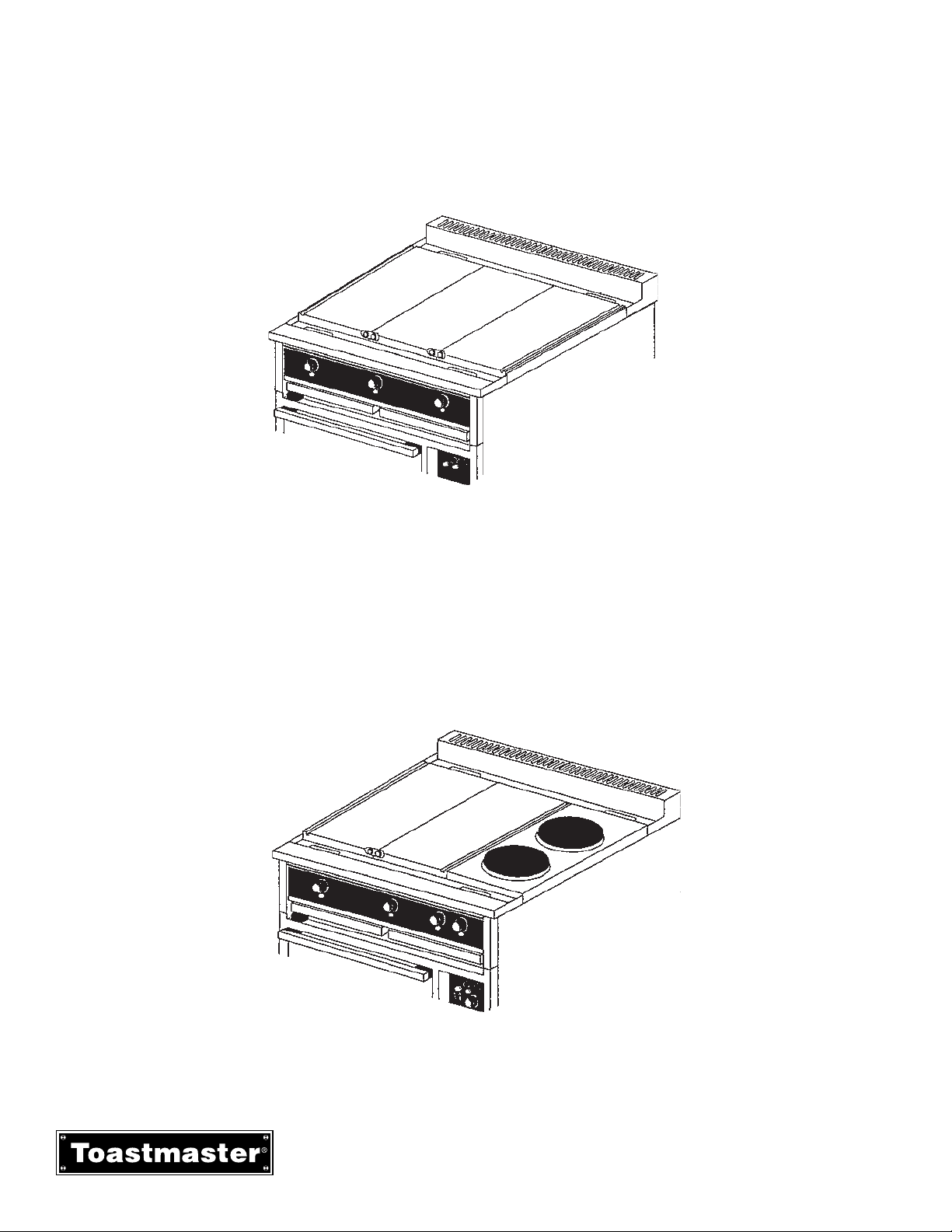
2. Range Top Configurations
a. All purpose TOP RH36C1, RH36D1. The all purpose top consists of three 12”x 24” hot plates. The
all purpose top is not recommended for griddling
b. Multi-Purpose Top RH36C2, RH36D2 The multi purpose top consists of two 12”x 24” hot plates
and two 9” round hot plates. The multipurpose top is not recommended for gridling.
Figure 1-5
All Purpose Plate
Figure 1-6
Multi-Purpose Top
RH36 & MH36 INSTALLATION & OPERATIONS MANUAL 2M-1189333
4
Page 9
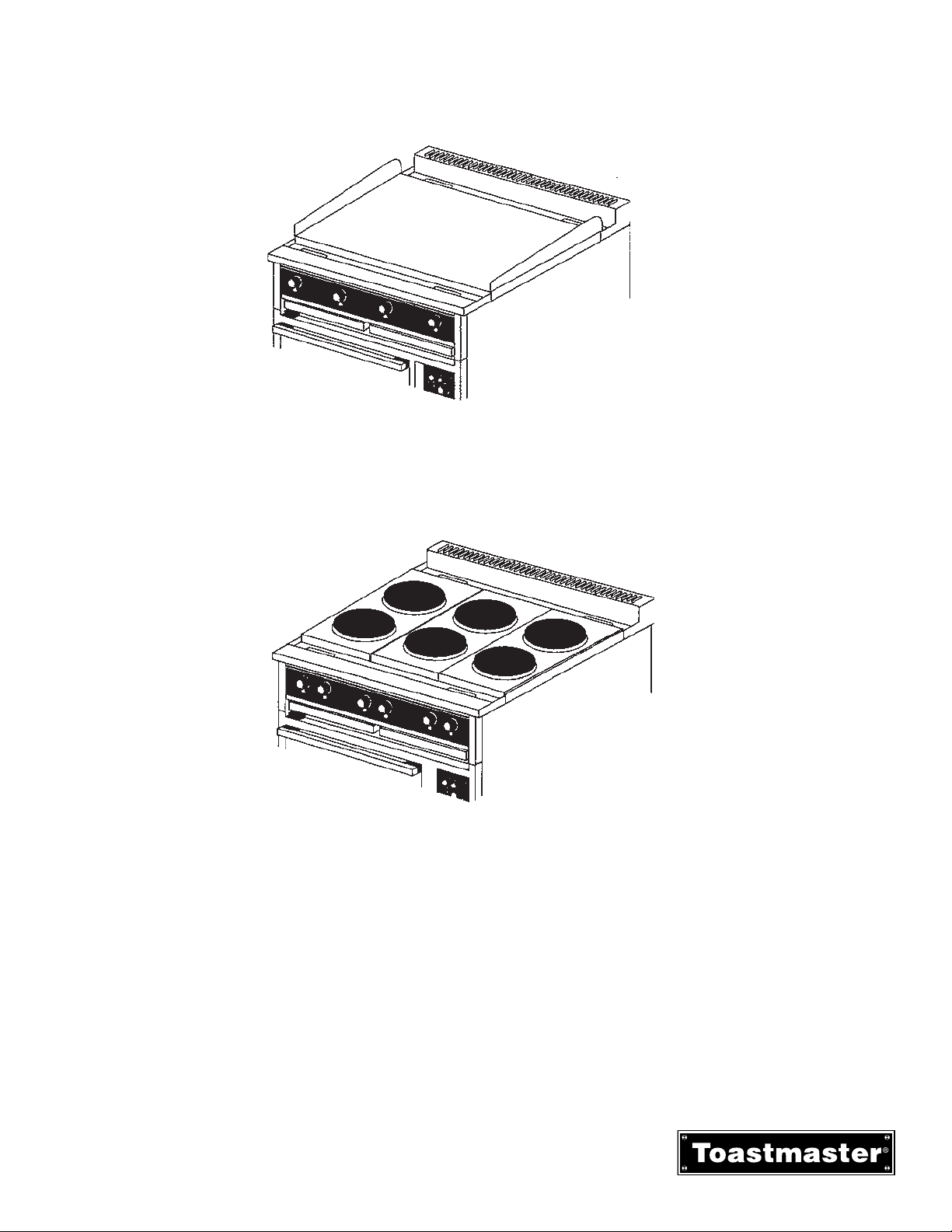
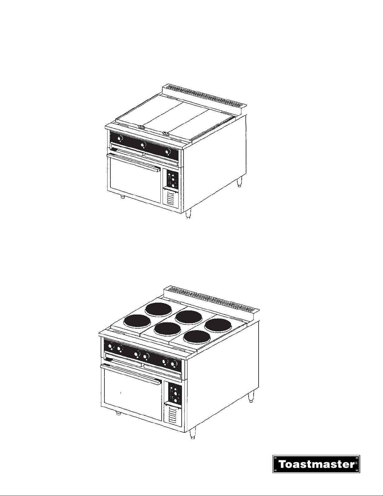
c. Griddling Top RH36C3, RH36D3. the griddle top consists of one 36”x24” griddle plate.
d. Round Hot Plate Top RH36C4, RH36D4. The round hot plate top consists of six 9” hot plates.
Figure 1-7
Griddle Top
Figure 1-8
Round Hot Plate
5
RH36 & MH36 INSTALLATION & OPERATIONS MANUAL 2M-1189333
Page 10
Section 1 - Description
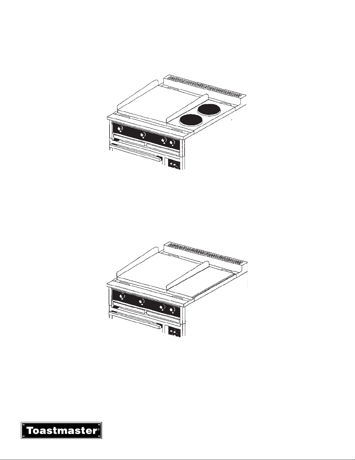
e. Griddle/Round Hot Plate Top RH36C6, RH36D6. The griddle/round hot plate top consists of one
24”x24” griddle and two 9” round hot plates.
f. Griddle 12”x24” Hot Plate Top RH36C7, RH36D7. The griddle 12” x 24” hot plate top consists of
one 24” x24” griddle and one 12”x24” hot plate.
Figure 1-9
Griddle/Round Hot Plate
Figure 1-10
Griddle/Hot Plate
RH36 & MH36 INSTALLATION & OPERATIONS MANUAL 2M-1189333
6
Page 11

NOTICE
Toastmaster (Manufacturer) reserves
the right to change specifications and
product design without notice. Such
revisions do not entitle the buyer to
corresponding changes, improvements,
additions or replacements for previously
purchased equipment.
Section 1 - Description
C. Specifications
OVEN RANGE MODELS SE36
Overall Dimensions
Width 36” (91.5cm)
Depth 38-3/4” (96.4cm)
Height 38-1/4” (97cm)
Net Weight
Model RH36C1 & MH36C1 569 lb (258 kg)
Model RH36C2 & MH36C2 515
lb (234 kg)
Model RH36C3 & MH36C3 588 lb(267 kg)
Model RH36C4 & MH36C4 455 lb (207 kg)
Model RH36C6 & MH36C6 515 lb (234 kg)
Model RH36C7 & MH36C7 545 lb (247 kg)
Model RH36D1 & MH36D1 569 lb (258 kg)
Model RH36D2 & MH36D2 515 lb (234 kg)
Model RH36D3 & MH36D3 588 lb (267 kg)
Model RH36D4 & MH36D4 497 lb (226 kg)
Model RH36D6 & MH36D6 515 lb (234 kg)
Model RH36D7 & MH36D7 545 lb (247 kg)
Shipping Weight
Model RH36C1 & MH36C1 610 lb (227 kg)
Model RH36C2 & MH36C2 570 lb (259 kg)
Model RH36C3 & MH36C3 610 lb(277 kg)
Model RH36C4 & MH36C4 485 lb (220 kg)
Model RH36C6 & MH36C6 570 lb (259 kg)
Model RH36C7 & MH36C7 545 lb (247 kg)
Model RH36D1 & MH36D1 569 lb (258 kg)
Model RH36D2 & MH36D2 515 lb (234 kg)
Model RH36D3 & MH36D3 588 lb (267 kg)
Model RH36D4 & MH36D4 497 lb (226 kg)
Model RH36D6 & MH36D6 515 lb (234 kg)
Model RH36D7 & MH36D7 545 lb (247 kg)
Construction -
---------- Welded Angle Iron ----------
Finish: ---------- Stainless Steel Front Sides and Top ----------
---------- Aluminized Steel Back ----------
Electrical Specifications Refer to Section 5
7
RH36 & MH36 INSTALLATION & OPERATIONS MANUAL 2M-1189333
Page 12

NOTES
Section 1 - Description
RH36 & MH36 INSTALLATION & OPERATIONS MANUAL 2M-1189333
8
Page 13

SECTION 1
INSTALLATION
A. Inspect for Shipping Damage
All shipping containers should be examined for damage before and during unloading. This equipment was
carefully inspected and packaged at the factory. the freight carrier has assumed responsibility for its safe
transit and delivery. If equipment is received in damaged condition, either apparent or concealed, a claim
must be made with the delivering carrier.
1. Apparent Damage or Loss - If damage or loss is apparent it must be noted on the freight bill or express
receipt at the time of delivery, and must be signed by the carrier’s agent (driver). If this is not done , the
carrier may refuse the claim. The carrier will supply the necessary claim forms.
2. Concealed Damage or Loss - If damage or loss is NOT apparent until after equipment is unpacked, a
request for inspection of concealed damage must be made with the carrier within 15 days. The carrier will
make an inspection and will supply necessary claim forms. Be certain to retain all contents plus external and
internal packaging materials for inspection.
SECTION 2
9
RH36 & MH36 INSTALLATION & OPERATIONS MANUAL 2M-1189333
Page 14
Section 2 - INSTALLATION
B. Inspect of Oven Range
The oven range can be shipped assembled or the range top module and the oven can be packed in separate
cartons. If the oven range is shipped assembled simply remove the metal banding straps and packing materials and move it to the permanent location.
If the oven range is packed in two separate cartons and must be moved through a narrow passage follow the
Pre-Installation instructions located on the outside of the carton. If the oven range does not have to be moved
through a narrow doorway then simply remove the metal banding straps and packing materials and move
each carton to the permanent location. Use the following procedure to assemble the range top and oven
modules.
Figure 2-1
RH36 & MH36 INSTALLATION & OPERATIONS MANUAL 2M-1189333
10
Page 15

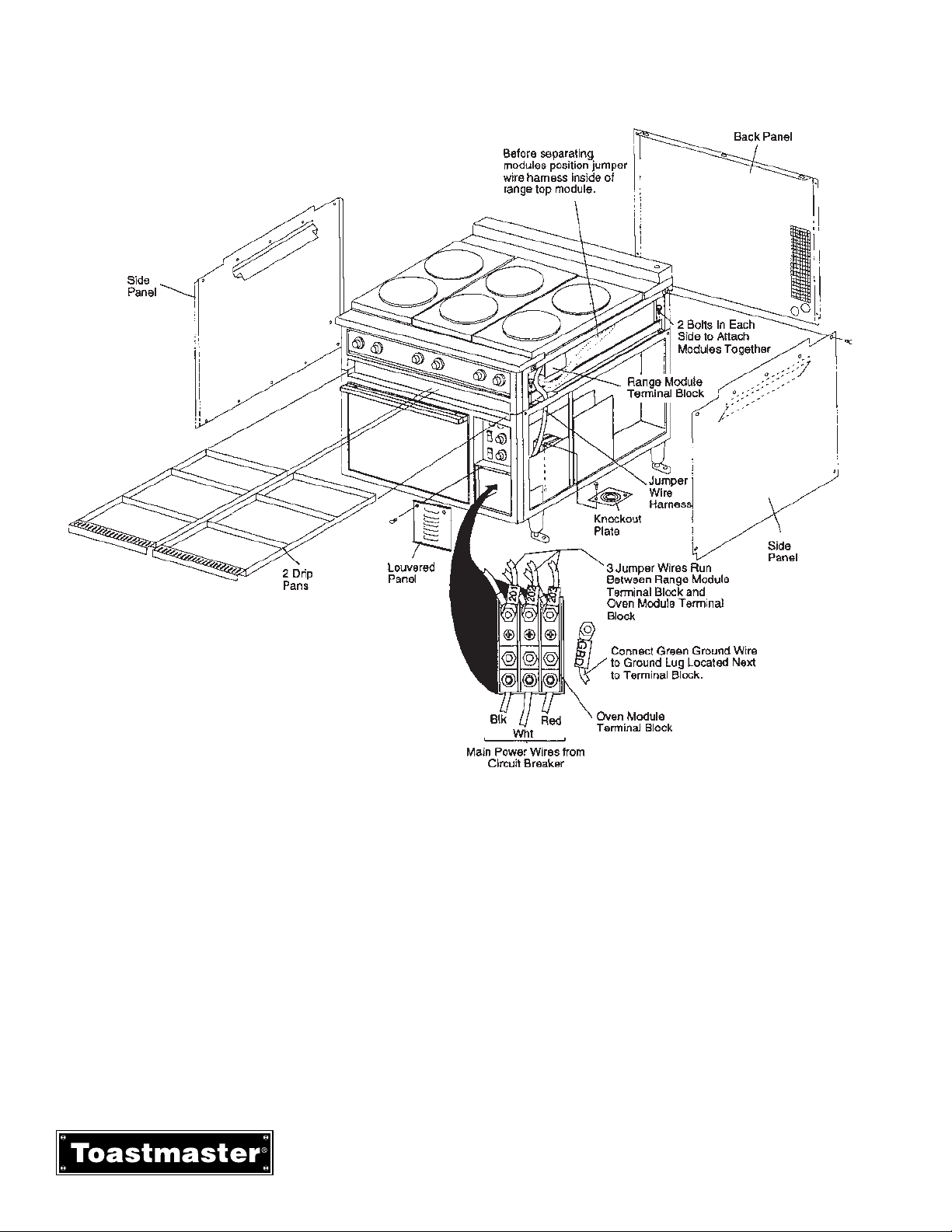
C. Assembling (Stacking) the Oven Module and Range Module
1. Move the range top module and the oven module to the area of their permanent location as directed in the
previous Paragraph “B” or the Pre-installation Instructions on the outside of the shipping carton.
2. Remove the following (refer to Figure 2-1):
• Two drip pans
• Two side panels
• Back cover
• Front louvered panel located below control panel
3. Place range top module in position on oven module.
4. Attach range top to oven using two 5/16” hex bolts on each side of the oven (4 bolts total, furnished).
Refer to Figure 2-1
5. Thread jumper wire harness from range top through oven base frame opening and connect wires marked
201, 202 and 203 to terminal block as shown in Figure 2-1.
6. Remove all remaining packing materials.
7. On Marine Oven Ranges bolt the oven range to the floor/deck using the leg brackets.
D. Electrical Connection
1. Remove the right side panel and the front louvered panel located below the control panel if they have not
already been removed.
2. Remove knockout plate located below terminal block on oven floor as shown in Figure 2-1. Knockout
desired hole in knockout plate. Reassembled knockout plate to floor of oven.
3. Connect main power wires from circuit breaker to terminal block as shown in Figure 2-1.
4. Reinstall all panels and drip pans that were removed.
E. Initially Clean the Griddle and/or 12” x 24” Hot Plate(s)
1. Remove the rust preventative material from the surface with a nonflammable grease solvent.
2. Wash the surface with warm water and a mild detergent.
3. Rinse with a damp cloth and wipe dry.
4. Griddle must then be seasoned immediately. Refer to Section 3, Operation, for procedure to follow.
Section 2 - INSTALLATION
11
RH36 & MH36 INSTALLATION & OPERATIONS MANUAL 2M-1189333
Page 16
F. Testing the Installation
1. Turn all range and oven controls to the OFF position.
2. Turn main power disconnect switch to ON
3. Check range top components by turning on one control at a time starting at the left side of the control
panel. Check that the component is starting to heat and then turn it off.
4. Check the oven controls.
a. Deck oven - Set thermostat control at 300°F (149°C). turn both the upper and lower heating element
switches to LOW. Check that both the upper and lower elements are starting to heat and then turn them
to OFF.
b. Convection oven - Set thermostat control to 300°F(149°C). Push fan switch LOW position. Turn oven
power switch ON. After a few minutes open oven door and check for heat. If oven is heating turn all
controls to OFF
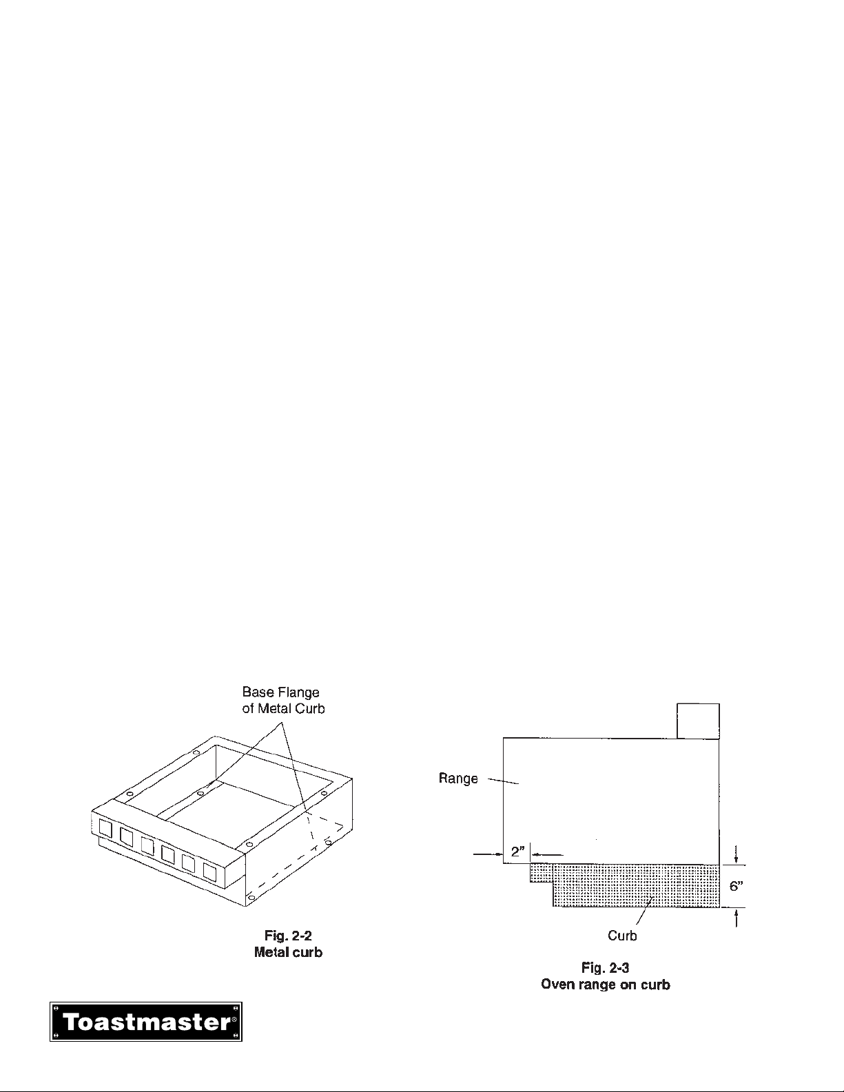
G. Marine Oven Range Installation on Curb
1. Installation of Oven Range on metal curb (shipped separately)
a. Bolt or weld base flange of metal curb (P/N33669) to floor of ship. See figure 2-2.
b. Position oven range on curb as shown in figure 2-3.
c. Remove oven side covers and use existing mounting holes to bolt oven range to top flange of curb.
2. Installation of Oven Range on existing curb.
a. Existing curb must be ventilated as shown on metal curb in Figure 2-3. The opening for circulation
must equal 8 square ft. (0.74 square meters).
b. Remove oven side covers and use existing mounting holes to bolt oven range to top of curb.
Section 2 - INSTALLATION
RH36 & MH36 INSTALLATION & OPERATIONS MANUAL 2M-1189333
12
Page 17
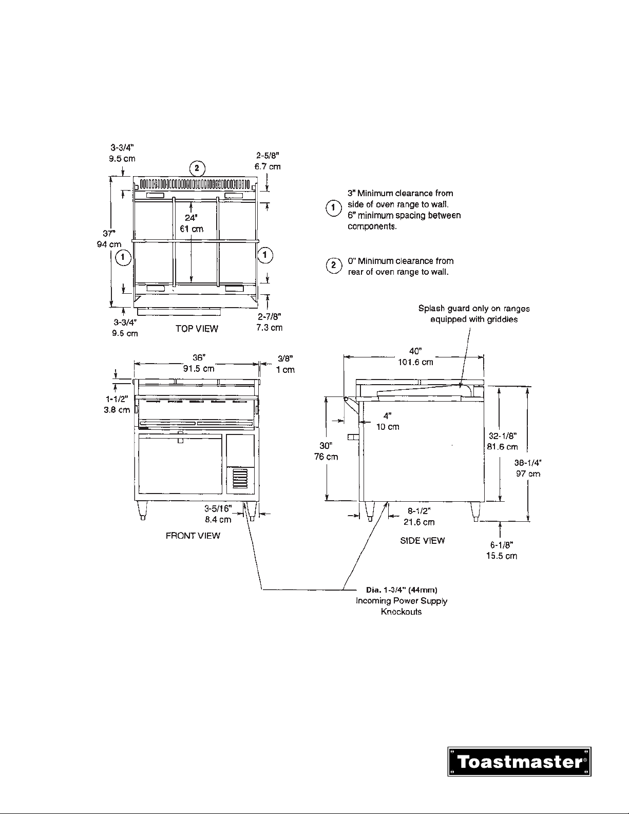
Figure 2-4
Section 2 - INSTALLATION
H. Dimension Drawings
13
RH36 & MH36 INSTALLATION & OPERATIONS MANUAL 2M-1189333
Page 18
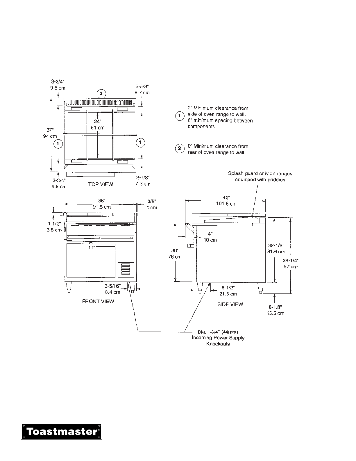
Section 2 - INSTALLATION
Figure 2-5
RH36 & MH36 INSTALLATION & OPERATIONS MANUAL 2M-1189333
14
Page 19
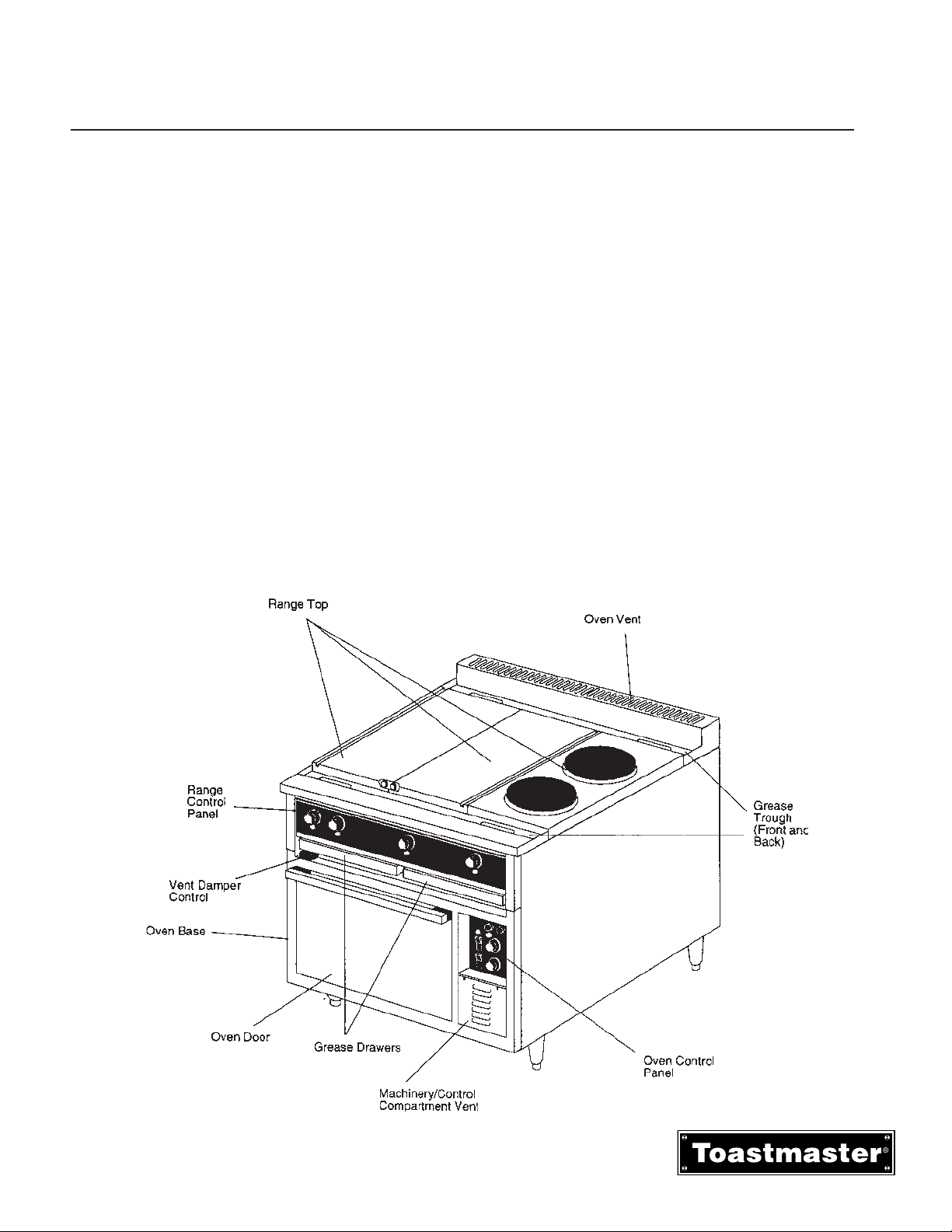
I. COMPONENT FUNCTION AND LOCATION
A. OVEN BASE Module - either a convection oven or deck oven base.
Convection Oven heating element located on side of oven cavity with the blower fan.
Deck Oven has a heating element at both the top and bottom of the oven cavity.
B. OVEN CONTROL PANEL - All Oven operating controls and indicators.
C. RANGE TOP - Configured six different ways which consist of griddle, round hot plate, and/or 12” x
24” hot plate.
D. RANGE TOP CONTROL PANEL - Contains all operator controls for range top operation
E. GREASE TROUGHS - In front and behind the Range Top cooking surfaces. (Grease chutes
provide drainage into the grease drawers)
F. GREASE DRAWERS - Containers for grease draining through the grease chutes from grease
troughs.
G. VENT DAMPER CONTROL - Controls the amount of moisture that can be vented from the oven.
Figure 3-1
Convection
SECTION 2
OPERATION
SECTION 3
15
RH36 & MH36 INSTALLATION & OPERATIONS MANUAL 2M-1189333
Page 20
Section 3 - OPERATION
II. Control Functions and Locations
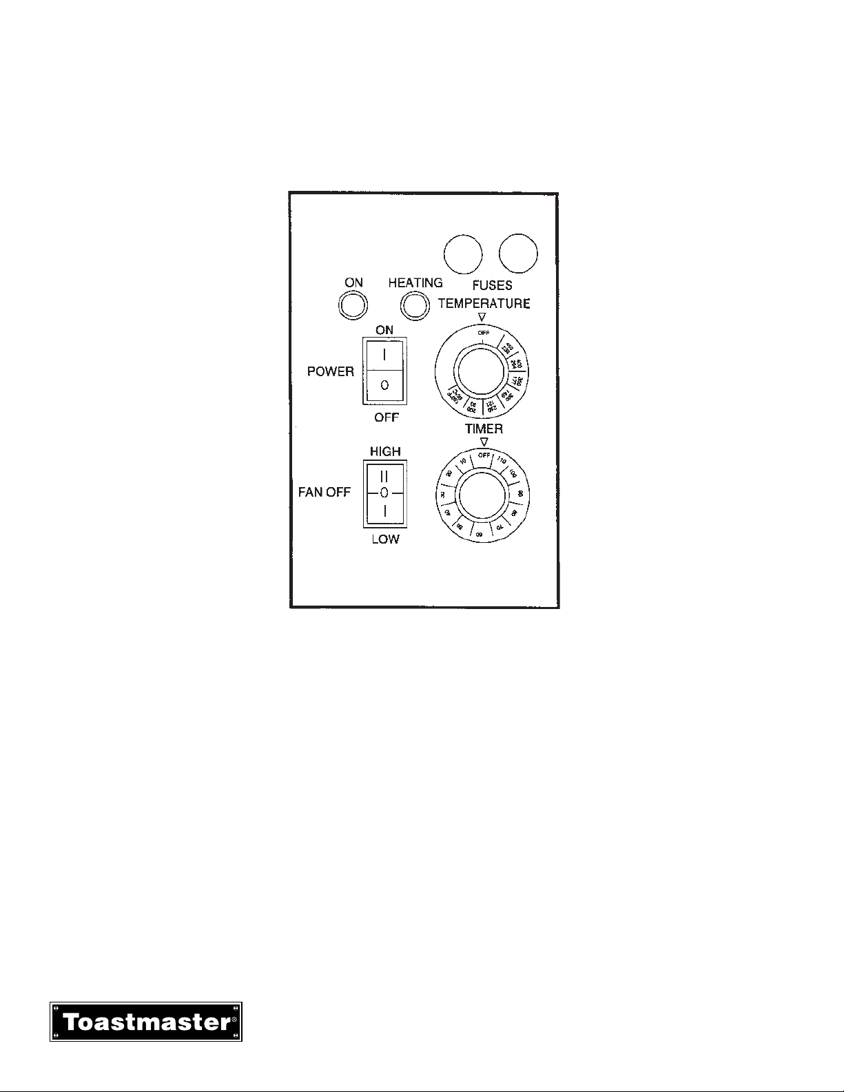
A. Convection Oven Control Panel
Figure 3-2
Convection Control Panel
1. Temperature Thermostat Control - adjustable from 150°F to 450°F(65°C to 232°C). The thermostat is
also provided with ON/OFF position. The oven will preheat to 450°F(232°C) in 15 minutes.
2. Heating Light - Amber light signals when oven is coming up to set temperature and heating element is
energized.
3. Power Switch - turns ON or OFF.
4. On Light - Green light signals when power is on.
5. Timer - Adjustable from 6 to 120 minutes.
6. Fan Switch - turns fan to LOW or HIGH speed and turns fan OFF. If fan switch is turned OFF the
heating element will not heat. Fan switch must be positioned in LOW or HIGH for oven to function.
7. Fuse Holders - Contains fuses.
RH36 & MH36 INSTALLATION & OPERATIONS MANUAL 2M-1189333
16
Page 21
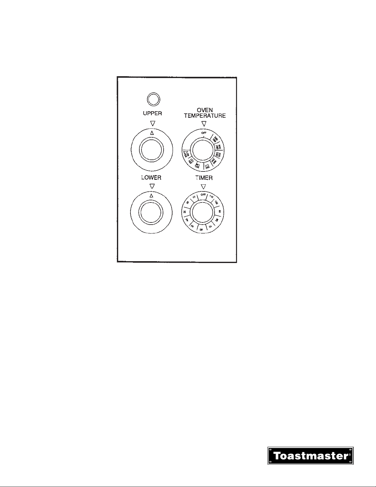
1. Temperature Thermostat Control - adjustable from 200°F to 500°F(93°C to 287°C). The thermostat is
also provided with ON/OFF position. The oven will preheat to 450°F(232°C) in 20 minutes.
2. Upper and Lower Heating Element Switches - are 3 position switches which adjust the heating
elements at low, medium or high. The heating element switches also have an OFF position.
3. Heating Light - Amber light signals when oven is coming up to set temperature and heating
element(s) is energized.
4. Timer - Adjustable from 6 to 120 minutes.
Figure 3-3
Deck Control Panel
Section 3 - OPERATION
B. Deck Oven Control Panel
17
RH36 & MH36 INSTALLATION & OPERATIONS MANUAL 2M-1189333
Page 22
Section 3 - OPERATION
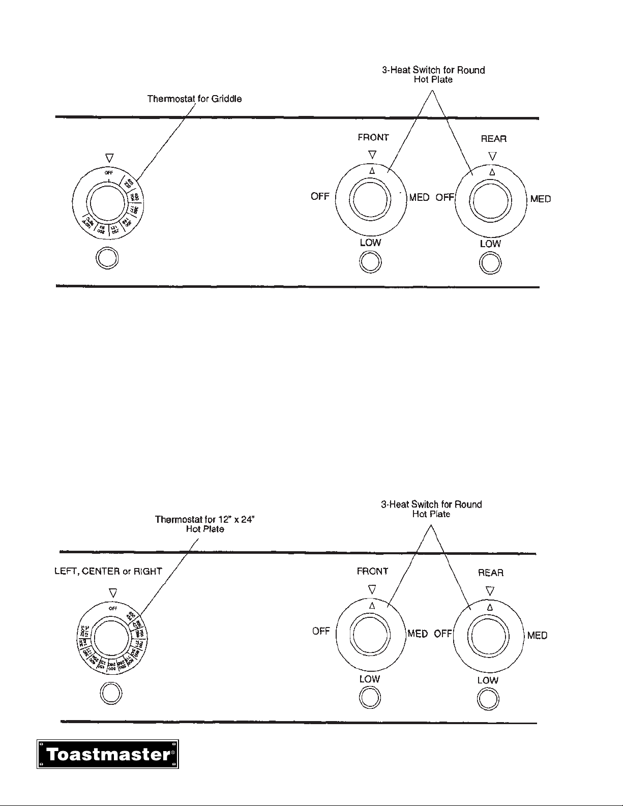
C. Range Top Controls
Figure 3-4
Range Top with Griddle Control
1. Griddle is controller by a Temperature Thermostat Control (see Figure 3-4) adjustable from 150°F to
450°F(65°C to 232°C). The griddle will preheat to 400°F(204°C) in 12 minutes. Adjacent green light
remains on while heating elements are energized and griddle is coming up to set temperature.
Griddles have independent heat zones each with its own heating element and temperature control. The
24” x 24” griddle has two 12” heat zones and the 24” x 36” griddle has four 9” heat zones.
2. 12” x 24” Hot Plate is controlled by a Temperature Thermostat Control (see Figure 3-5) adjustable from
250°F to 850°F (121°C to 455°C). The 12” x 24” hot plate will preheat to 400°F(204°C) in 12 minutes.
Adjacent green light remains on while heating elements are energized and griddle is coming up to set
temperature.
3. Round Hot Plate is controlled by a 3-heat switch. The switch positions are LOW, MEDIUM, HIGH and
OFF. Adjacent green light is always on while hot plate is on.
Figure 3-5
Range Top with Hot Plate Control
RH36 & MH36 INSTALLATION & OPERATIONS MANUAL 2M-1189333
18
Page 23

III. Operation
A. Convection Oven Operation
1. Set temperature control knob to the desired tenperature.
2. Push the oven power switch to the ON position.
3. Push the fan switch to the HIGH or LOW position. The LOW fan speed should be used for
delicate products or products with loose toppings such as pepperoni on a pizza. Use HIGH fan
speed for all other products that will not be affected by a fast air movement.
4. Allow oven to preheat to the set tmerpature. The amber signal light will remian on until the
temperature has been reached.
5. Place pans containing food products inot oven ans set timer for desired cook time. Refer to the
Time and Temperature Cahrts on the following pages for suggested cook times and temperatures. When placing pans in oven do not block air flow on sides or in back of oven cavity.
Blocking the air flow can cuase uneven cooking.
Opening the oven door too often will also cause uneven cooking. Keep oven door closed except
for necessary checking of food products.
6. Flue vent damper should be opened when cooking high moisture content foods. Pull the flue
vent handle to open the vent damper.
7. When timer signal that cooking time has elapsed remove food product and turn power switch,
temperture control and fna switch to OFF.
8. CONVECTION OVEN CLEANING
a. At the end of the day’s operation be sure the oven is turned off.
b. Open the oven door and allow it to cool down.
c. Remove the oven racks.
d. Remove the oveb rack hangers by lifting up and off the screw studs holding them in place.
e. Remove the baffle surrounding the fan by removeing the three screws on the front and pulling the
baffle forward.
f. All racks, rack hangers and fan baffle can be washed in warm soapy water, rinsed and wiped dry.
g. Wash the blower wheel.
h. Using a stiff brush (not sire), clean the interiot of baked on food particles. Using a mild detergent
and damp sponge wipe down the inside of the oven and door. Rinse and wipe dry. If these procedures are followed daily, it will prevent food particles from building up and creating hard to remove
stains. Do not use strong abrasives as they will scrathc the finish.
Section 3 - OPERATION
19
RH36 & MH36 INSTALLATION & OPERATIONS MANUAL 2M-1189333
Page 24

B. Deck Oven Operation
1. Set temperature control knob to the desired temperature.
2. Turn both Upper and Lower element switches to HIGH.
3. Allow oven to preheat to the set temperature. The amber signal light will remain on until the set temperature has been reached.
4. After oven is preheated set Upper and Lower element switches to desired setting (LOW, MEDIUM or
HIGH).
When roasting, the nest results are obtained by using balanced heat with both the Upper and Lower
element switches on HIGH. A measured top heat provides excellent coloring and a caramelized finish
to the meats, but where a seared or browned appearance is not desired, as in roasting fowl, the upper
oven element switch should be set on MEDIUM, LOW or OFF.
5. Place pans containing food products into oven. For baking and roasting, pans should be placed on the
intermediate rack. When roasting and baking pans are on both the deck and the rack the pans should
be rotated halfway through the cooking cycle.
When placing pans in oven do not block air flow on sides or in back of oven cavity. Blocking the air
flow can cause uneven cooking.
Opening the oven door too often will also cause uneven cooking. Keep oven door closed except for
necessary checking of food products.
6. Set timer for desired cook time. Refer to the Time and Temperature charts on the following pages for
suggested cook times and temperatures.
7. Flue vent damper should be opened when cooking high moisture content foods. Pull the flue vent
handle to open the vent damper.
8. When the timer signals that cooking time has elapsed remove food product and turn temperature
control and Upper and Lower element switches to OFF.
9. DECK OVEN CLEANING
a. At the end of the day’s operation be sure the oven is turned OFF.
b. Open the oven door and allow it to cool down.
c. Remove the oven rack and the oven deck at the bottom of the oven.
d. Oven rack and deck can be washed in warm soapy water, rinsed and wiped dry.
e Using a stiff brush (not wire), clean the interior of baked on food particles. Using a mild detergent
and damp sponge wipe down the inside of the oven and the oven door. Rinse and wipe dry. If these
procedures are followed daily, it will prevent food particles from building up and creating hard to
remove stains. Do not use strong abrasives as they will scratch the finish.
Section 3 - OPERATION
RH36 & MH36 INSTALLATION & OPERATIONS MANUAL 2M-1189333
20
Page 25

C. Griddle Operation
IMPORTANT: Do not turn griddle on before seasoning procedure has been completed.
IMPORTANT: If your griddle is new you must remove the rust preventative material before turning the
griddle on. Refer to Section 2, Installation, Paragraph E.
1. Griddle Seasoning Procedure.
a. Preheat the griddle to 300°F(149°C) and spread a light film of unsalted cooking oil or fat over the
surface with a soft cloth.
b. Allow griddle to stand this way for two minutes to give the oil an opportunity to work into the pores of
the metal and to form a smooth coating over the outside.
c. Wipe off excess oil and repeat Steps 1 and 2 at 350°F(175°C).
d. After the second step is complete wipe off excess cooking oil, set thermostat control knob for desired
temperature. The griddle is now ready for use.
2. Operating Hints and Safety
Although the finest materials, engineering and manufacturing facilities have provided for safety and
trouble -free operation, only proper use and maintenance will assure personnel safety and long life of the
equipment. The following are a few precautions and operating suggestions for use of the griddle.
a. Disconnect power to the griddle at the disconnect switch at the end of each day of operation.
b. Do not leave the griddle in operation without an attendant.
c. Turn thermostat dials down to 200°F(93°C) during idle periods. It takes only a few minutes to regain
operating temperatures.
d. Do not heat the entire griddle for cooking small amounts of food.
e. Various kinds of foods can be cooked at the same time by setting each section of the griddle at
different temperatures.
f. Use a spatula to push excess grease into troughs after each load of food is cooked. This will reduce
smoking of hot grease and carbonizing.
g. Do not leave griddle at high temperature when not in use or during idle periods. This will cause food
particles and grease film to carbonize.
3. Daily Griddle Operation and Maintenance.
Daily Pre-Operation
a. Season the griddle before operation daily, as described in Step 1 above.
b. Turn the temperature controls to the desired temperature and allow 15 minutes or preheat time
before loading griddle with food. Green signal light will remain on while heating elements are
energized and griddle is coming up to set temperature. This will allow time for the griddle surface to
be saturated with heat. Failure to allow sufficient preheat time will result in unsatisfactory cooking of
the first load. The following chart indicates cooking time and temperature for various type of food.
c. If a portion of the griddle is to be used for holding, then set the temperature controls for different
temperatures.
Section 3 - OPERATION
21
RH36 & MH36 INSTALLATION & OPERATIONS MANUAL 2M-1189333
Page 26

Section 3 - OPERATION
Daily Post Operations:
a. Cleaning the Griddle Surface
AA. Good cooking requires clean equipment. To provide evenly cooked and perfectly
browned foods, keep the griddle surface free fo carbonized grease. Carbonized grease
on the griddle surface hinders the transfer of heat from the griddle surface to the food.
This also results un spotty browning, decreased cooking efficiency, and worst of all,
carbonized brease tends to cling to the griddled foods, giving them a highly unsatisfactory and unappetizinf appearance.
BB. At the end of each day of operation or at the end of each shirt, thoroughly clean the front
and rear grease troughs and the chutes into grease drawers.
CC. Clean the griddle surface woth a pumice or griddle stone by rubbing with the grain of the
metal while the griddle surface is still warm. Wipe griddle clean of residue from the
griddle stone.
b. Clening - Wipe down sides of griddle and all areas around griddle to keep them free of splashed
grease.
AA. Clean all surrounding surfaces of the griddle with warm water and a mild detergent daily.
BB. Rinse and wipe off excess water.
CC. Polish with a dry soft cloth.
NOTE: This simple treatment not only keeps the equipment dirt free and sparkling, it also
eliminates the danger of grease accumulation forming hard to remove stains.
c. Cleaning the grease drawer - Empty each gresae drawer as often as necessary, but they must be
emptied at the end of ech day of operation or the end of each shift. Also wash out grease drawers
with hot water and a mild detergent. Wipe dry and replace in range. NOTE: Marine ranges are
equipped with a grease drawer latch which must be held depressed as the grease drawers are
removed.
RH36 & MH36 INSTALLATION & OPERATIONS MANUAL 2M-1189333
22
Page 27

Section 3 - OPERATION
D. 12” x 24” Hot Plate Operation
IMPORTANT: If your hot plate is new you must remove the rust preventative material before turning
the griddle on. Refer to Section 2, Instalaltion, Paragraph E.
1. Turn the termperature controls to the desired temperature and allow 15 minutes of preheat timer
before using the hot plate. the green signal light will remain on while the heating elements are
eneergized and the hit plate is coming up to set temperature.
2. When hot plate is preheated place pots or vessels onto hot plate for cooking.
3. HOT PLATE CLEANING.
a. Wash range with warm soapy water, rinse and wipe dry.
b. Be sure to clean all surfaces around and on the hot plates.
c. Polish with a soft cloth.
E. Round Hot Plate Operation
1. Turn the 3-heat switch to LOW, MEDIUM or HIGH. Allow the hot plate to preheat for 10 minutes
and then place pots or vessels onto hot plate for cooking.
2. Green signal light will remian on until 3-heat switch is turned to the OFF position.
3. ROUND HOT PLATE CLEANING
a. Wash range with warm soapy water, rinse and wipe dry.
b. Be sure to clean all surfaces around and on the hot plates.
c. Polish with a soft dry cloth.
F. Marine Ranges
Marine ranges are provided with a full width grab bar, 6” marine bolt down legs, and oven door latch and sea
rails to prevent movement of pots on range top.
The range top sea rails may have to be repositioned when various size pots or vessels are used.
23
RH36 & MH36 INSTALLATION & OPERATIONS MANUAL 2M-1189333
Page 28

Section 3 - OPERATION
IV. Time and Temperature Charts
DECK OVEN BAKING TIME AND TEMPERATURE
TOP BOTTOM TIME IN
PRODUCT TEMPERATURE SWITCH SWITCH MINUTES
Two Crust Pies 400F° - 425°F(204C° - 218°C) Medium High 40-60
Open Face Pies 400F° - 425°F(204C° - 218°C) Medium High 35-50
Pumpkin Pies 375°F - 400°F(190°C - 204°C) Medium Medium 35-50
Custard Pies 375°F - 400°F(190°C - 204°C) Medium Medium 35-50
Meringue Pie (Brown) 425°F - 450°F(218°C - 232°C) High Of
f 5-6
Pie Shells 400°F - 425°F(204°C - 218°C) Medium Medium 20-30
Parker House Rolls 400°F - 425°F(204°C - 218°C) Medium Medium 20-30
Whole Wheat Rolls 375°F - 400°F(190°C - 204°C) Medium Medium 20-30
Danish Rolls 375°F - 400°F(190°C - 204°C) Medium Medium 20-30
Sweet Rolls 375°F - 400°F(190°C - 204°C) Medium Medium 20-30
Kolacky 375°F - 400°F(190°C - 204°C) Medium Medium 10-15
Tea Biscuits 375°F - 400°F(190°C - 204°C) Medium Medium 20-25
Corn Bread 400°F - 425°F(204°C - 218°C) Medium Medium 25-35
Cup Cakes 400°F - 425°F(204°C - 218°C) Medium Medium 15-20
Layer Cakes 350°F - 375°F(176°C - 190°C) Medium Medium 20-30
Loaf Cakes 350°F - 375°F(176°C - 190°C) Off Medium 45-60
Angel Food Cakes 300°F - 325°F(149°C - 163°C) Medium Medium 40-50
Puddings 325°F - 375°F(163°C - 190°C) Medium Medium 35-60
Baked Apples 300°F - 325°F(149°C - 163°C) Low Low 60-70
* Used when the crust and filling are baled as a unit. When the crust is pre-baked most bakers use a temperature
of approximately 300°F - 350°F(149°C - 176°C).
NOTE: The data in this chart is of a general nature and is suggested for use as a guide only. Experience will, of
course, dictate variations that best fit your baking requirement.
RH36 & MH36 INSTALLATION & OPERATIONS MANUAL 2M-1189333
24
Page 29

Section 3 - OPERATION
DECK OVEN ROASTING TIME AND TEMPERATURE
CONTROL INTERNAL MEAT MINUTES
PRODUCT SETTING TEMPERATURE PER POUND
Beef
Standing Rib. 3 Rib. 6-8 Pounds 300°F(149°C) Rare 140°F(60°C) 20
Med. 160°F(71°C) 25
Well 170°F(77°C) 30
Standing Rib. 7 Rib. 20-25 pounds 300°F(149°C) Rare 125°F(52°C) 13
Med. 140°F(60°C) 15
Well 150°F(65°C) 17
Rolled Rib. 7 Rib. 16-18 pounds 250°F(121°C) Well 150°F(65°C) 25
Rump or Chuck. 8-23 pounds 300°F(149°C) 140°F - 170°F(60°C - 77°C) 20 - 30
Round Rump. shank off. 50 pounds 300°F(149°C) 140°F - 170°F(60°C - 77°C) 12 - 16
Lamb
Leg. 7-8 pounds 300°F(149°C) 180°F(82°C) 30 - 35
Leg. 15-20 pounds 300°F(149°C) 160°F(71°C) 20 - 30
Shoulder 3
00°F(149°C) 180°F(82°C) 40 - 45
Breast, Stuffed 300°F(149°C) 175°F - 180°F(79°C - 82°C) 30 - 35
Pork
Ham Leg, 15 pounds 350°F(176°C) 185°F(85°C) 30 - 35
Ham Leg, 25 pounds 350°F(176°C) 185°F(85°C) 30 - 35
Ham Boned, 15 pounds 350°F(176°C) 185°F(85°C) 30 - 35
Loin 350°F(176°C) 185°F(85°C)
Boston Butt 350°F(176°C) 185°F(85°C) 45 - 50
Ham. Cured. 20 pounds 300°F(149°C) 160°F(71°C) 15 - 18
Veal
Leg. 16 pounds 300°F(149°C) 170°F(77°C) 22
Leg. 25 pounds 300°F(149°C) 170°F(77°C) 18 - 20
Shoulder. 15 pounds 300°F(149°C) 170°F(77°C) 25
Shoulder. Rolled. 15 pounds 300°F(149°C) 170°F(77°C) 35 - 40
Loin. 10 pounds 300°F(149°C) 170°F(77°C) 25 - 30
Fowl
Chicken. Dressed. 4-6 pounds 250°F - 300°F(121°C - 149°C) 190°F(88°C) 35 - 40
Duck. Dressed. 5-8 pounds 300°F(149°C) 190°F(88°C) 25 - 30
Turkey. Dressed. 14-19 pounds 300°F(149°C) 190°F(88°C) 20 -25
Turkey. Dressed. 27-33 pounds 300°F(149°C) 190°F(88°C) 15 - 20
NOTE: The above data is of general nature. Many factors such as size of bone, thickness of meat, temperature at
time of roasting, individual taste as to degree of doneness, seasoning, etc., must be taken into consideration. Pan
selection and cooking times will also be governed by total weight, number of pieces in load. Preheating for
roasting is unnecessary.
25
RH36 & MH36 INSTALLATION & OPERATIONS MANUAL 2M-1189333
Page 30

Section 3 - OPERATION
CONVECTION OVEN BAKING
TIME & TEMPERATURE
This chart provides recommended temperature and time settings plus a number of racks per oven for specific
food products. The times and temperature may, however, vary considerably due to weight of load, type of
utensils and recipe.
NO. OF TEMP TIME
PRODUCT SIZE OF PAN RACKS YIELD SETTING SETTING
Frozen Berry Pies, 22 oz, 9” dia 3 18 350°F(176°C) 34min
Frozen Fruit Pies, 46 oz 9” dia 3
12 350°F(176°C) 45-50min
Frozen Apple Pies, 22 oz 9” dia 3 18 350°-375°F(176°-190°C) 25-30min
Sheet Cake 18” x 26” 3 3 335°F(168°C) 16-18min
Corn Bread 18” x 26” 3 3 335°F(168°C) 25min
Bread, 1lb Loaves 2
16 340°F(171°C) 30min
Sugar Cookies, 3” dia 18” x 26” 3 144 300°F(149°C) 1
5min
Brownies 12” x 20” x 2” 3 6 350°F(176°C) 15min
Beef Pot Pies, 5” dia 5” dia 3 60 400°F(204°C) 30-35min
Turkey or Chicken Pot Pies 5” dia 3 60 400°F(176°C) 30-35min
Stuffed Peppers 2 350°F(176°C) 15-20min
Toasted Cheese Sandwiches 12” x 20” 3 90 400°F(204°C) 8min
Hamburger Patties, 5 per lb. 18” x 26” 5 144 400°F(204°C) 8-10min
Chicken, Qtrs. (2-1/2lb avg) 18” x 26” 3 75 350°F(176°C) 30min
Chicken Breast - Thigh 18” x 26” 3 350°F(176°C) 40min
Individual Pizza (Frozen) 5” dia 3 60 450°F(232°C) 5min
Halibut Steaks (5oz Frozen) 18” x 26” 3 90 350°F(176°C) 20min
Rolled Roast Beef (20lb. Avg) 2 80 300°F(149°C) 4 hours
Meat Loaf 2 325°F(163°C) 40-45min
Idaho Potatoes (8oz Avg) 20 per rack 3 60 400°F(204°C) 50min
RH36 & MH36 INSTALLATION & OPERATIONS MANUAL 2M-1189333
26
Page 31

Section 3 - OPERATION
GRIDDLE TIME AND TEMPERATURE
NOTE: All cooking times are approximate
CONTROL TIME ADVANCE
PRODUCT SETTING IN MINUTES PREPARATIONS
Canadian Bacon 350°F(176°C) 3 - 4 Slice (not too far in advance as meat will
darken) - Split edges to prevent curling.
Hamburgers 350°F(176°C) 3 - 4 Prepare recipe - Form patties - Seperate
with waxed paper - Refrigerate.
Cheeseburgers 350°F(176°C) 3 -4 A hamburger patty plus melt a slice of
cheese on top just before serving.
Corned Beef Patties 375°F(190°) 3 - 4 Open both ends of can - Slide out
contents of can - Cut into 3/8” slices.
Sausage Patties 350°F(176°C) 3 - 4 Form patties - Seperate with waxed
paper - Refrigerate.
Sausage Links 350°F(176°C) 3 Refrigerate for best results.
Poatato Patties 375°F(190°) 3 - 4 Cook-Mash-Season-Form patties using
1/4 cup measure.
American Fries Potatoes 375°F(190°) 3 - 4 Cook - Slice - Season.
French Toast 400°F(204°C) 4 -5 Prepare egg batter.
Scarmabled Eggs 300°F(149°C) 3 - 4 Prepare recipe
Pancakes 375°F(190°) 2 Prepare recipe.
Frankfurters 375°F(190°) 2 - 5
Minute Steaks 400°F(204°C) 3 - 4
Club Steaks 400°F(204°C) 3 - 5
Ham Steaks 400°F(204°C) 10
Beef Tenderloin 400°F(204°C) 5 - 7
Boiled Ham 375°F(190°) 2
Bacon 350°F(176°C) 6
Hard Fried Eggs 300°F(149°C) 3
Sofr Fried Eggs 300°F(149°C) 2
Sunny-Side Up Eggs 300°F(149°C) 3
27
RH36 & MH36 INSTALLATION & OPERATIONS MANUAL 2M-1189333
Page 32

NOTES
Section 3 - OPERATION
RH36 & MH36 INSTALLATION & OPERATIONS MANUAL 2M-1189333
28
Page 33

SECTION 4
PARTS LIST
Order parts by calling your
authorized Toastmaster Parts
Distributor, who has a complete
inventory of parts for all Toastmaster
equipment.
29
RH36 & MH36 INSTALLATION & OPERATIONS MANUAL 2M-1189333
Page 34

Section 4 - PARTS LIST
RH36 & MH36 INSTALLATION & OPERATIONS MANUAL 2M-1189333
30
Page 35

Section 4 - PARTS LIST
RH36 & MH36
OVERALL PARTS LIST
Item
Qty Part No Description
No
N2-7600083 12x24 PLATE CMPLT - RIGHT DRAIN 208V
N2-7600084 12X24 PLATE CMPLT - RIGHT DRAIN 240V
N2-7600086 12X24 PLATE CMPLT - RIGHT DRAIN 480V
N2-7600087 12X24 PLATE CMPLT - LEFT DRAIN 208V
N2-7600088 12X24 PLATE CMPLT - LEFT DRAIN 240V
N2-7600090 12X24 PLATE CMPLT - LEFT DRAIN 480V
N2-7600074 12X24 PLATE CMPLT - CENTER 208V
1 1
2
3 3
4 3
5 6 N2-20A2G1 ELEMENT CLAMP PLATE
6 3 1O-8500079 INSULATION
7 3 N2-F706A107 BAFFLE
8 4 2C-20A2G7 LATCH SCREW
9 4 N2-20A2G6 LATCH PLATE
10 4 2A-20A1G7 LATCH PIN
11 4 N2-34284 CLIP, RETAINING 12X24 HOTPLATE
12 2 N2-20A1G8 KEY STRIP
13 6 N2-F706A1013 BULB CLAMP
14 27 2C-F716A8803 CAP SCREW 1/4-20 X 3/8
15 30 2C-F706A8809 WASHER 1-1/4”
16 12 2C-2001184 STUD 1/4-20 X 1-5/8
17 12 2A-F706A8811 SPACER
18 30 2C-F706A8805 WASHER 1/4”
19 24 2C-F706A8807 HEX NUT 1/4-20, BRASS
20 1/3
21 2/6
22 1/3 N2-7610114 TWIN PLATE PANEL
23 1/3 N2-1132B8901 RETAINER BAR MOUNTING BRACKET
24 2/6 N2-34285 RETAINING CLIP
25 1/3 N2-30999 BOTTOM. PLATE
N2-7600075 12X24 PLATE CMPLT - CENTER 240V
N2-7600077 12X24 PLATE CMPLT - RIGHT DRAIN 480V
N2-7601872
N2-7601873
N2-7601875
1 N2-20XA1G1 12X24 PLATE ONLY DRAIN BOTH SIDES
2 N2-20A2G8 12X24 PLATE ONLY RIGHT OR LEFT
1 N2-20A2G9 12X24 PLATE ONLY CENTER
2T-3004281 THERMOSTAT
2R-2100094 T-STAT KNOB 250°F (121°C) - 850°F (454°C)
2N-F706A8703 ELEMENT 208V
2N-F706A8731 ELEMENT 240V
2N-F706A8729 ELEMENT 480V
N2-34797 TWIN PLATE ASSEMBLY 208V, 2600W
N2-33850 TWIN PLATE ASSEMBLY 240V, 2600W
N2-34278 TWIN PLATE ASSEMBLY 480V
2N-1132B8701 SOLID RND HEATING UNIT 208V ECO-2600W
2N-1132B8703 SOLID RND HEATING UNIT 240V ECO-2600W
2N-34127 SOLID RND HEATING UNIT 480V ECO-2600W
12X24 PLATE CMPLT - DRAIN BOTH SIDES
208V (USED ON MODELS RH36O7 & RH36D7)
12X24 PLATE CMPLT - DRAIN BOTH SIDES
240V (USED ON MODELS RH36O7 & RH36D7)
12X24 PLATE CMPLT - DRAIN BOTH SIDES
480V (USED ON MODELS RH36O7 & RH36D7)
Item
Qty Part No Description
No
N2-20G1A32 36X24 GRIDDLE PLATE CMPLT 208V
26 1
27 1 N2-20G1A36 36X24 GRIDDLE PLATE ONLY
28 4
29 4
30 4 N2-20G1A37 ELEMENT CLAMP PLATE
31 4 N2-20G1A38 ELEMENT BAFFLE
32 24 2C-F706A8802 WASHER 11/32 X 1-1/4
33 48 2C-F706A8807 HEX NUT, BRASS 1/4-20
34 24 2A-F706A8811 SPACER
35 28 2C-F706A8805 WASHER 1/4”
36 4 N2-7002270 THERMOSTAT BULB CLAMP
37 4 1O-8500079 INSULATION
38 1
39 1 N2-7603536 24X24 GRIDDLE PLATE ONLY
40 2
41 4 N2-F706A1013 THERMOSTAT BULB CLAMP
42 2
43 4 N2-20A2G1 ELEMENT CLAMP PLATE
44 26 2C-B301A8817 HEX NUT 1/4-20
45 20 2C-F706A8809 WASHER 1-1/4” OD
46 8 2A-F706A8811 SPACER
47 16 2C-F706A8805 WASHER 1/4”
48 2 1O-8500079 INSULATION
49 2 N2-F706A1017 BAFFLE
50 1 N2-33617 WELDMENT, EXT. PANEL LEFT HAND
51 1 N2-33618 WELDMENT, EXT. PANEL RIGHT HAND
52 1 N2-32849 REAR PANEL
53
54 1 N2-33616 PLATE COVER
55 1 N2-7007442 KNOCKOUT PLATE
56 1 N2-MALG06F KIT, MARINE LEG 6” SS ADJ.
57 1 N2-7007992 ACCESS PANEL
58 2 N2-7601840 GREASE DRAWER, HANDLE & ASSEMBLY
59 1 N2-32691 LATCH, MARINE
60 2
61 2 2A-33621 DOOR BUSHING
62 4 N2-7610657 WELDMENT, SPOUT GREASE
N2-20G1A302 36X24 GRIDDLE PLATE CMPLT 240V
N2-20G1A306 36X24 GRIDDLE PLATE CMPLT 480V
2T-3004257 THERMOSTAT
2R-2100059 T-STAT KNOB 150°F (66°C) - 450°F (232°C)
2N-7D1E1 ELEMENT 208V
2N-7D1E29 ELEMENT 240V
2N-7D1E28 ELEMENT 480V
N2-7603538 24X24 GRIDDLE PLATE CMPLT 208V
N2-7603539 24X24 GRIDDLE PLATE CMPLT 240V
N2-7603541 24X24 GRIDDLE PLATE CMPLT 480V
2T-3004257 THERMOSTAT
2R-2100059 T-STAT KNOB 150°F (66°C) - 450°F (232°C)
2N-F706A8703 ELEMENT 208V
2N-F706A8731 ELEMENT 240V
2N-F706A8729 ELEMENT 480V
1 2E-30905 TERMINAL BLOCK, 3-POLE
N2-34743 LATCH, GREASE DRAWER
N2-34741 RECIEVER FOR LATCH
31
RH36 & MH36 INSTALLATION & OPERATIONS MANUAL 2M-1189333
Page 36

Section 4 - PARTS LIST
RH36 & MH36 CONTINUED
Item
Qty Part No Description
No
63 4 2I-2700090 GASKET, SPOUT GREASE
64 1 N2-33693 ASSEMBLY, DOOR
65 1 N2-32692 PLATE, LATCH
66 2 2A-34081 SPACER, STEPPED - MARINE LATCH
67 1 N2-32572 ASSEMBLY, HANDLE DOOR
68 2 2A-3103164 SPACER, DOOR & DRAWER HANDLE
69 4 2V-2000320 HANDLE SCREWS 10/32 X 3-12
70 2 2V-3000058 BLACK HANDLE PLUG
2M-31795 DECAL RH36C3, RH36D3 CONTROL PANEL
2M-31796 DECAL RH36C4, RH36D4 CONTROL PANEL
NI --
2M-31794
2M-31793
N2-30926 CONTROL PANEL RH36D4
N2-31623 CONTROL PANEL RH36C3
DECAL RH36C2&C6, RH36D2&D6 CONTROL
PANEL
DECAL RH36C1&C7, RH36D1&D7 CONTROL
PANEL
RH36 & MH36 INSTALLATION & OPERATIONS MANUAL 2M-1189333
32
Page 37

NOTES
Section 4 - PARTS LIST
33
RH36 & MH36 INSTALLATION & OPERATIONS MANUAL 2M-1189333
Page 38

Section4-PARTSLIST
33, 34, 35, 36
IL2012
RH36 & MH36 INSTALLATION & OPERATIONS MANUAL 2M-1189333
34
Page 39

Section 4 - PARTS LIST
RH36 & MH36
CONVECTION OVEN PARTS LIST
Item No Qty Part No Description
2N-3027A8701 ELEMENT 6000W-208V
1 1
2 4 N2-3027A3083 ELEMENT SUPPORT
3 1 N2-30919 MOTOR BLOWER & ASSEMBLY 240V-480V
3A 1 2U-3002761 BLOWER MOTOR ONLY 208V-240V
4 1 2R-3103902 BLOWER WHEEL
5 1 N2-7610513 ELEMENT COVER, BLOWER BAFFLE
6 3 N2-3102541 SHELF ASSEMBLY
7 2 2B-3102540 SIDE RACK
8 1 2E-30905 TERMINAL BLOCK, 3-POLE
9 1 2E-28082-0010 TRANSFORMER 480V ONLY
10 1 2E-34401 CONTACTOR 208V-240V COIL
11 1 2P-30368 DOOR SPRING
12 1 2C-43685 EYE BOLT
13 1 N2-30369 CABLE ASSEMBLY
14 1 2R-7007809 PULLEY
15 1 2A-30359 AXLE
16 2 2C-3102937 RETAINER RING
17 1 2E-3003770 MICRO SWITCH
18 1 N2-32762 MOTOR DUCT
19 1 2I-34404 MOTOR DUCT SEAL
20 1 2E-30519 HIGH LIMIT SENSOR
21 AR 2E-32941 SWITCH 3HT
22 AR 2R-33365 KNOB SWITCH
23 AR
24 1 2T-2662A8701 THERMOSTAT, C.O. OVEN 150F (66C)-450F (232C)
25 1 2R-A710E8771 THERMOSTAT KNOB, C.O. OVEN 150°F (66°C) - 450°F (232°C)
26 1 2P-3004536 TIMER
27 1 2R-2100088 OVEN TIMER KNOB
28 1 2E-33436 SWITCH, ROCKER, DP/ST
29 1 2E-33437 SWITCH, ROCKER DP/DT
30 2
31 2
32 1 2M-91783 DECAL CONTROL PANEL (not shown)
33 AR 34700 BOLT
34 AR 3024A3141 BUSHING
35 AR 18A1S-2 COTTER PIN
36 AR 21176-0001 LOCK NUT
2N-3027A8711 ELEMENT 6000W-240V
2N-3027A8709 ELEMENT 6000W-480V
2E-33413 SIGNAL LIGHT, GREEN 250V
2E-33414 SIGNAL LIGHT, AMBER 250V
2E-33415 SIGNAL LIGHT, WHITE 250V
2E-33417 SIGNAL LIGHT, GREEN 480V
2E-33418 SIGNAL LIGHT, AMBER 480V
2E-33419 SIGNAL LIGHT, WHITE 480V
2E-1455A0341 FUSE HOLDER ASSEMBLY 480V
2E-1455A0339 FUSE HOLDER ASSEMBLY 240V
2E-1455A8793 FUSE 240V-10A
2E-1455A8794 FUSE 480V-10A
SUPPORTED BY SOUTHBEND
35
RH36 & MH36 INSTALLATION & OPERATIONS MANUAL 2M-1189333
Page 40

Section 4 - PARTS LIST
RH36 & MH36 INSTALLATION & OPERATIONS MANUAL 2M-1189333
36
Page 41

Section 4 - PARTS LIST
RH36 & MH36
DECK OVEN PARTS LIST
Item No Qty Part No Description
2N-3001761 INNER ELEMENT 1500W-208V
1 2
2 2
3 1 N2-30692 OVEN DECK
4 1 N2-30372 OVEN SHELF
5 1 N2-3024A3217 GUARD THERMOSTAT BULB
6 1 2P-30368 SPRING, DOOR
7 1 2C-43685 EYEBOLT
8 1 N2-30369 CABLE ASSEMBLY
9 1 2E-30905 TERMINAL BLOCK, 3POLE
10 1 2ER-7007809 SHEAVE, 3/16 DIA. CABLE (PULLEY)
11 1 2A-30359 AXLE
12 2 2C-3102937 RETAINER RING
13 2/6 2E-32941 SWITCH 3HT
14 2/6 2R-33365 KNOB SWITCH
15 AR
16 1 2T-3004238 THERMOSTAT DECK OVEN
17 1 2R-A710E8739 THERMOSTAT KNOB DECK OVEN 200°F-550°F
18 1 2P-3004536 TIMER
19 1 2R-210088 KNOB, TIMER
20 2 2E-32941 SWITCH 3HT
21 2 2R-33365 KNOB SWITCH
22 1 2M-31784 DECAL CONTROL PANEL DECK OVEN
2N-3001762 INNER ELEMENT 1500W-240V
2N-3001764 INNER ELEMENT 1500W-480V
2N-3001765 OUTER ELEMENT 1500W-208V
2N-3001766 OUTER ELEMENT 1500W-240V
2N-3001768 OUTER ELEMENT 1500W-480V
2E-33413 SIGNAL LIGHT, GREEN 250V
2E-33414 SIGNAL LIGHT, AMBER 250V
2E-33417 SIGNAL LIGHT, GREEN 480V
2E-33418 SIGNAL LIGHT, AMBER 480V
37
RH36 & MH36 INSTALLATION & OPERATIONS MANUAL 2M-1189333
Page 42

Section 4 - PARTS LIST
RH36 & MH36 INSTALLATION & OPERATIONS MANUAL 2M-1189333
38
Page 43

Section 4 - PARTS LIST
RH36 & MH36
VENTS & MARINE RAILS PARTS LIST
Item No Qty Part No Description
1 2 N2-33194 RAIL, SEA FRONT TO BACK LOOSE
2 1 N2-33195 RAIL, SEA LEFT TO RIGHT LOOSE
3 2 N2-20A2C77 RAIL, SEA FIXED RIGHT LEFT
4 6 N2-20A2C76 ANLE, SEA RAIL SECURITY
5 2 N2-20A2C75 RAIL, SEA FIXED FRONT BACK
6 1 N2-20A2C82 RAIL, HAND
7 1 N2-7001408 BRACKET, RAIL LIT MARINE
8 1 N2-7001409 BRACKET, RAIL RT MARINE
9 2 N2-7004267 POST, SEEA RACKS
10 1 2V-7000071 ROD, VENT RA
11 1 2R-2100053 KNOB, VENT “T” PULL/OPEN
12 1 N2-7610705 WELDMENT, FLAP VENT
13 1 N2-30412 WELDMENT, FLUE - OVEN SECTION
14 1 N2-30415 WELDMENT, FLUE - TOP SECTION
15 1 N2-32792 WELDMENT, FLUE - TOP SECTION
16 1 2A-2002305 VENT KNOB PIN
17 1 2C-18A12 COTTER PIN
18 4 2C-2000552 SCREW 5/16-18 X 3/4
19 2 2C-4113A8801 SCREW FHM 1/4-20 X 1/2
20 16 2C-2281 SCREW 5/16-18 X 7/16
21 16 2C-4039A8803 LOCKWASHER 5/16
22 12 2C-1411D8815 HEX NUT 5/16-18
23 1 N2-34518 STAINLESS STEEL LINER KIT
39
RH36 & MH36 INSTALLATION & OPERATIONS MANUAL 2M-1189333
Page 44

SECTION 5
SCHEMATICS
RH36 & MH36 INSTALLATION & OPERATIONS MANUAL 2M-1189333
40
Page 45

Section 5 - SCHEMATICS
RH36D1 SCHEMATIC
208/240V
41
RH36 & MH36 INSTALLATION & OPERATIONS MANUAL 2M-1189333
Page 46

Section 5 - SCHEMATICS
RH36D1 WIRING DIAGRAM
208/240V
RH36 & MH36 INSTALLATION & OPERATIONS MANUAL 2M-1189333
42
Page 47

Section 5 - SCHEMATICS
RH36D2 SCHEMATIC
208/240V
43
RH36 & MH36 INSTALLATION & OPERATIONS MANUAL 2M-1189333
Page 48

Section 5 - SCHEMATICS
RH36D2 WIRING DIAGRAM
208/240V
RH36 & MH36 INSTALLATION & OPERATIONS MANUAL 2M-1189333
44
Page 49

Section 5 - SCHEMATICS
RH36D3 SCHEMATIC
208/240V
45
RH36 & MH36 INSTALLATION & OPERATIONS MANUAL 2M-1189333
Page 50

Section 5 - SCHEMATICS
RH36D3 WIRING DIAGRAM
208/240V
RH36 & MH36 INSTALLATION & OPERATIONS MANUAL 2M-1189333
46
Page 51

Section 5 - SCHEMATICS
RH36D4 SCHEMATIC
208/240V
47
RH36 & MH36 INSTALLATION & OPERATIONS MANUAL 2M-1189333
Page 52

Section 5 - SCHEMATICS
RH36D4 WIRING DIAGRAM
208/240V
RH36 & MH36 INSTALLATION & OPERATIONS MANUAL 2M-1189333
48
Page 53

Section 5 - SCHEMATICS
RH36D6 SCHEMATIC
208/240V
49
RH36 & MH36 INSTALLATION & OPERATIONS MANUAL 2M-1189333
Page 54

Section 5 - SCHEMATICS
RH36D6 WIRING DIAGRAM
208/240V
RH36 & MH36 INSTALLATION & OPERATIONS MANUAL 2M-1189333
50
Page 55

Section 5 - SCHEMATICS
RH36D7 SCHEMATIC
208/240V
51
RH36 & MH36 INSTALLATION & OPERATIONS MANUAL 2M-1189333
Page 56

Section 5 - SCHEMATICS
RH36D7 WIRING DIAGRAM
208/240V
RH36 & MH36 INSTALLATION & OPERATIONS MANUAL 2M-1189333
52
Page 57

Section 5 - SCHEMATICS
RH36C1 SCHEMATIC
208/240V
53
RH36 & MH36 INSTALLATION & OPERATIONS MANUAL 2M-1189333
Page 58

Section 5 - SCHEMATICS
RH36C1 WIRING DIAGRAM
208/240V
RH36 & MH36 INSTALLATION & OPERATIONS MANUAL 2M-1189333
54
Page 59

Section 5 - SCHEMATICS
RH3621 SCHEMATIC
480V
55
RH36 & MH36 INSTALLATION & OPERATIONS MANUAL 2M-1189333
Page 60

Section 5 - SCHEMATICS
RH36C2 WIRING DIAGRAM
480V
RH36 & MH36 INSTALLATION & OPERATIONS MANUAL 2M-1189333
56
Page 61

Section 5 - SCHEMATICS
57
RH36 & MH36 INSTALLATION & OPERATIONS MANUAL 2M-1189333
Page 62

Section 5 - SCHEMATICS
RH36 & MH36 INSTALLATION & OPERATIONS MANUAL 2M-1189333
58
Page 63

Section 5 - SCHEMATICS
RH36C2 SCHEMATIC
208/240V
59
RH36 & MH36 INSTALLATION & OPERATIONS MANUAL 2M-1189333
Page 64

Section 5 - SCHEMATICS
RH36C2 WIRING DIAGRAM
208/240V
RH36 & MH36 INSTALLATION & OPERATIONS MANUAL 2M-1189333
60
Page 65

Section 5 - SCHEMATICS
RH36C2 SCHEMATIC
480V
61
RH36 & MH36 INSTALLATION & OPERATIONS MANUAL 2M-1189333
Page 66

Section 5 - SCHEMATICS
RH36C2 WIRING DIAGRAM
480V
RH36 & MH36 INSTALLATION & OPERATIONS MANUAL 2M-1189333
62
Page 67

Section 5 - SCHEMATICS
RH36C3 SCHEMATIC
208/240V
63
RH36 & MH36 INSTALLATION & OPERATIONS MANUAL 2M-1189333
Page 68

Section 5 - SCHEMATICS
RH36C3 WIRING DIAGRAM
208/240V
RH36 & MH36 INSTALLATION & OPERATIONS MANUAL 2M-1189333
64
Page 69

Section 5 - SCHEMATICS
RH36C3 SCHEMATIC
480V
65
RH36 & MH36 INSTALLATION & OPERATIONS MANUAL 2M-1189333
Page 70

Section 5 - SCHEMATICS
RH36C3 WIRING DIAGRAM
480V
RH36 & MH36 INSTALLATION & OPERATIONS MANUAL 2M-1189333
66
Page 71

Section 5 - SCHEMATICS
RH36C4 SCHEMATIC
208/240V
67
RH36 & MH36 INSTALLATION & OPERATIONS MANUAL 2M-1189333
Page 72

Section 5 - SCHEMATICS
RH36C4 WIRING DIAGRAM
208/240V
RH36 & MH36 INSTALLATION & OPERATIONS MANUAL 2M-1189333
68
Page 73

Section 5 - SCHEMATICS
RH36C4 SCHEMATIC
480V
69
RH36 & MH36 INSTALLATION & OPERATIONS MANUAL 2M-1189333
Page 74

Section 5 - SCHEMATICS
RH36C4 WIRING DIAGRAM
480V
RH36 & MH36 INSTALLATION & OPERATIONS MANUAL 2M-1189333
70
Page 75

Section 5 - SCHEMATICS
RH36C6 SCHEMATIC
208/240V
71
RH36 & MH36 INSTALLATION & OPERATIONS MANUAL 2M-1189333
Page 76

Section 5 - SCHEMATICS
RH36C6 WIRING DIAGRAM
208/240V
RH36 & MH36 INSTALLATION & OPERATIONS MANUAL 2M-1189333
72
Page 77

Section 5 - SCHEMATICS
RH36C6 SCHEMATIC
480V
73
RH36 & MH36 INSTALLATION & OPERATIONS MANUAL 2M-1189333
Page 78

Section 5 - SCHEMATICS
RH36C6 WIRING DIAGRAM
480V
RH36 & MH36 INSTALLATION & OPERATIONS MANUAL 2M-1189333
74
Page 79

Section 5 - SCHEMATICS
RH36C7 SCHEMATIC
208/240V
75
RH36 & MH36 INSTALLATION & OPERATIONS MANUAL 2M-1189333
Page 80

Section 5 - SCHEMATICS
RH36C7 WIRING DIAGRAM
208/240V
RH36 & MH36 INSTALLATION & OPERATIONS MANUAL 2M-1189333
76
Page 81

Section 5 - SCHEMATICS
RH36C7 SCHEMATIC
480V
77
RH36 & MH36 INSTALLATION & OPERATIONS MANUAL 2M-1189333
Page 82

Section 5 - SCHEMATICS
RH36C7 WIRING DIAGRAM
480V
RH36 & MH36 INSTALLATION & OPERATIONS MANUAL 2M-1189333
78
Page 83

Section 5 - SCHEMATICS
RH36C7W SCHEMATIC
208/240V
79
RH36 & MH36 INSTALLATION & OPERATIONS MANUAL 2M-1189333
Page 84

Section 5 - SCHEMATICS
RH36C7W WIRING DIAGRAM
208/240V
RH36 & MH36 INSTALLATION & OPERATIONS MANUAL 2M-1189333
80
Page 85

Section 5 - SCHEMATICS
81
RH36 & MH36 INSTALLATION & OPERATIONS MANUAL 2M-1189333
Page 86

Section 5 - SCHEMATICS
RH36 & MH36 INSTALLATION & OPERATIONS MANUAL 2M-1189333
82
Page 87

This page intentionally left blank
83
RH36 & MH36 INSTALLATION & OPERATIONS MANUAL 2M-1189333
Page 88

STAR INTERNATIONAL HOLDINGS INC. COMPANY
Star - Holman - Lang - Wells - Bloomeld - Toastmaster
10 Sunnen Drive, St. Louis, MO 63143 U.S.A.
(800) 807-9054 (314) 781-2777
Parts & Service (800) 807-9054
www.star-mfg.com
 Loading...