

Page 1
Toastmaster
A Middleby Company
OWNER'S OPERATING
& INSTALLATION
MANUAL
MECHANICAL SLOT TOASTERS
Models 1D3,1D22B & 1BB5
®
Toastmaster® • 1400 Toastmaster Drive • Elgin, IL 60120 • (708)741-3300
A Middleby Company
Middleby Corp 24 Hour Service Hotline 1-800-238-8444
Part No. 3102564
P3/93
Page 2

Toastmaster
The warranty period for Accu
-
Miser griddles shall be
24
months from the date of installation or
30 months from the date of purchase, whichever is earlier.
authorized service personnel. Authorized service agencies are located in principal cities througho
ut the
contiguous United States, Alaska and Hawaii. This no quibble warranty is only valid in the
50
United
States. Outside of the United States, warranty labor will only be performed during normal working hours.
any action including breach of contract or negligence. In no event shall Seller be liable for a sum in
®
TOASTMASTER, HEREINAFTER REFERRED TO AS THE SELLER, WARRANTS EQUIPMENT
MANUFACTURED BY IT TO BE FREE FROM DEFECTS IN MATERIAL AND WORKMANSHIP
WHICH IT IS RESPONSIBLE. THE SELLER'S OBLIGATION UNDER THIS WARRANTY SHALL BE
LIMITED TO REPLACING OR REPAIRING AT SELLER'S OPTION, WITHOUT CHARGE, ANY
FOUND TO BE DEFECTIVE AND ANY LABOR AND MATERIAL EXPENSE INCURRED BY
IN REPLACING OR REPAIRING SUCH PART. SUCH WARRANTY SHALL BE LIMITED TO THE
ORIGINAL PURCHASER ONLY AND SHALL BE EFFECTIVE FOR A PERIOD OF ONE YEAR
DATE OF ORIGINAL INSTALLATION, OR 18 MONTHS FROM DATE OF PURCHASE,
IS EARLIER; PROVIDED THAT TERMS OF PAYMENT HAVE BEEN FULLY MET.
Normal maintenance functions and customer abuse are not covered by this no quibble warranty.
Seller shall be responsible only for repairs or replacements of defective parts performed by Seller's
Overtime and/or premium labor charges are the responsibility of the Buyer.
The foregoing warranty is exclusive and in lieu of all other warranties, expressed or implied.
There are no implied warranties of merchantability or of fitness for a particular purpose.
NO QUIBBLE LIMITED WARRANTY
The foregoing shall be Seller's sole and exclusive obligation and Buyer's sole and exclusive remedy for
excess of the purchase price of the item. Seller shall not be liable for any prospective or lost profits of
Buyer.
This warranty is effective on Toastmaster equipment sold on, or after August 1,1995.
© 1993 Toastmaster
Toastmaster • 1400 Toastmaster Dr. • Elgin, IL 60120-9272 • (708) 741 -3300 • FAX (708) 741 -0015
Middleby Corp 24 Hour Service Hotline 1-800-238-8444
i
Page 3
IN CASE OF FIRE
De-energize toaster at disconnect switch. This will cut off power to the heating elements allowing
toaster to cool. This reduces the flash point temperature making it easier to stop the fire.
CAUTION:
Do not attempt to fight a grease fire by playing the nozzle of the fire extinguisher directly on the
burning grease. The force will cause the burning grease to be sprayed to adjoining equipment
making it difficult to contain the fire. Only use a fire extinguisher filled with CO;, which is for liquids
and oils and suitable for electric powered equipment.
WARNING
DO NOT pick up the toaster by sticking fingers into toaster slots and grasping the heating elements.
Damage to the heating elements and electrical shock can result.
RETAIN THIS MANUAL FOR FUTURE REFERENCE
This manual provides detailed information for installation and operation of your new Simplicity Toaster.
It also contains some information to assist the operator in diagnosing problems in the event of a
malfunction. This manual is an important tool for the operator and should be kept readily available.
FOR YOUR SAFETY
DO NOT STORE OR USE GASOLINE OR OTHER
FLAMMABLE VAPORS OR LIQUIDS IN THE VICINITY OF
THIS OR ANY OTHER APPLIANCE
NOTICE
Using any parts other than
genuine Toastmaster factory
supplied parts relieves the
manufacturer of all liability.
NOTICE
Toastmaster (Manufacturer) reserves the
right to change specifications and product
design without notice. Such revisions do
not entitle the buyer to corresponding
changes, Im provements, additions or
replacements for previously purchased
equipment.
ii
Page 4

TABLE OF CONTENTS
A Inspect For Shipping Damage
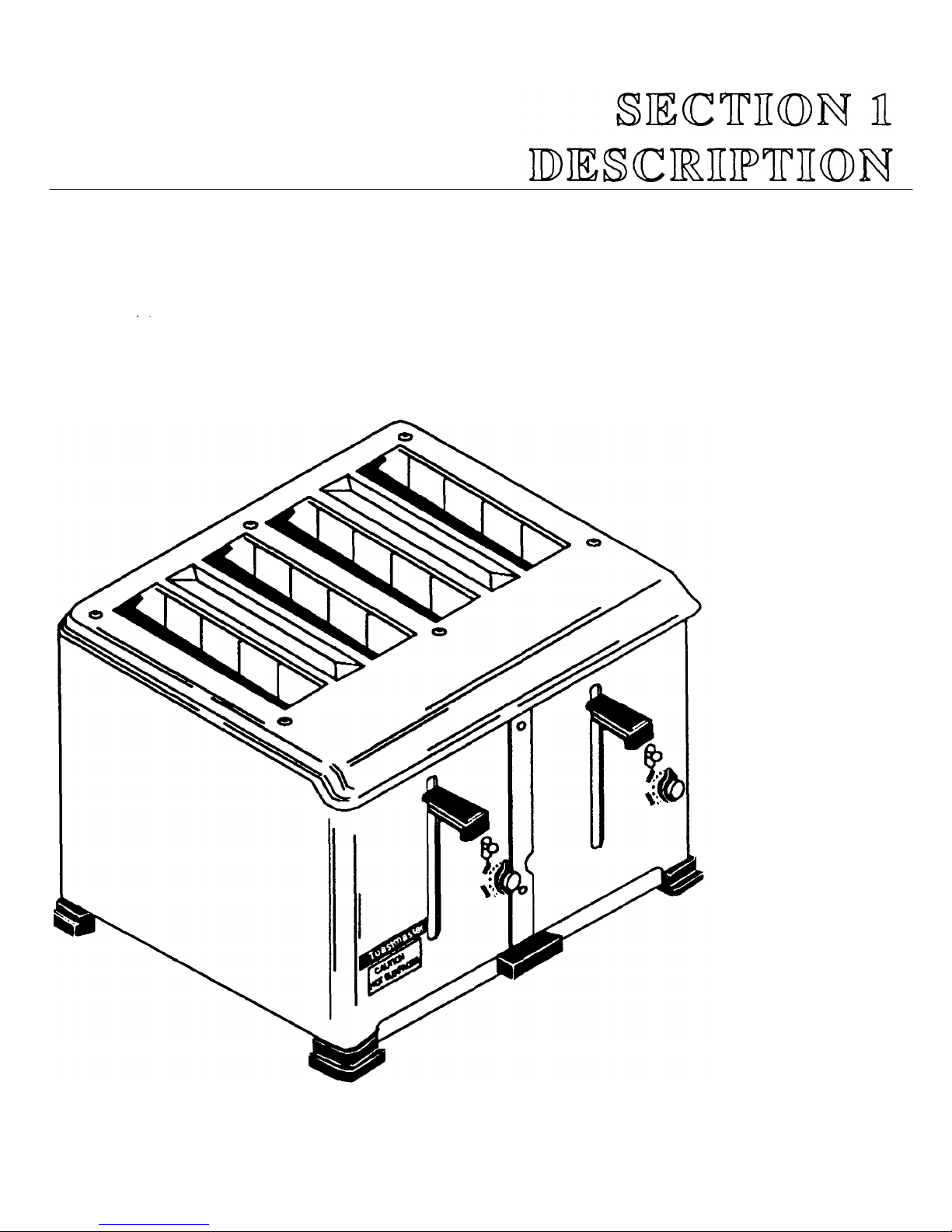
SECTION 1
DESCRIPTION
A Component Location
B Component Function
C Toaster Specifications
D Toaster Dimension Drawings
1
2
3
4
5-6
SECTION 2
INSTALLATION
B Unpacking Toaster
C Electrical Connection
D Checking the Installation
SECTION 3
OPERATION 9
A Location and Function of Controls
B Operating Procedure
C Operating Hints and Cautions
D Operating Capacity
E Cleaning
SECTION 4
PARTS LIST
Model 1D3 & 1 D2-2 Exploded Drawing
Model 1D22B& 1D3B Exploded Drawing
Model 1BB5 Exploded Drawing
SECTION 5
ELECTRICAL SCHEMATIC
Model 1D3 Schematic
Model 1D22B Schematic
Model 1BB5 Schematic
7
7
7
7
7
9
10
11
11
11
13
14-15
16-17
18-19
21
21
22
23
iii
Page 5
1
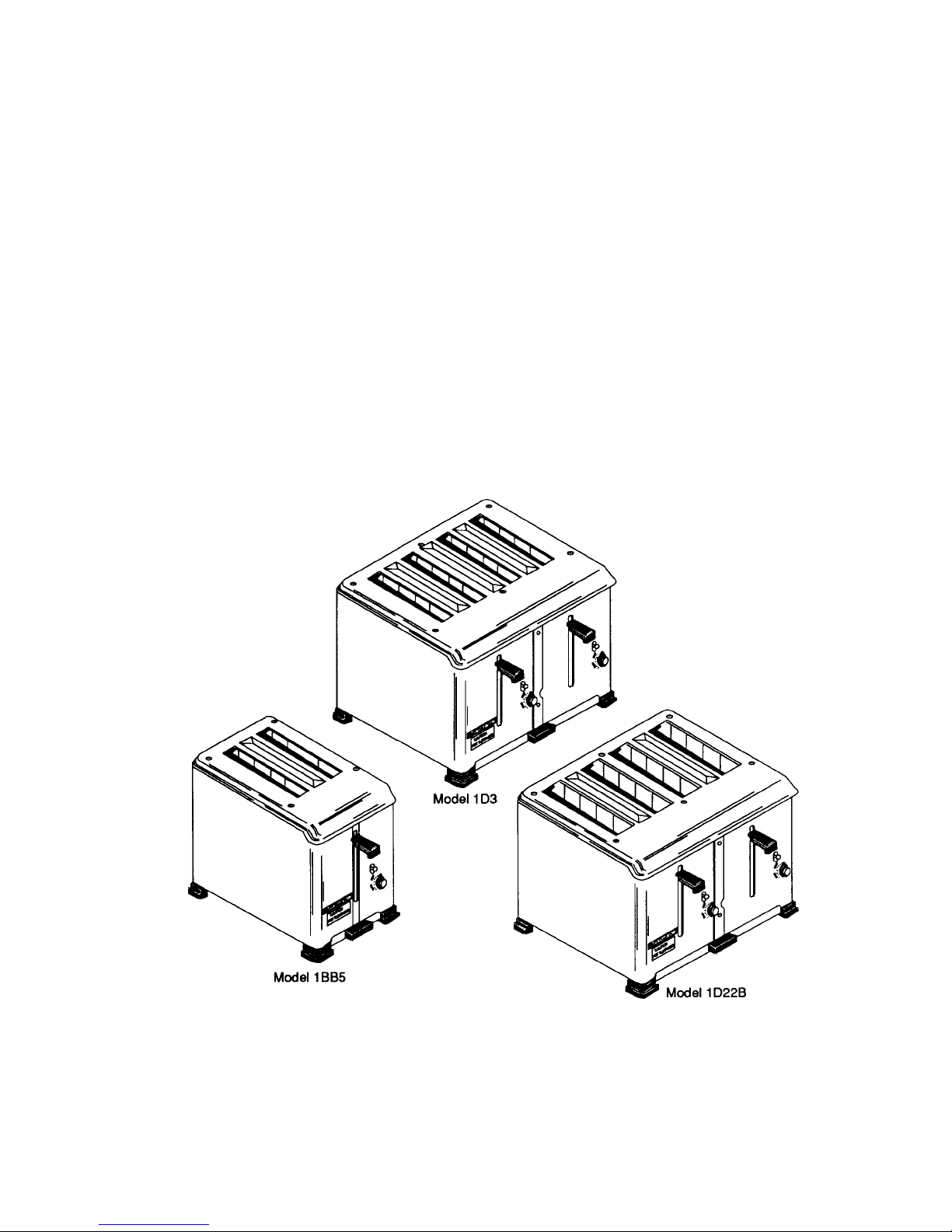
Toastmaster Model 1D3, 1D22B and 1BB5 Toasters are:
• Equipped with heating elements to provide uniform heat for even toasting.
• Automatic pop-up type toasters
• Equipped with an operating lever, color selection knob and manual release lever for each pair of toaster
• Equipped with wide slots. The Model 1 D22B bun toaster is equipped with extra wide slots.
• Timer controlled.
• Equipped with a crumb tray.
Figure 1-1
Page 6
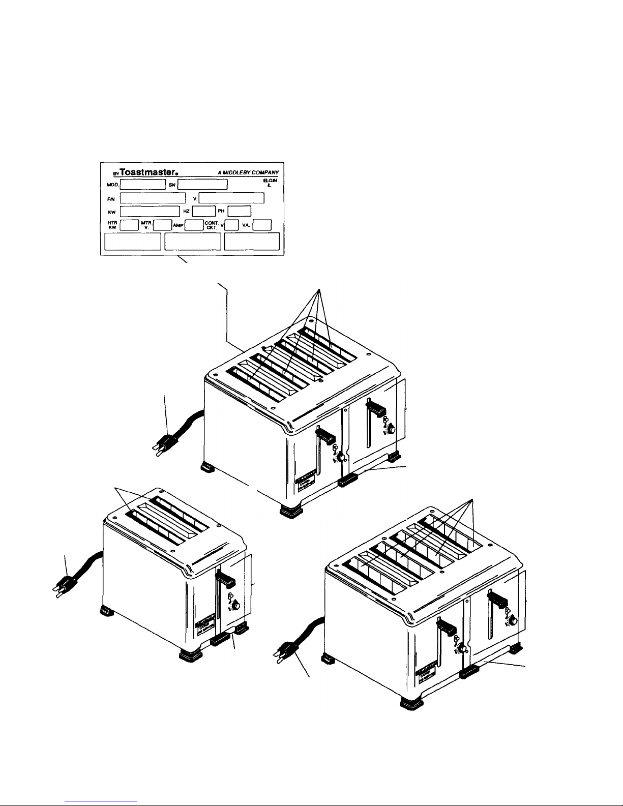
SECTION 1 - DESCRIPTION
Data Plate Located At
Slots
- Model 1D3 Has A Heating
Operating Controls (See
Crumb
36 "
Cord & Plug
36"
Cord
Crumb
Operating
Slots -
Model
1
BBS
Slots
-
Model 1D22B
Operating
36 " Cord
&
Plug
Figure 1
-2
A. Component Location
Has A Heating
Element on Both
Sides of Each Slot
&Plug
Rear Of Toasters
Element on Both Sides of Each Slot.
Model 1D3
Controls
(See
Operation
Section 3)
Operation Section 3)
Tray
Has A Heating Element
On Only One Side Of
Each Slot.
Controls
(See
Operation
Section 3)
2
Tray
Component Location
Crumb
Tray
Page 7

SECTION 1 - DESCRIPTION
B. Component Function
1. Slots
a. Model 1D3 Toaster has four slots for toasting one to four slices of bread. The width of the toasting
slots will accommodate "Texas Size" bread, frozen waffles, English muffins and many other food
items. A heating element is located on both sides of each slot for a total of 8 elements.
b. Model 1 BBS Toaster has two slots for toasting one or two slices of bread. The width of the toasting
slots will accommodate "Texas Size" bread, frozen waffles, English muffins and many other food
items. A heating element is located on both sides of each slot for a total of 4 elements.
c. Model 1 D22B is a bun toaster which has four extra wide slots for toasting one to four buns. The
toaster is equipped with an element on only one side of each of four slots for a total of four elements.
This allows toasting of buns on one side only.
2. Operating Controls
(Refer to Operation Section 3)
3. Crumb Tray
The crumb tray is located in the bottom of the toaster under all slots. The crumb tray is removed for
cleaning by pulling straight out from the front of the toaster.
3
Page 8

SECTION 1 - DESCRIPTION
Overall Dimensions
NOTICE
C. Toaster Specifications:
4
Toastmaster (Manufacturer) reserves the right to change specifications and product design
without notice. Such revisions do not entitle the buyer to corresponding changes, improve-
ments, additions or replacements for previously purchased equipment.
SPECIFICATION CHART
Model1D3 Model 1BB5 Model 1D22B
Width 11-5/8" (292mm) 6-1/2" (165mm) 11-5/8" (292mm)
x X x
Depth 13" (330mm) 12-9/16" (319mm) 13" (330mm)
x X x
Height 8-3/4" (222mm) 8-3/4" (222mm) 8-3/4" (222mm)
Toasting Slot Dimensions
Width 1-1/8" (29mm) wide 1-1/8" (29mm) wide 1-9/16" (40mm) wide
x x x
Length 5-1/4" (133mm) long 5-1/4" (133mm) long 5-1/4" (133mm) long
Approximate Net Weight 20 Ibs (9.1 kg) 13 Ibs (5.9 kg) 20 Ibs (9.1 kg)
Approximate Shipping Weight 25 IDS (11.3 kg) 15 Ibs (6.8 kg) 25 Ibs (11.3 kg)
Construction Formed & Welded Sheet Steel
Finish Chrome Steel
Capacity 4 slices/load, 2 slices/ load 4 bun halves/load
250 slices/hour 125 slices/hour 250/hour
Cord 36" (914mm) 36" (914mm) 36" (914mm)
Plug: Current NEMA6-15P NEMA5-15P NEMA5-20P
(208V & 240V) (120V) (120V)
Non-Current
NEMA14-20P NEMA6-15P NEMA6-15P
(120/208 V, 115/230 V (208V,230V & 240V) (208V,230V & 240V)
& 120/240V)
NEMA 14-20P
(120V, 120/208V,
115/230 V&120/240V)
Electrical: Current 208V(12.5Amp) 120V, 10.83 Amp 120V, 16.0 Amp,
240V (10.83 Amp), 2 Pole, 3 Wire 2 Pole, 3 Wire
2 Pole, 3 Wire
Non-Current 120/208 V, 120/240V, 208V (6.25 Amp), 120/208V, 120/240V,
10.83Amp/line, 240V (5.42 Amp), 8.0 Amp/line
3 Pole, 4 Wire 2 Pole, 3 Wire
208V, 4.62 Amp
240V, 4.0 Amp
2 Pole, 3 Wire
Page 9

D. Model 1D3 and 1D22B Toaster Dimension Drawings
1D22B
Top View
SECTION 1 - DESCRIPTION
1D3 and/or 1D22B mounted on 1D3CS Stand
1D3 TOD View
1D3 or 1D22B Front View
1D3 or 1D22B Side View
1D3 and/or 1D22B Dimension Drawings
Page 10

SECTION 1 - DESCRIPTION
6
D (continued). Model 1BB5 Toaster Dimension Drawing
Top View
Front View Side View
1BB5 Dimension Drawing
Page 11

A. Inspect for Shipping Damage
All shipping containers should be examined for damage before and during unloading. This equipment
was carefully inspected and packaged at the factory.
The freight carrier has assumed responsibility for its
safe transit and delivery. If equipment is received in
damaged condition, either apparent or concealed, a
claim must be made with the delivering carrier.
1. Apparent Damage or Loss - If damage or loss is
apparent it must be noted on the freight bill or
express receipt at the time of delivery, and it must
be signed by the earner's agent (driver). If this is not
done, the carrier may refuse the claim. The carrier
will supply the necessary claim forms.
CAUTION:
Before making any electrical connection be sure
the main electrical supply source Is turned "OFF".
C. Electrical Connection
All 1D3, 1BB5 and 1D22B toasters are factory
equipped with cord and plug. Do not change cord
and plug to fit existing receptacle. Proper receptacle
must be in place in accordance with local electrical
codes.
Refer to Specification Chart in Section 1 for plug
numbers.
2. Concealed Damage or Loss - If damage or loss is
NOT apparent until after equipment is unpacked, a
request for inspection of concealed damage must
be made with carrier within 15 days. The carrier will
make an inspection and will supply necessary claim
forms. Be certain to retain all contents plus external
and internal packaging materials for inspection.
B. Unpacking Toaster
1. Remove staples from carton.
2. Lift out foam packing and poly bag from around
toaster.
WARNING:
When handling toaster DO NOT stick your fingers
into slots as damage to heating
elements may result.
3. Lift toaster out of carton and set in place on
counter.
D. Checking the Installation
1. Turn main electrical supply source "ON".
2. Move Color Selector Knob to 9 o'clock position.
3. Lower operating lever.
4. Check if all toaster slots are heating. Check that
all heating elements are heating.
5. Lift manual release lever.
6. Check that all heating elements are no longer
heating.
7
Page 12

A. Location and Function of Controls
36 "
Cord & Plug
Operating
Manua
l Release
Color
Crumb Tray
The following information provides a basic description of the toaster controls, their location and the function they
perform. The operator must be familiar with the controls.
Lever
Lever
Selection
Knob
Figure 3-1
Operation Controls
(Model 1D3 shown. Models 1 BBS and 1 D22B operation control are basically the same as the Model 1 D3)
1. Operating Lever
Lowering the operating lever lowers the bread into the toasting chambers. When the toast has reached its
set darkness the operating lever and the toast will automatically be raised.
2. Color Selection Knob
Color selection knob is used to set the desired darkness of the toast.
3. Manual Release Lever
Manual release lever is used to manually raise the toast during the toasting cycle.
9
Page 13

SECTION 3 - OPERATION
B.
Operation Procedure
1. Insert bread into toaster slots.
IMPORTANT: On Model 1D22B bun toasters the buns must be inserted
so the side to be toasted faces the heating elements. The heating
elements are located as shown in Figure 3-2.
2. Positon color selection knob at desired darkness. A medium color
setting is 9 o'clock. Turn left for lighter toast and right for darker toast.
NOTE: It will be necessary to determine the color setting for each different
product you toast. Test a single piece at a 9 o'clock setting and then
increase or decrease as necessary.
3. Lower the operating lever to lower the bread into the toasting
chambers.
4. Wait for the completion of the cycle, and toast will automatically be
raised.
Side of bun to be toast ed must
face the heating element.
Heating elements are on the side
of the slots as shown.
10
1D22B Top View
Figure 3-2
Page 14

SECTION 3 - OPERATION
C. Operating Hints and Cautions
1. Toast Color
Experiment with the color selection knob so you can find the proper setting for the color you desire in your
toasted product.
2. Moisture In Bread
When toasting bread it is advisable to use one or two day old bread. Fresh bread contains more moisture
and is apt to toast unevenly.
3. Products to Toast
Use your Models 1 D3 and 1 BBS toasters for bread, texas toast, frozen waffles, English muffins and
similar items.
Use your Model 1 D22B toaster to toast buns (Toasts on one side only).
4. Clearing Jams
CAUTION! Disconnect electric power or unplug toaster before attempting to remove a toast jam.
CAUTION! DO NOT stick knives and forks Into the toasting chambers as you may damage the
heating elements, and cause electrical shock.
Use extreme caution to remove a toast jam. It is always better to wait for toaster to cool, if time permits,
before removing jammed toast. Unplug toaster before removing a toast jam.
5. Lifting Toaster
WARNING! DO NOT pick up the toaster by sticking fingers into toaster slots and grasping the
heating elements. Damage to the heating elements and electrical shock can result.
CAUTION! Always disconnect electrical power or unplug toaster before cleaning or performing any
service.
6. Service
Service MUST BE performed only by an authorized Toastmaster Service Agent.
D. Operation Capacity
The Model 1D3 will toast up to 250 slices/hour.
The Model 1BB5 will toast up to 125 slices/hour.
The Model 1D22B will toast up to 250 buns/hour.
E. Cleaning
CAUTION! Always disconnect electrical power or unplug toaster before cleaning or performing any
service.
1. Exterior
The exterior of your toaster may be kept clean by wiping with a sponge or cloth squeezed from hot or
warm detergent water. Wipe with clean, damp cloth to remove detergent and then wipe dry. DO NOT use
an abrasive cleaner or abrasive pads as it will scratch and dull the finish.
2. Crumb tray
The crumb tray should be removed and emptied daily. Wash crumb tray with warm detergent water and
rinse with clear water.
11
Page 15

SECTION 4 - PARTS LIST
ITEM#
QTY PART#
DESCRIPTION
9 4 1B6S61
MACHINE SCREW,
#8-32 x 1/4",
TRUSS HEAD
MODEL
1
D3 with cord
& 1
D2-2 without cord
14
Four Slice Bread Toasters
Figure 4-1
Overall Exploded Drawing
1 6 K1DS136 MACHINE SCREW, #10-32 x 1/4", TRUSS HEAD
2 1 K1DC42 CASE TOP
3 1 K1D85A CASE ASSEMBLY, COMPLETE
5 1 K1DC10 FRONT CASE BINDER
6 1 K1DC11 REAR CASE BINDER
7 4 K1 DS201 RIVET, 0.141x1/4"
8 1 2400075 TOASTMASTER NAME PLATE
Page 16

1
11 1
12 8
1
14 1
14
15 6
16 6
17 2
19 2 K1DS101
CUP BUSHING
2
21 1
22 2
23 4
24 4
25 4
26 1
27 1
28 1
29 1
2
31 2
32 4
33 2
34 2
35 2
36 2
37 2
38 2
39 2
40 2
41 2
42 4
43 2
44 4
45 4
46 16
47 12
48 8
49 16
50 16
51 16
8
52 8
53 8
54 8
* 2
55 2
56 2
57 2
58 8
59 2
60 2
61 4
62 2
63 2
* 2
* 2
64 2
65 2
66 2
67 2
68 2
* 2
69 2
70 2
71 1
72 4
SECTION 4 - PARTS LIST
10
13 1 3882D8735 1/2" CABLE CONNECTOR
14
18 1 K1DC40 JUMPER WIRE (208V, 230V & 240V TOASTERS ONLY)
20
30 2 K1DF20 OVEN RETAINER ASSEMBLY, FRONT OR REAR
•
52 8 K1D3917 ELEMENT ASSEMBLY 104V/325W FOR 208V TOASTERS (CURRENT)
52
K1DC32
K1DC39
1DS6
1D3S5
1D3S4
3001059
1DS29
K1DF140
141108821 MACHINE SCREW, #8-32 x 1", ROUND HEAD
3B82D8755 BRASS CUP WASHER, #8
K1D43
K1DF143
K1DS185
K1DS198
K1DS268
K1D92A
K1DS182
K1DS186
K1DF202
K1D47
K1DB46
K1AS20
K1D42
K1D40A1
K1D41
3B82D8809 SMALL HORSESHOE WASHER
K1 D46A
K1DS27
K1DF121
K1D52
B102851
1429A8817 MACHINE SCREW, #8-32 x 3/8", ROUNDHEAD
K1D48
K1D18010 OVEN & GUARD WIRE ASSEMBLY, RIGHT OR LEFT
K1DF102
E336A8803 STEEL HEX NUT, #5-40 x 1/4"
K1DS48
K1D116
K1DS111
K1DF165
K1DS47
K1D3922
K1D3922
K1D159
K1D158
K1D77B
K1C42B
1D3F25
K1DS209
K1DS195
K1D14610 VERTICAL ROLLER ASSEMBLY
K1DF116
K1DF175
K1DS213
K1D147
K1DF114
K1DS114
3562A15
8140804
K1DS181
K1DM4
K1DC30
K1DS206
K1D201
K1DF88
1D5B15
7002192
TERMINAL BOX COVER
TERMINAL BOX
MACHINE SCREW, #8-32 x 1/4", ROUND HEAD
CORD & PLUG, 250V (CURRENT)
CORD & PLUG, 125V/250V (4 WIRE, NON -CURRENT)
CORD & PLUG, 125V (3 WIRE, NON -CURRENT)
HEX NUT, BRASS, #8-32 x 11/32"
BRASS WASHER, 1/2" O.D. x 0.195 I.D.
TERMINAL PLATE ASSEMBLY
SPACER
THREAD CUTTING SCREW, #8-18 x 1/2", FLAT HEAD
ZYTEL FOOT
RUBBER FOOT INSERT
CRUMB PAN ASSEMBLY
DRAWER PULL CRUMB PAN HANDLE, ZYTEL
THREAD CUTTING SCREW, #5-40 x 3/8", PAN HEAD
GUIDE SHAFT RETAINER
SHOCK ABSORBER BRACKET & PISTON ASSEMBLY
BAFFLE PLATE
MACHINE SCREW, #5-40 x 1/8", ROUND HEAD
SHOCK ABSORBER CYLINDER & BRACKET ASSEMBLY
TRIP RELEASE BRACKET ASSEMBLY
TRIP RELEASE LEVER & SPRING ASSEMBLY
SHOCK ABSORBER PISTON & LINK ASSEMBLY
OPERATING SPRING LEVER
OPERATING LEVER ROLLER STUD
OPERATING LEVER ASSEMBLY
"E" RETAINING RING, 0.126"
THERMOSTAT, HOOK & BRACKET ASSEMBLY
CHANGE-OVER LINK, SHORT
ELEMENT POST INSU LATOR
TERMINAL POST & STRAP ASSEMBLY
BINDING POST SCREW, #5-40 x 7/16", PAN HEAD
BINDING POST NUT
ELEMENT CLIP INSULATOR
ELEMENT ASSEMBLY 120V/325W FOR 240V TOASTERS (CURRENT)
ELEMENT ASSEMBLY 120V/325W FOR 120/208V and 120/240V TOASTERS (NON-CURRENT)
REAR BINDING POST, UNKEYED
REAR BINDING POST, KEYED
SWITCH ASSEMBLY, COMPLETE, TWO POLE
STATIONARY SWITCH ASSEMBLY, TWO POLE
MOVEABLE SWITCH ASSEMBLY, TWO POLE
MACHINE SCREW, #5-40 x 5/16", S.S., ROUND HEAD, PRE-ASSEMBLED
MACHINE SCREW, #5-40 x 3/16", ROUND HEAD
HANDLE BRACKET STUD,SHORT
VERTICAL SHAFT
FRONT HANDLE SCREW, #6-32 x 1/4", PAN HEAD
HANDLE BRACKET ASSEMBLY
HANDLE BRACKET RELEASE CLIP
HANDLE BRACKET RELEASE CLIP STUD
OPERATING HANDLE, ZYTEL
TIMING BUTTON INSERT
TIMING BUTTON, ZYTEL
TIMER UNDERCOVER GUARD
MANUAL RELEASE STUD
TRIP RELEASE LEVER SPRING
TIMER ASSEMBLY
TIMER RETAINER BRACKET
TERMINAL BAFFLE
BREAD RACK, RIGHT OR LEFT (BREAD)
*PARTS NOT IDENTIFIED BY KEY NUMBERS
15
Page 17

SECTION 4 - PARTS LIST
2 1 K1DC34
CASE TOP, BUN
3 1 K1D85A
CAS
E ASSEMBLY, COMPLETE
5 1
K1DC10
FRONT CASE BINDER
6 1
K1DC11
REAR CASE BINDER
7 4
K1DS201
RIVET,
0.141
x
1/4" 8 1 2400075
TOASTMASTER NAMEPLATE
9 4 1B6S61
MACHINE SCREW,
#8-32 x 1/4",
TRUSS HEAD
MODEL 1D22B&1D3B
16
Bun Toaster
Parts List for Figure 4-2
Overall Exploded Drawing
ITEM QTY PART NO. DESCRIPTION
1 6 K1DS136 MACHINE SCREW, #10-32 x 1/4", TRUSS HEAD
Page 18

SECTION 4 - PARTS LIST
10 1 K1 DC32
TERMINAL BOX COVER
11 1
K1DC39
TERMINAL BOX
12 8
1DS6 MACHINE SCREW,
#8-32 x 1/4",
ROUND HEAD
13 1
3882D8735
1/2"
CABLE CONNECTOR
14 1 1D3S5
CORD
&
PLUG, 250V (CURRENT)
14 1 1D3S4
CORD
&
PLUG, 125V/250V
(4
WIRE, NO
N-CURRENT)
14 1 3001059
CORD
&
PLUG, 125V
(3
WIRE (NON
-
CURRENT)
15 6 1DS29
HEX NUT, BRASS,
#8-32 x 11/32"
16 6 K1DF140
BRASS WASH ER,
1/2"
O.D. x
0.195
I.D. 17 2 1411D8821
MACHINE SCREW,
#8-32
x 1", ROUND HEAD
18 1 K1DC40
JUMPER WIRE (208V, 230V
&
240
V TOASTERS ONLY)
19 2 K1DS101
CUP BUSHING
20 2
3B82D8755
BRASS CUP WASHER,
#8 21 1 K1D43
TERMINAL PLATE ASSEMBLY
22 2
K1DF143
SPACER
23 4
K1DS185
THREAD CUTTING SCREW,
#8-18 x 1/2",
FLAT HEAD
24 4
K1DS198
ZYTEL FOOT
25 4 K1DS268
RUBBER FOOT INSERT
26 1 K1D92A CRUMB PAN ASSEMBLY
27 1
K1DS182
DRAWER PULL CRUMB PAN HANDLE, ZYTEL
28 1
K1DS186
THREAD CUTTING SCREW,
#5-40 x 3/8",
PAN HEAD
29 1
K1DF202
GUIDE SHAFT RETAINER
30 2
K1DF20
OVEN RETAINER ASSEMBLY, FRONT OR REAR
• 2
K1D47
SHOCK ABSORBER BRAC
KET & PISTON ASSEMBLY
31 2 K1 DB46
BAFFLE PLATE
32 4
K1AS20
MACHINE SCREW,
#5-40 x 1/8",
ROUND HEAD
33 2
K1D42
SHOCK ABSORBER CYLINDER
&
BRACKET ASSEMBLY
34 2
K1D40A1
TRIP RELEASE BRACKET ASSEMBLY
35 2
K1D41
TRIP RELEASE LEVER
&
SPRING ASSEMBLY
36 2
3B82D8809
SMALL HORSESHOE WASHER
37 2 K1 D46A
SHOCK ABSORBER PISTON
&
LINK ASSEMBLY
38 2
K1DS27
OPERATING SPRING LEVER
39 2
K1DF121
OPERATING LEVER ROLLER STUD
40 2
K1D52
OPERATING LEVER ASSEMBLY
41 2 B102851
"E" RETAINING RING,
0.126"
42 4
1429A8817
MACHINE SCREW,
#8-32 x 3/8",
ROUND HEAD
43 2
K1D48
THERMOSTAT, HOOK
&
BRACKET ASSEMBLY
44 2 K1D180
OVEN
&
GUARD WIRE ASSEMBLY (RIGHT)
44 2 K1D181
OVEN
&
GUARD WIRE ASSEMBLY (LEFT)
45 4
K1DF102
CHANGE
-
OVER LINK, SHORT
46 8
E336A8803
STEEL HEX NUT,
#5-40 x 1/4" 47 4 K1
DS48
ELEMENT POST INSULATOR
49 8
K1DS111
BINDING POST SCREW,
#5-40 x 7/16",
PAN HEAD
50 8
K1DF165
BINDING POST NUT
51 8
K1DS47
ELEMENT CLIP INSULATOR
52 4 K1
D3923
ELEMENT ASSEMBLY 120V, 480W FOR 120V TOASTERS (CURRENT)
52 4 K1D3918
ELEMENT ASSEMBLY 104V,
480W
FOR 208V TOASTERS (NON
-
CURRENT)
52 4
K1D3923
ELEMENT ASSEMBLY 120V,
480W
FOR 240V, 120/208V and 120/240V TOASTERS (NON
-
CURRENT)
53 4 K1D159
REAR BINDING POST, UNKEYED
54 4 K1D158
REAR BINDING POST, KEYED
* 2 K1D77B
SWITCH AS
SEMBLY, COMPLETE, TWO POLE
55 2
K1C42B
STATIONARY SWITCH ASSEMBLY, TWO POLE
56 2
1D3F25
MOVEABLE SWITCH ASSEMBLY, TWO POLE
57 2 K1
DS209
MACHINE SCREW,
#5-40 x 5/16",
S.S., ROUND HEAD PRE
-
ASSEMBLED
58 8 K1DS195
MACHINE SCREW,
#5-40 x 3/16",
ROUND HEAD
59 2
1D3B146
VERTICAL ROLLER ASSEMBLY
60 2
K1DF116
HANDLE BRACKET STUD, SHORT
61 4
K1DF175
VERTICAL SHAFT
62 2
K1DS213
FRONT HANDLE SCREW,
#6-32 x 1/4",
PAN HEAD
63 2
1D3B147
HANDLE BRACKET ASSEMBLY
* 2
K1DF114
HANDLE BRACKET RELEASE CLIP
* 2 K1DS114
HANDLE BRACKET RELEASE CLIP STUD
64 2 3562A15
OPERATING HANDLE, ZYTEL
65 2 B 140804
TIMING BUTTON INSERT
66 2 K1DS181
TIMING BUTTON, ZYTEL
67 2
K1DM4
TIMER UNDERCOVER GUARD
68 2
K1DC30
MANUAL RELEASE STUD
* 2 K1DS206
TRIP RELEASE LEVER SPRING
69 2
K1D201
TIMER ASSEMBLY
70 2
K1DF88
TIMER RETAINER BRACKET
71 1 1D5B15
TERMINAL BAFFLE
72 2
K1D170
BREAD RACK, RIGHT (BUN)
73 2
K1D171
BREAD RACK, LEFT (BUN)
*PARTS NOT IDENTIFIED BY KEY NUMBERS
17
Page 19

SECTION 4 - PARTS LIST
18
Figure
4-3
1 6 K1DS136
MACHINE SCREW,
#10-32 x 1/4",
TRUSS HEAD
2 1 S1BC2
CASE TOP, BREAD
3 1 1BB510
CASE ASSEMBLY
4 1 1523B3029
TOASTM
ASTER NAMEPLATE
5 1 1BB5B3
TERMINAL BAFFLE
6 1
1BB526
CORD TERMINAL
&
INSULATOR ASSEMBLY
7 2 1B12S60
TUBULAR STEEL RIVET, .118/.123 x
5/32
- 8 2 K1DS195
SCREW,
#5-40 x 1/4",
PAN HEAD, STAINLESS STEEL
MODEL1BB5
Two Slice Bread Toaster
Overall Exploded Drawing
ITEM
QTY
PART NO. DESCRIPTION
Page 20

1
1
1
1
1
1
1
1
1
9 2 K1AF17 BRASS WASHER. .128 I.D. x .308 O.D. x 1/32"
10 1 K1DS111 SEMS SCREW, PRE-ASSEMBLED, #5-40 x 1/2-, PAN HEAD
11 2 S1BC8 CABLE STRAIN RELIEF
12 1 1BB5C4 STRAIN RELIEF BOX
13 1 1511E8705 CORD & PLUG, 125V (CURRENT)
13 1 1BB5S4 CORD & PLUG, 250V (NON-CURRENT)
14 4 K1AS20 SCREW. #5-40 x 1/8-, ROUND HEAD
15 1 S1BF22 GUIDE SHAFT BRACKET
16 2 K1DS185 THREAD CUTTING SCREW, #8-18 x 1/2". FLAT HEAD
17 4 K1DS198 ZYTEL FOOT
18 1 K1DS186 THREAD CUTTING SCREW, #5-40 x 3/8", PAN HEAD
19 1 S1B3A CRUMB PAN
20 1 K1DS182 DRAWER PULL HANDLE, ZYTEL
21 4 K1DS228 RUBBER FOOT INSERT
22 1 K1DS12 #8 LOCKWASHER
23 1 K1D52 OPERATING LEVER ASSEMBLY
24 1 K1D48 THERMOSTAT HOOK & BRACKET ASSEMBLY
25 1 B102851 "E" RETAINING RING, #5144-9
26 1 1429A8827 HEX STEEL NUT, #8-32
27 1 K1DS115 PISTON RING
28 1 K1 DS27 OPERATING LEVER SPRING
29 1 K1DF121 OPERATING LEVER ROLLER STUD
30 1 K1D46A SHOCK ABSORBER PISTON & LINK ASSEMBLY
31 1 K1 DB54 BAFFLE PLATE
32 1 K1D42 SHOCK ABSORBER CYLINDER & BRACKET ASSEMBLY
33 1 K1D40A1 TRIP RELEASE BRACKET ASSEMBLY
34 1 K1D41 TRIP RELEASE LEVER & SPRING ASSEMBLY
35 2 1429A8817 SCREW, #8-32 x 3/8", ROUND HEAD
36 1 B112811 •E" RETAINING RING, #5144-18
• 1 K1D77B SWITCH ASSEMBLY, TWO POLE
37 1 K1C42B STATIONARY SWITCH ASSEMBLY, TWO POLE
38 1 1D3F25 MOVEABLE SWITCH ASSEMBLY, TWO POLE
39 1 K1DS209 MACHINE SCREW, PRE-ASSEMBLED, #5-40 x 5/16", ROUND HEAD, S.S.
40 2 7002192 BREAD RACK, RIGHT OR LEFT
41 1 K1D146A VERTICAL ROLLER ASSEMBLY WITH BREAD RACKS
42 1 K1DF116 HANDLE BRACKET STUD,SHORT
43 1 K1D147 HANDLE BRACKET ASSEMBLY (Refer to Item 47 for RELEASE CLIP)
44 1 K1DS206 SWITCH TENSION SPRING
45
46
47
*
48
49
50
51
52
53 2 K1DF175 VERTICAL SHAFT
54 2 K1D18010 OVEN & GUARD WIRE ASSEMBLY (RIGHT OR LEFT)
55 4 K1D3922 ELEMENT ASSEMBLY 120V, 325W FOR 120V TOASTERS (CURRENT)
55 4 K1D3922 ELEMENT ASSEMBLY 120V, 325W FOR 240V TOASTERS (NON-CURRENT)
55 4 K1D3917 ELEMENT ASSEMBLY 104V, 325W FOR 208V TOASTERS (NON-CURRENT)
56 4 K1D158 REAR BINDING POST, UNKEYED
57 4 K1D159 REAR BINDING POST, KEYED
58 2 K1DF102 CHANGEOVER LINK, SHORT
59 8 K1DS47 ELEMENT CLIP INSULATOR
60 1 K1DS206 TRIP RELEASE LEVER SPRING
61 8 K1DF165 BINDING POST NUT
62 4 K1D116 TERMINAL POST & STRAP ASSEMBLY
63 8 E336A8803 STEEL HEX NUT, #5-40x1/4"
64 4 K1DS48 ELEMENT POST INSULATOR
* 2 K1DF200 OVEN RETAINER, FRONT OR REAR
*PARTS NOT IDENTIFIED BY KEY NUMBERS
K1DS213 SCREW, #6-32 x 1/4", PAN HEAD
3562A15 ZYTEL HANDLE
K1DF114 HANDLE BRACKET RELEASE CLIP
K1DS114 HANDLE BRACKET RELEASE CLIP STUD
K1DM4 TIMER UNDERCOVER GUARD
K1DF88 TIMER RETAINER BRACKET
K1D201 TIMER ASSEMBLY
K1DC30 MANUAL RELEASE STUD
K1DS181 TIMING BUTTON, ZYTEL
SECTION 4 - PARTS LIST
19
Page 21

Current
Cord w/NEMA
6-1
5P Plug used with
6
-
Heating
Cord w/NEMA 14
-
20P Plug used
Neutral
Heating
208V and 240V
2 Pole, 3 Wire
Heat Switch Heat Switch
15R Receptacle, #16-3 AWG at least
90°C (194°F)
Elements
Non-Current 1
20/208V, 115/230V and 120/240V
3 Pole, 4 Wire
.
Heat Switch Heat Switch
with 14-20R Receptacle, #14-4
AWG at least 90°C (194°F)
Elements
Model 1D3 Schematics
21
Page 22

SECTION 5 - SCHEMATICS
Cord w/NEMA 5
-
20P Plug used
Heating
Cord w/NEMA
6-1
5P Plug used
Heating
Non-Current 120/208V, 115/230V
and 120/240V 3 Pole, 4 Wire
Cord w/NEMA 14-20P Plug used
with 14-20R Receptacle, #14-4
AWG at least 90°C (194°F)
Neutral
Current
120V
2 Pole, 3 Wire
Neutral
Heat Switch Heat Switch
Non-Current
208V and 240V
2 Pole, 3 Wire
Heat Switch Heat Switch
with 6-15R Receptacle, #16-3 AWG
with 5-20R Recept acle, #14-3
AWG at least 90°C (194°F)
Elements
at least 90°C (194°F)
Elements
22
Model 1D22B Schematics
Page 23

Current
Cord w/NEMA
5-1
5P Plug used
Heating
23
120V
2 Pole, 3 Wire
Heat Switch
SECTION 5 - SCHEMATICS
with 5-15R Receptacle, #16-3
AWG at least 90°C (194°F)
Elements
Non-Current
208V and 240V
2 Pole, 3 Wire
Cord w/NEMA 6-15P Plug used
with 6-15R Receptacle, #16-3
AWG at least 90°C (194°F)
Heat Switch
Model 1BB5 Schematics
Heating
Elements
 Loading...