

Page 1
INSTRUCTION MANUAL
COLOR DOME CAMERA C-CV202-3 CU
Thank you for purchasing TOA's Color Dome Camera.
Please carefully follow the instructions in this manual in order to ensure long, trouble-free use of your color dome camera.
1. SAFETY PRECAUTIONS
• Before installation or use, be sure to carefully read all the instructions in this section for correct and safe operation.
• Make sure to observe the instructions in this manual as the conventions of safety symbols and messages regarded as very important
precautions are included.
• We also recommend you keep this instruction manual handy for future reference.
• Use the unit only with the voltage specified on the unit. Using a
voltage higher than that which is specified may result in fire or
electric shock.
• Use screws and bolts that are appropriate for the ceiling's or wall's
structure and composition. Failure to do so may cause the unit to fall,
resulting in material damage and possible personal injury.
• Install the unit only in a location that can structurally support the
weight of the unit and the mounting bracket. Doing otherwise may
result in the unit falling down and causing personal injury and/ or
property damage.
• Do not install the unit outdoors since it is designed for indoor use. If
installed outdoors, the aging of parts causes the unit to fall down,
possibly resulting in personal injury. Also, when it is exposed to rain,
an electric shock may result.
• To prevent a fire or electric shock, never open the unit case nor
modify the unit as there are high voltage components inside the unit.
Refer all servicing to your nearest TOA dealer.
• Should any of the following irregularity be found during use,
disconnect the power supply and contact your TOA dealer. Do not
attempt to further use the unit because a fire or electric shock may
result.
· If you detect smoke or a strange smell coming form the unit
· If water or any metallic object gets into the unit
· If the unit falls, or the unit case breaks
· If the power supply cord is damaged (exposure of the core,
disconnection, etc.)
· If no image appears
• Do not insert nor drop metallic objects or flammable materials in the
ventilation slots of the unit's cover, as this may result in fire or electric
shock.
• Have the unit periodically checked by the dealer from where it was
purchased. Should the unit or its mounts corrode or structurally
deteriorate, the unit could fall down, possibly resulting in personal
injury.
• Avoid installing the unit in humid or dusty locations, in locations
exposed to the direct sunlight, near the heaters, or in locations
generating sooty smoke or steam as doing otherwise may result in
fire or electric shock.
• Note correct polarity (positive and negative orientation) when
connecting the power supply cable. Incorrect connection may cause
failure of other equipment connected.
• Leave the installation of the unit to your TOA dealer because the
installation requires expert experience and skills. If the unit falls, this
could cause personal injuries.
• Do not hang down from the camera as this may cause it to fall down
or drop, resulting in personal injury and/ or property damage.
• Disconnect the power supply, and unplug the power supply plug from
the AC outlet for the safety purposes when cleaning or leaving the
unit unused for long periods of time. Doing otherwise may cause a
fire or electric shock.
Indicates a potentially hazardous situation which, if mishandled, could
result in moderate or minor personal injury, and/or property damage.
CAUTION
Indicates a potentially hazardous situation which, if mishandled,
could result in death or serious personal injury.
WARNING
Do not expose the unit to rain or an environment where it may be
splashed by water or other liquids, as doing so may result in fire or
electric shock.
WARNING
CU version complies with Part 15 of the FCC Rules.
This device complies with Part 15 of the FCC Rules. Operation is
subject to the following two conditions: (1) this device may not
cause harmful interference, and (2) this device must accept any
interference received, including interference that may cause
undesired operation.
Note
This equipment has been tested and found to comply with the
limits for a Class B digital device, pursuant to Part 15 of the FCC
Rules. These limits are designed to provide reasonable protection
against harmful interference in a residential installation. This
equipment generates, uses and can radiate radio frequency
energy and, if not installed and used in accordance with the
instructions, may cause harmful interference to radio
communications. However, there is no guarantee that
interference will not occur in a particular installation. If this
equipment does cause harmful interference to radio or television
reception, which can be determined by turning the equipment off
and on, the user is encouraged to try to correct the interference
by one or more of the following measures:
• Reorient or relocate the receiving antenna.
• Increase the separation between the equipment and receiver.
• Connect the equipment into an outlet on a circuit different from
that to which the receiver is connected.
• Consult the dealer or an experienced radio/ TV technician for
help.
Modifications
Any modifications made to this device that are not approved by
TOA Corporation may void the authority granted to the user by
the FCC to operate this equipment.
This Class B digital apparatus compliance with Canadian ICES-
003.
Cet appareil numérique de la classe B est conforme à la norme
NMB-003 du Canada.
Page 2
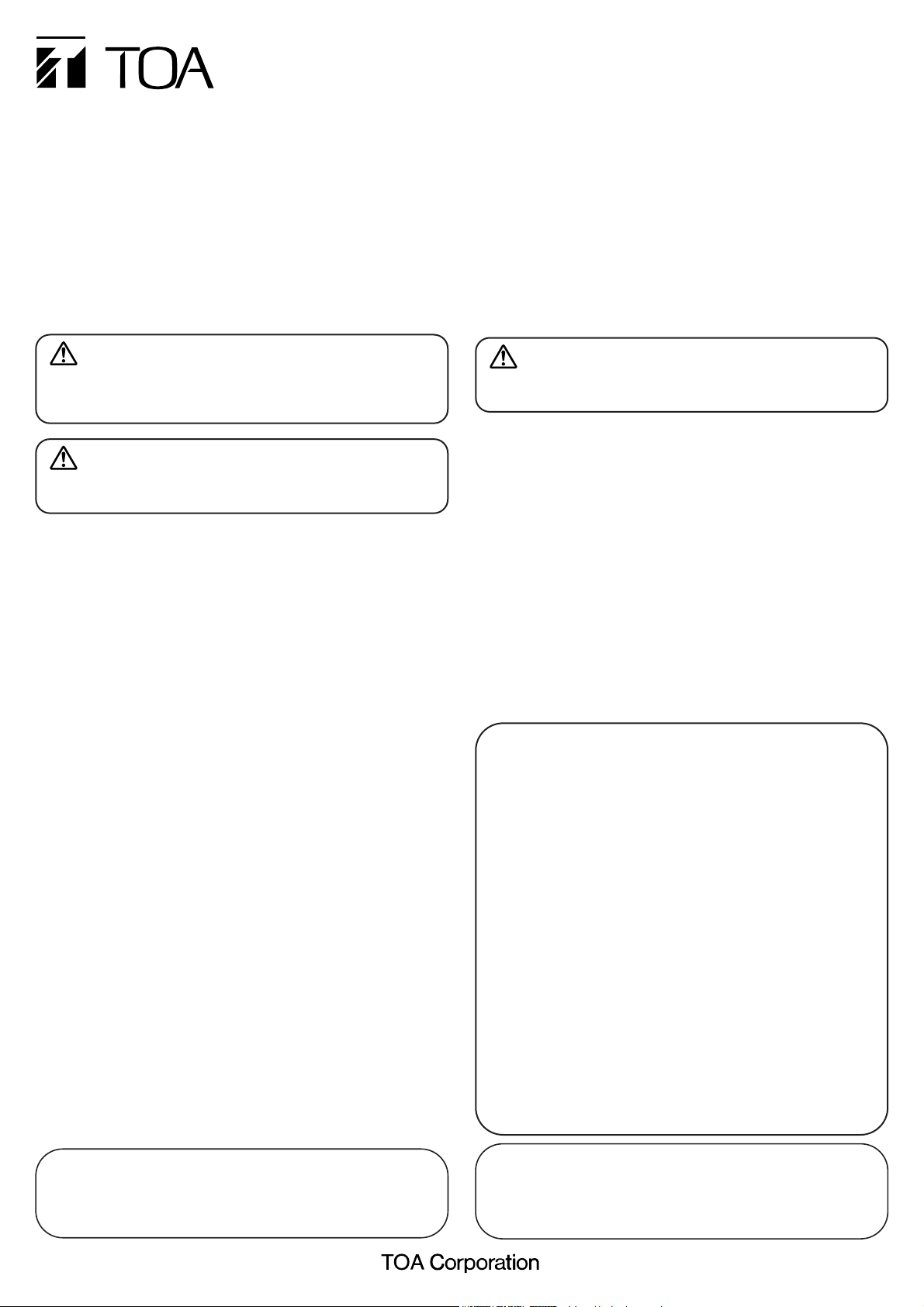
[
bottom view
]
(1) Power Input cable (12 V DC)
(2) Video output terminal (BNC-R jack)
(3) Monitor output terminal (RCA pin jack)
(4) Mode setting switch
(5) Iris control
(6) Dome cover
[
side view of the camera with a dome cover
]
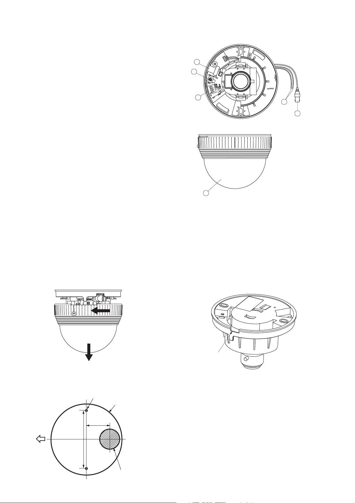
1. Detach the dome cover.
Turn the dome cover counterclockwise to detach from the camera
section.
2. Determine the wiring method.
2-1. Unexposed wiring
Make a cable entry hole in the ceiling.
2-2. Open wiring
Cut out the thin camera section shown below using a pair of
nippers.
3. Connect the coaxial cable to the Video output terminal, and the
power supply cable to the power input cable.
Match the polarities when connecting the power supply cable to the
power input cable.
The red cable of the power input cable is positive, while the black
one of that is negative.
Apply a self adhesive insulating tape both at the power supply cable
connection with the power input cable, and BNC connection.
3. HANDLING PRECAUTIONS
• Do not direct the camera lens to the sun or strong lighting or light
reflection.
• Do not give the camera a great shocks or vibration, as this will
damage the camera.
• It is recommended that the camera be always used in locations
where the ambient temperature ranges from -10°C to +50°C and
humidity levels of less than 90% to ensure that no condensation is
formed.
• To clean, wipe with a dry soft cloth. Never use benzene, thinner or
chemically processed towel as the unit's plastic or other parts may be
deformed or discolored.
• When dust has settled on the camera's lens, lightly clean using a
commercial camera blower or cleaning paper.
• Installing the camera cables in close proximity to fluorescent lamps
or other electrical appliances can downgrade the picture quality. In
such cases, change the wiring.
• If there is a strong electric or magnetic field near the camera, such as
television transmission antennas, motors or transformers, this may
distort or roll the monitor picture. In such cases, run the entire wiring
route through metal conduit tubing.
• Do not install the camera in locations where solvents or chemicals
are used as the camera's dome cover may be deformed or
discolored.
• Use the external power supply unit of the following rating.
12 V DC, over 0.5 A
4. NOMENCLATURE
5. INSTALLATION
2. GENERAL DESCRIPTION
The C-CV202-3 Color Dome Camera is an indoor-use camera and is
equipped with a high-resolution camera and lens. It is designed to
operate on 12 V DC, which is supplied by an external power supply
unit. Since its 2X vari-focal, auto-iris lens is built inside the camera, its
angle of view can be manually adjusted.
3
5
4
6
1
2
Camera mounting hole
Camera outside diameter
ø105 mm
35 mm
Cut out using
a pair of nippers.
Camera direction
83.5 mm
Cable entry hole
ø25 mm
Page 3

4. Mount the camera section to the ceiling using 2 mounting screws.
Because the mounting screws are not supplied with the camera,
prepare appropriate screws for the application. (Use screws that
are over 4 mm in nominal diameter and longer than 25 mm.)
5. Attach the dome cover to the camera section after completing all
necessary adjustments.
Insert the dome cover to the camera section, then turn it clockwise
until it locks into place.
After attaching the dome cover, fit it using a supplied dome cover
fixing screw.
When detaching the dome cover, first remove the screw, then
detach the dome cover.
Note
Do not forcefully tighten the screw. Extreme force is applied to the
screw and the screw could not be removed, as this may cause the
dome cover not to become detached.
1. Switch on the power supply of 12 V DC after completing camera
connections.
The power is supplied to the camera.
2. Connect the monitor to the Monitor Output terminal to permit a
picture to be viewed on the monitor.
Note
When the monitor output terminal is connected, a video signal
cannot be output to the video output terminal.
3. Set the Shutter Speed switch to ON if light flicker is annoying.
Light flicker may interfere with the view under fluorescent lamps in
the area where power frequency is 50 Hz. In such cases, set the
Shutter Speed switch to "ON" position, and the image free from
flickering can be obtained.
Note
If the Shutter Speed switch is set to the ON position, sensitivity is
reduced compared to operation in the OFF position. When using
the camera in a dark location, or where light flicker is not an
annoyance, set the switch to the OFF position.
4. Adjust the camera angle.
Camera angle can be adjusted for up to 60°(± 30°) for horizontal
rotation, and between 0 °and 70° for vertical rotation.
5. Adjust the angle of view with the Zoom ring and adjust the focus
with the Focus ring for the best possible picture reproduction. After
lens adjustment completion, tighten both the Zoom ring fixing screw
and the Focus ring fixing screw.
Notes
• Since the Iris control (for sensitivity adjustment) is factory-preset to
an optimum position for general use, avoid tampering with it in
normal conditions. Turning the control unnecessarily could cause
reduced picture quality or equipment failure. When the Iris control
needs to be readjusted to match a specific subject, first set both the
Adjustment switch and the Backlight Compensation switch to the
OFF position, then adjust the control to an optimum level. After
adjustment, place a hand over the lens for several seconds and then
release to check the lens for correct iris operation.
• If the focus is adjusted for a subject under good lighting conditions,
the subject may go out of focus when conditions become dark. To
avoid this, adjust the lens focus after setting the Adjustment switch to
the ON position. Be sure to switch it back to the OFF position after
completing lens adjustment.
Note
If the Video output is not terminated at 75 Ω, video pictures are not
properly displayed. Make sure that the output has been terminated at
75 Ω at the connected monitor or switcher.
6. ADJUSTMENT
7. CONNECTIONS
Attach the dome cover
with its projection aligned
with the mounting hole of
the camera section.
Dome cover fixing screw
(accessory)
Camera direction
Mounting screw
Horizontal rotation ± 30°
Focus ring
Vertical rotation between
Zoom ring
Zoom ring
fixing screw
0° and 70°
Focus ring
fixing screw
Video output
Use the external power supply unit
of the following rating.
12 V DC, over 0.5 A
Match the polarity of the power supply
cable with that of the power input cable
-
(+,
Video input
BNC
Power supply of 12 V DC
) when connecting.
Monitor
Page 4

133-22-004-9A
Standard position:
Set to OFF after lens adjustment completion. Set to this
position during normal use.
Adjustment position (during adjustment):
Use this position when focusing the lens. If the focus is
adjusted for a subject under good lighting conditions,
the subject may go out of focus when conditions
become dark. Set the Adjustment switch to ON only
when performing focus adjustment.
Note
The color of the screen may periodically vary under
fluorescent lighting when the Adjustment switch is set
to ON. Light flicker may interfere with the view in the
area where power frequency is 50Hz.
Adjustment (ALC/ AES) switch
Set this switch when adjusting the lens focus.
ATW:
Set to this position during normal use. The camera's
white balance automatically changes as an object's
color temperature varies.
AWB:
Use this switch when the difference between the
displayed color and actual color is annoying. Shoot the
white object, then turn the switch ON. The camera
operates on the initially-set white balance even if an
object's color temperature changes.
Standard position:
Set to this position during normal use. Backlight
Compensation function does not operate when the
switch is set to this position.
Backlight Compensation position (when backlit):
This position compensates images from being
displayed in black when the image is backlit.
Standard position:
Set to this position during normal use.
Shutter Speed position:
Annoying screen flicker may result under fluorescent
lighting in areas operating with a power frequency of 50
Hz. In such cases, set the Shutter Speed switch to the
ON position to permit a flicker-free picture to be viewed.
Note
If the Shutter Speed switch is set to the ON position,
sensitivity is reduced compared to operation in the OFF
position. When using the camera in a dark location, or
where light flicker is not an annoyance, set the switch
to the OFF position.
12 V DC ±10%
1.5 W (120 mA
)
1/4 Type IT-CCD
768 (H)x 494 (V)(380,000 pixels
)
2:1 interlace
Horizontal: 15.734 kHz, Vertical: 59.94 Hz
VBS1.0 V(p-p), 75 Ω, RCA pin jack
VBS1.0 V(p-p), 75 Ω, BNC-R jack
Internal synchronization
Horizontal: 480 lines (at center)
Vertical: 350 lines (at center)
50 dB
8 lx (50 IRE), 2 lx (20 IRE
)
ATW/ AWB
f=2.8 mm
-
5.8 mm
Power Source
Power Consumption
Image Device
Number of Effective
Pixels
Scanning System
Scanning Frequency
Monitor output
Video Output
Synchronizing System
Resolution
S/ N Ratio
Minimum Illumination
White Balance Mode
Focal length
Note
The design and specifications are subject to change without notice for
improvement.
ATW/ AWB switch
Set the white balance operation.
Backlight Compensation (BLC) switch
Set this switch so that the subject is not displayed in black when
backlit.
Shutter Speed switch
Set this switch to the ON position when annoying screen image flicker
is detected.
1:1.4 - 1.8
Auto-iris
Horizontal: 76.7°-38.3°
Vertical: 56.8°-28.7°
ON/ OFF (used for focus adjustment
)
Backlight compensation, Shutter speed
(
1/60, 1/100), Iris control
-
10°C to + 50°C
Under 90% RH (no condensation
)
Indoor use
Case: ABS resin, cool gray
Dome cover: Acrylic resin, smoked
ø107 x 78.7 (h)mm
170 g
Maximum Aperture
Ratio
Iris
Angle of view
Adjustment Switch
Other Functions
Operating Temperature
Operating Humidity
Applications
Finish
Dimensions
Weight
8. ABOUT THE MODE SETTING SWITCH
Set the Mode Setting switch for the best possible picture reproduction depending on installation conditions.
9. SPECIFICATIONS
• Accessory
Dome cover fixing screw (2.6 x 8).................... 1
ON
ON
OFF
1 2 3 4
Mode Setting switch
(Factory-preset setting)
1. Adjustment (ALC/ AES) switch
2. ATW/ AWB switch
3. Backlight Compensation (BLC) switch
4. Shutter Speed switch
ON
1 2 3 4
ON
1 2 3 4
ON
1 2 3 4
ON
1 2 3 4
ON
1 2 3 4
ON
1 2 3 4
ON
1 2 3 4
ON
1 2 3 4
 Loading...