

Page 1
REV. A 4/00
TJERNLUND PRODUCTS, INC.
1601 Ninth Street • White Bear Lake, MN 55110-6794
PHONE (800) 255-4208 • (651) 426-2993 • FAX (651) 426-9547
Visit our web site • www.tjernlund.com
MODEL
MAC-4
MULTIPLE APPLIANCE CONTROL
For Interlocking Power Venters, Draft Inducers
IN-FORCERS or Dampers with up to four burners
TABLE OF CONTENTS
Cautions ..........................................................................................................................................................................1
Electrical Wiring
Electrical Specifications & Circuit Board Features .....................................................................................................1
Wiring to 24V Gas Equipment ...............................................................................................................................2, 3
Wiring to 115V Gas Equipment ..............................................................................................................................4, 5
Wiring to Millivolt Gas Equipment ..............................................................................................................................6
Wiring to Oil Equipment .....................................................................................................................................6, 7, 8
Safety Interlock Test ........................................................................................................................................................9
Replacement Parts & Warranty .......................................................................................................................................9
DESCRIPTION
The MAC-4 is used for wiring up to 4 heating appliances with Draft Inducers, Power Venters, IN-FORCERs or 115V Dampers. It is
suitable for any combination of 24 VAC and 115 VAC control systems for gas and oil burners.
OWNER INSTRUCTIONS, DO NOT DESTROY
!
Recognize this symbol as an indication of important Safety Information!
THESE INSTRUCTIONS ARE INTENDED AS AN AID TO QUALIFIED, LICENSED
SERVICE PERSONNEL FOR PROPER INSTALLATION, ADJUSTMENT AND
OPERATION OF THIS UNIT. READ THESE INSTRUCTIONS THOROUGHLY
BEFORE ATTEMPTING INSTALLATION OR OPERATION. FAILURE TO FOLLOW
THESE INSTRUCTIONS MAY RESULT IN IMPROPER INSTALLATION, ADJUSTMENT, SERVICE OR MAINTENANCE POSSIBLY RESULTING IN FIRE, ELECTRI CAL SHOCK, CARBON MONOXIDE POISONING, EXPLOSION, OR PERSONAL
INJURY OR PROPERTY DAMAGE.
PLEASE READ CAREFULLY AND KEEP ON JOB
SITE FOR FUTURE REFERENCE.
Copyright © 2000, Tjernlund Products, Inc. All rights reserved. P/N 8504088
Page 2

CAUTIONS
1. Failure to install, maintain and/or operate the MAC-4 in accordance with manufacturer’s instructions may result in conditions that
can produce bodily injury and property damage.
2. The safety interlock and system operation performance checks must be performed on each appliance interlocked with the
MAC-4 in accordance with the Power Venter, Draft Inducer, IN-FORCER or Damper installation instructions.
ELECTRICAL
All wiring from the MAC-4 to the appliance must be appropriate Class 1 wiring as follows: installed in rigid metal conduit, intermediate conduit,
rigid non-metallic conduit, electrical metallic tubing, Type MI Cable, Type MC Cable or be otherwise suitably protected from physical damage.
The disconnect means and circuit protection are to be provided by the installer of this device.
SEQUENCE OF OPERATION OF MAC-4 INTERLOCKED WITH 24 VAC & 115 VAC APPLIANCE CONTROL CIRCUITS
The circuit board of the MAC-4 is designed for a simple three wire interlock with up to four separate burners. Upon a call for heat the “hot”
leg of the burner circuit is intercepted and routed to the MAC-4 terminal strip. When the MAC-4 is activated, the power venter, draft inducer,
IN-FORCER or damper starts. The proving switch makes and the intercepted “hot” leg is returned to the burner circuit, allowing the burner to fire.
ELECTRICAL SPECIFICATIONS TABLE
Disconnect electrical power to this control and to the heating appliances is serves before servicing.
Do not connect electrical power to prover block. Doing so will damage the MAC-4.
Do not connect more than one appliance to each appliance block. Doing so will damage the MAC-4.
MAC-4 CIRCUIT BOARD FEATURES
APPLIANCE # 1 INTERLOCK (J1B)
Terminal 1: 18-130 VAC intercepted
“hot” From Gas Valve or Burner Motor
Terminal 2: Neutral Return
Terminal 3: Used for special appli ca-
tions. Contact Factory for Diagram.
Terminal 4: Proven Hot Back to Gas
Valve or Burner Motor
1 HP MAX LOAD Terminals 3 & 4
NOTE:
Terminals 1 - 4 are the same for
Appliances 1, 2, 3 & 4
APPLIANCE # 2 INTERLOCK (J2B)
115 VAC POWER SUPPLY (J7)
115 VAC Input From Disconnect Switch.
MOTOR LOAD (J6)
115 VAC Output to Mechanical
Draft or Combustion Air Motor(s)
1 HP MAX LOAD.
PROVER (J5)
5 VDC Output to Fan Prover Switch.
5 VDC Board Generated Power.
DO NOT SUPPLY POWER TO
PROVER CONTACTS!
APPLIANCE # 4 INTERLOCK (J4B)
NOTE: Terminals 1-4 are in the reverse
order from Appliances 1 & 2.
1 HP MAX LOAD Terminals 3 & 4
APPLIANCE # 3 INTERLOCK (J3B)
NOTE: Terminals 1-4 are in the reverse
order from Appliances 1 & 2.
1 HP MAX LOAD Terminals 3 & 4
1 HP MAX LOAD Terminals 3 & 4
1
Page 3
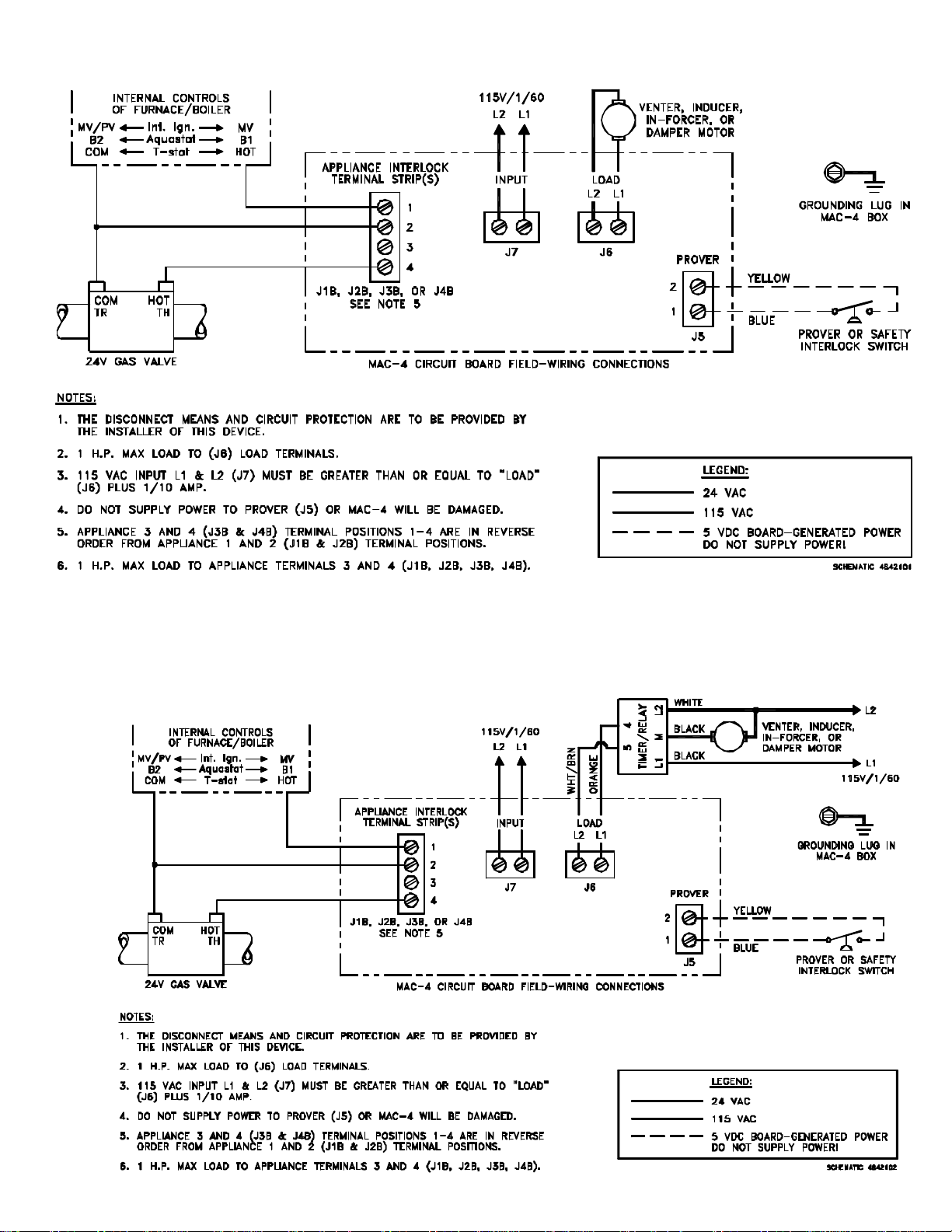
MAC-4 WIRED WITH 24V GAS APPLIANCES AND ONE TJERNLUND POWER VENTER,
DRAFT INDUCER, IN-FORCER OR 115V DAMPER (MOTOR LOAD UP TO 1 H.P.)
2
MAC-4 WIRED WITH 24V GAS APPLIANCES AND ONE TJERNLUND POWER VENTER,
DRAFT INDUCER, IN-FORCER OR 115V DAMPER WITH A 950-1067 POST-PURGE TIMER/RELAY
(VENTER MOTOR LESS THAN 4.4 AMPS)
Page 4

MAC-4 WIRED WITH 24V GAS APPLIANCES AND ONE TJERNLUND POWER VENTER,
DRAFT INDUCER OR IN-FORCER (MOTOR LOAD GREATER THAN 1 H.P.)
MAC-4 WIRED WITH 24V GAS APPLIANCES AND MULTIPLE TJERNLUND POWER VENTERS,
DRAFT INDUCERS OR IN-FORCERS (IF INDIVIDUAL OR COMBINED MOTOR LOAD EXCEEDS 1 H.P.,
SEE DIAGRAM ABOVE FOR EXAMPLE OF ISOLATION RELAY WIRING)
3
Page 5

MAC-4 WIRED WITH 115V GAS APPLIANCES AND ONE TJERNLUND POWER VENTER,
DRAFT INDUCER, IN-FORCER OR 115V DAMPER (MOTOR LOAD UP TO 1 H.P.)
MAC-4 WIRED WITH 115V GAS APPLIANCES AND ONE TJERNLUND POWER VENTER,
DRAFT INDUCER, IN-FORCER OR 115V DAMPER WITH A 950-1067 POST-PURGE TIMER/RELAY
(VENTER MOTOR LESS THAN 4.4 AMPS)
4
Page 6

MAC-4 WIRED WITH 115V GAS APPLIANCES AND ONE TJERNLUND POWER VENTER,
DRAFT INDUCER OR IN-FORCER (MOTOR LOAD GREATER THAN 1 H.P.)
MAC-4 WIRED WITH 115V GAS APPLIANCES AND MULTIPLE TJERNLUND POWER VENTERS,
DRAFT INDUCERS OR IN-FORCERS (IF INDIVIDUAL OR COMBINED MOTOR LOAD EXCEEDS 1 H.P.,
SEE DIAGRAM ABOVE FOR EXAMPLE OF ISOLATION RELAY WIRING)
5
Page 7

MAC-4 WIRED WITH MILLIVOLT GAS APPLIANCES AND ONE TJERNLUND POWER VENTER,
DRAFT INDUCER, IN-FORCER OR 115V DAMPER (MOTOR LOAD UP TO 1 H.P.)
MAC-4 WIRED WITH OIL-FIRED EQUIPMENT AND ONE TJERNLUND POWER VENTER,
DRAFT INDUCER, IN-FORCER OR 115V DAMPER (MOTOR LOAD UP TO 1 H.P.)
6
Page 8

MAC-4 WIRED WITH OIL-FIRED EQUIPMENT AND ONE TJERNLUND POWER VENTER,
DRAFT INDUCER, IN-FORCER OR 115V DAMPER WITH A 950-1067 POST-PURGE
TIMER/RELAY (VENTER MOTOR LESS THAN 4.4 AMPS)
MAC-4 WIRED WITH OIL-FIRED EQUIPMENT AND TJERNLUND SIDESHOT MODEL SS1 OR SS2
WARNING
!
REMOVE FACTORYINSTALLED JUMPER
ON SS1 OR SS2
7
Page 9

MAC-4 WIRED WITH OIL-FIRED EQUIPMENT AND ONE TJERNLUND POWER VENTER,
DRAFT INDUCER OR IN-FORCER (MOTOR LOAD GREATER THAN 1 H.P.)
MAC-4 WIRED WITH OIL-FIRED EQUIPMENT AND MULTIPLE TJERNLUND POWER VENTERS
DRAFT INDUCERS OR IN-FORCERS (IF INDIVIDUAL OR COMBINED MOTOR LOAD EXCEEDS 1 H.P.,
SEE DIAGRAM ON BOTTOM OF PAGE 7 FOR EXAMPLE OF ISOLATION RELAY WIRING)
8
Page 10

SAFETY INTERLOCK TEST
1. Adjust each individual appliance thermostat or aquastat to call for heat.
2. Determine that the Power Venter, Draft Inducer or IN-FORCER operates before the gas valve or burner motor becomes energized.
3. Disconnect main power to MAC-4 board.
4. Remove connection to terminal 2 on Prover terminal block (J5). This will open circuit to the Prover(s) and interrupt the 5 VDC
supplied by the MAC-4 board. Reestablish power to MAC-4 board which was disconnected in Step 3.
5. Adjust each individual appliance thermostat or aquastat to call for heat. The Power Venter, Draft Inducer or IN-FORCER motor
should turn on but the appliance gas valve or burner motor should not be energized with the prover(s) circuit disconnected.
DONOT OPERATE AN APPLIANCE THAT OPERATES WITH THE PROVER CIRCUIT DISCONNECTED!
6. Reconnect the Prover(s) circuit to terminal 2 on Prover terminal block (J5). Repeat steps 1 and 2 above.
Follow Power Venter or Draft Inducer instruction guidelines on combustion air testing.
LIMITED PARTS WARRANTY AND CLAIM PROCEDURE
Tjernlund Products, Inc. warrants the components of its products for one year from date of installation. This warranty covers defects
in material and workmanship. This warranty does not cover normal maintenance, transportation or installation charges for replacement parts or any other service calls or repairs. Products that are tampered with, damaged, or defective due to malfunctioning appliances are not covered under this warranty. This warranty DOES NOT cover the complete MAC-4 if it is operative, except for the
defective part.
Tjernlund Products, Inc. will issue credit or provide a free part to replace one that becomes defective during the one year warranty period. If the part is over 18 months old, proof of date of the installation in the form of the contractor sales/installation receipt is necessary
to prove the unit has been in service for under one year. All receipts should include the date code of the MAC-4 to ensure that the defective component corresponds with the complete unit. This will help preclude possible credit refusal.
1.) If unable to determine faulty component, contact your Tjernlund distributor or Tjernlund Products Technical Customer Service
Department at 1-800-255-4208 for troubleshooting assistance.
2.) After the faulty component is determined, return it to your Tjernlund distributor for replacement. Please include MAC-4 date
code component was taken from. If MAC-4 date code is older than 18 months you will need to provide a copy of the original installation receipt to your distributor. Credit or replacement will only be issued to a Tjernlund distributor after the defective part has been
returned prepaid to Tjernlund.
REPLACEMENT PARTS COVERED BY WARRANTY
MAC-4 Circuit Board only 950-0489
WHAT IS NOT COVERED
Product installed contrary to our installation instructions
Product that has been altered, neglected or misused
Product that has been wired incorrectly
Any freight charges related to the return of the defective part
Any labor charges related to evaluating and replacing the defective part
TJERNLUND LIMITED ONE YEAR WARRANTY
Tjernlund Products, Inc. warrants to the original purchaser of this product that the product will be free from defects due to faulty material or workmanship for a period of (1) year from the date of original purchase or delivery to the original purchaser, whichever is earlier. Remedies under this warranty are limited to repairing or replacing, at our option, any product which shall, within the above stated warranty period, be returned to Tjernlund
Products, Inc. at the address listed below, postage prepaid. THERE ARE NO WARRANTIES WHICH EXTEND BEYOND THE DESCRIPTION ON
THE FACE HEREOF, AND TJERNLUND PRODUCTS, INC. EXPRESSLY DISCLAIMS LIABILITY FOR INCIDENTAL OR CONSEQUENTIAL DAMAGES ARISING FROM THE USE OF THIS PRODUCT. THIS WARRANTY IS IN LIEU OF ALL OTHER EXPRESS WARRANTIES AND NO AGENT
IS AUTHORIZED TO ASSUME FOR US ANY LIABILITY ADDITIONAL TO THOSE SET FORTH IN THIS LIMITED WARRANTY. IMPLIED WARRANTIES ARE LIMITED TO THE STATED DURATION OF THIS LIMITED WARRANTY. Some states do not allow limitation on how long an implied
warranty lasts, so that limitation may may not apply to you. In addition, some states do not allow the exclusion or limitation of incidental or consequential damages, so that above limitation or exclusion may not apply to you. This warranty gives you specific legal rights and you may also have
other rights which may vary from state to state. Send all inquires or products requiring warranty work to Tjernlund Products, Inc. 1601 9th Street, White
Bear Lake, MN 55110-6794. Phone (651) 426-2993 • (800) 255-4208 • Fax (651) 426-9547 • Email us at fanmail@tjfans.com.
9
 Loading...