

Page 1
REV. A 5/99
TJERNLUND PRODUCTS, INC.
1601 Ninth Street • White Bear Lake, MN 55110-6794
PHONE (800) 255-4208 • (651) 426-2993 • FAX (651) 426-9547
Visit our web site • www.tjernlund.com
MODEL
MAC-3
MULTIPLE APPLIANCE CONTROL
For Interlocking one Power Venter, Draft Inducer
IN-FORCERTMor Damper with up to three burners
TABLE OF CONTENTS
Cautions ..........................................................................................................................................................................1
Electrical Wiring
Electrical Specifications & Circuit Board Features .....................................................................................................1
Output Power Venter, Draft Inducer, IN-FORCER & Damper Wiring Diagrams ....................................................2, 3
Burner Input Wiring Diagrams ...............................................................................................................................4, 5
Alternative Wiring Diagrams ..................................................................................................................................5, 6
MAC-3 Wired With up to Five Gas Burners and One Power Venter, Draft Inducer or IN-FORCER................5
MAC-3 Wired With a Power Venter or Draft Inducer and a Commercial IN-FORCER ....................................6
MAC-3 Circuit Board Schematic ....................................................................................................................................6
Replacement Parts & Warranty .......................................................................................................................................7
DESCRIPTION
The MAC-3 is used for wiring up to 3 heating appliances with a single Draft Inducer, Power Venter, IN-FORCER or 115V Damper. It
is suitable for both 24 VAC and 115 VAC control systems for gas and oil burners. Plug-in relays must be purchased separately
depending on control system voltage of appliance.
Use Tjernlund part # 950-1040 relay For 24 VAC control systems.
Use Tjernlund part # 950-0480 relay For 115 VAC control systems.
OWNER INSTRUCTIONS, DO NOT DESTROY
!
Recognize this symbol as an indication of important Safety Information!
THESE INSTRUCTIONS ARE INTENDED AS AN AID TO QUALIFIED, LICENSED
SERVICE PERSONNEL FOR PROPER INSTALLATION, ADJUSTMENT AND
OPERATION OF THIS UNIT. READ THESE INSTRUCTIONS THOROUGHLY
BEFORE ATTEMPTING INSTALLATION OR OPERATION. FAILURE TO FOLLOW
THESE INSTRUCTIONS MAY RESULT IN IMPROPER INSTALLATION, ADJUSTMENT, SERVICE OR MAINTENANCE POSSIBLY RESULTING IN FIRE, ELECTRI CAL SHOCK, CARBON MONOXIDE POISONING, EXPLOSION, OR PERSONAL
INJURY OR PROPERTY DAMAGE.
PLEASE READ CAREFULLY AND KEEP ON JOB
SITE FOR FUTURE REFERENCE.
Copyright © 1999, Tjernlund Products, Inc. All rights reserved. P/N 8504043
Page 2
CAUTIONS
1. Failure to install, maintain and/or operate the MAC-3 in accordance with manufacturer’s instructions may result in conditions that
can produce bodily injury and property damage.
2. The safety interlock and system operation performance checks must be performed on each appliance interlocked with the
MAC-3 in accordance with the Power Venter, Draft Inducer, IN-FORCER or Damper installation instructions.
ELECTRICAL
All wiring from the MAC-3 to the appliance must be appropriate Class 1 wiring as follows: installed in rigid metal conduit, intermediate conduit,
rigid non-metallic conduit, electrical metallic tubing, Type MI Cable, Type MC Cable or be otherwise suitably protected from physical damage.
The disconnect means and circuit protection are to be provided by the installer of this device.
SEQUENCE OF OPERATION OF MAC-3 INTERLOCKED WITH 24 VAC & 115 VAC APPLIANCE CONTROL CIRCUITS
The circuit board of the MAC-3 is designed for a simple three wire interlock with up to three separate burners. Upon a call for heat the “hot”
leg of the burner circuit is intercepted and routed to the MAC-3 terminal strip. The MAC-3 is activated, the power venter, draft inducer,
IN-FORCER or damper starts. The proving switch makes and the intercepted “hot” leg is returned to the burner circuit, allowing the burner to
fire. Plug-in relays must be purchased separately depending on control system voltage of appliance.
Use Tjernlund part # 950-1040 relay For 24 VAC control systems
Use Tjernlund part # 950-0480 relay For 115 VACcontrol systems
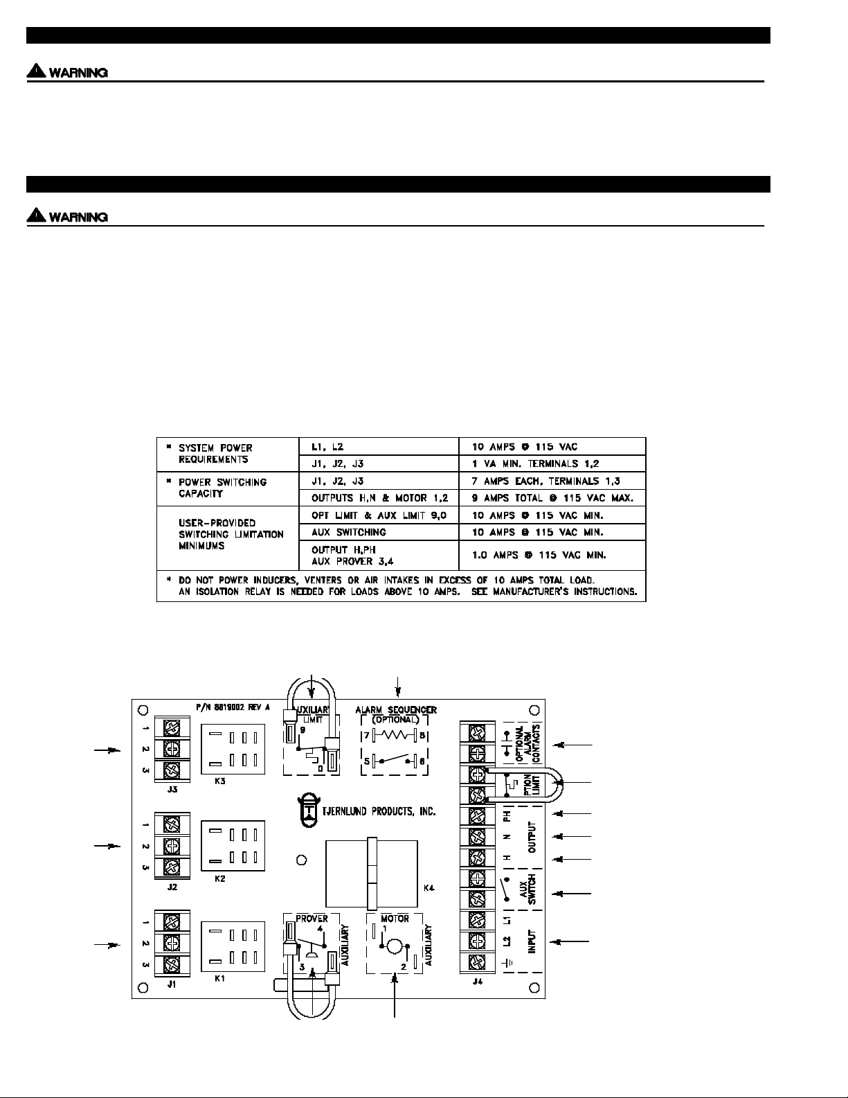
ELECTRICAL SPECIFICATIONS TABLE
Appliance # 3
Interlock
Appliance # 2
Interlock
Appliance # 1
Interlock
MAC-3 CIRCUIT BOARD FEATURES
Aux. Limit switch in series with
optional limit on terminal strip
Optional Alarm Sequencer proves Fan
Prover Operation (not limit operation)
Used in conjunction with Optional Alarm
Sequencer
Optional Limit (Spill Switch)
115 VAC Proven “HOT” From Fan Prover
115 VAC Neutral To Inducer / Venter / IN-FORCER
115 VAC “HOT”To Inducer / Venter
/ IN-FORCER motor & Fan Prover
Auxiliary Operation Switch
(i.e. Manual or Gas Pressure)
115 VAC Input From Disconnect Switch
Aux. Prover contacts in series with H &PH
contacts on output terminals
Aux. Motor in parallel with H &N used for
additional Power Venter, Inducer, IN-FORCER
1
Page 3
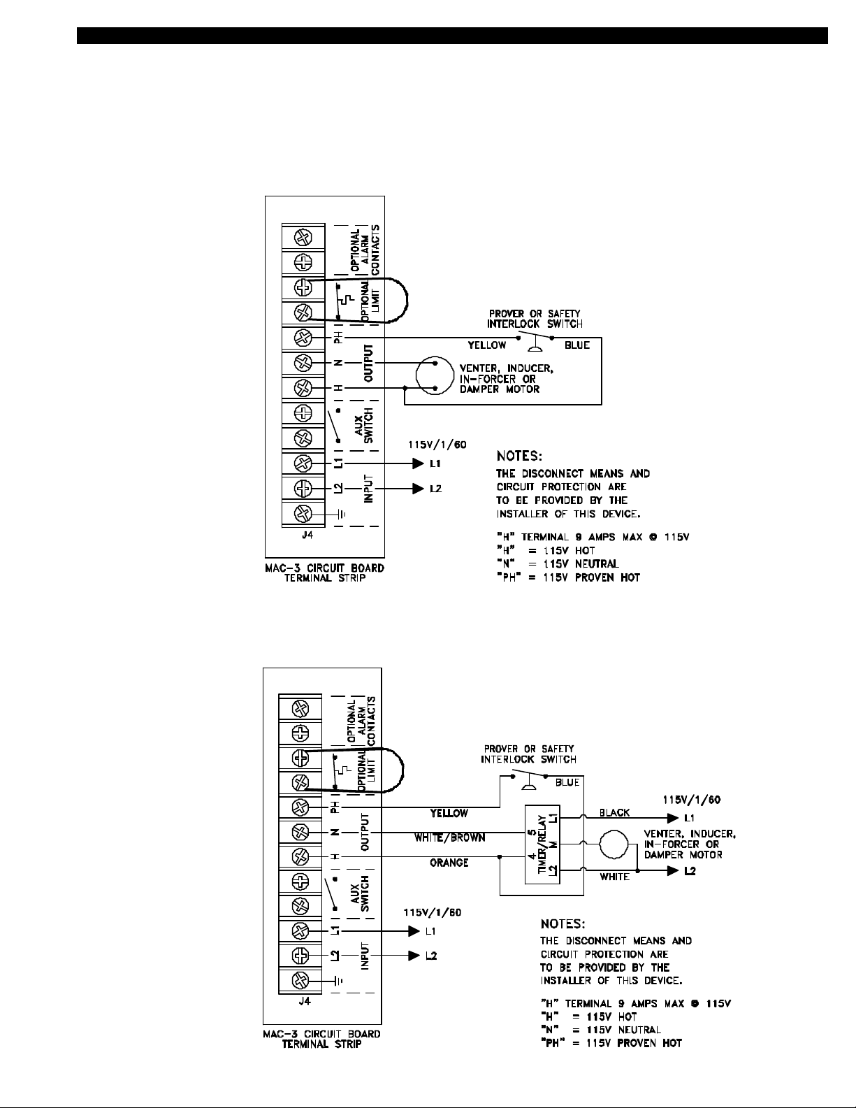
OUTPUT POWER VENTER, DRAFT INDUCER, IN-FORCER & DAMPER WIRING WITH THE MAC-3
2
When wiring the MAC-3 with a Tjernlund Power Venter without a post-purge Timer/Relay only the Fan Proving Switch and motor
leads are utilized for wiring. If you are wiring with a post purge Timer/Relay see wiring on bottom of page 2. Our HSUL Series,
GPAK-J/1 Series and Commercial HS-3,4,5 Series utilize our part # 950-1040 relays which can be plugged into the MAC-3 for 24V
control systems. The HSUL-Series, GPAK-J/1 Series and model HS-5 include one part # 950-1040 relay. The models HS-3 and
HS-4 include two part # 950-1040 relays.
MAC-3 WIRED WITH A TJERNLUND POWER VENTER, DRAFT INDUCER, IN-FORCER OR 115V DAMPER
WITHOUT A POST-PURGE (VENTER MOTOR LESS THAN 9 AMPS)
MAC-3 WIRED WITH A TJERNLUND HST, GPAK-T SERIES POWER VENTER OR DRAFT INDUCER
WITH A 950-1067 POST-PURGE TIMER/RELAY (VENTER MOTOR LESS THAN 4.4 AMPS)
NOTE: The WHITE/BROWN wire from terminal 5 of the Timer/Relay is
ORANGE in the GPAK-T Series. The ORANGE wire from terminal 4 of
the Timer/Relay is BLUE in the GPAK-T Series.
Page 4

MAC-3 WIRED WITH A TJERNLUND MODEL SS1 OR SS2 SIDESHOT® VENT SYSTEM
MAC-3 WIRED WITH A POWER VENTER, DRAFT INDUCER OR IN-FORCER WITH A MOTOR GREATER THAN 9 AMPS
TJERNLUND MODELS INCLUDE THE XL DRAFT INDUCER, HS-5 POWER VENTER & PAI-7 IN-FORCER
3
Page 5

BURNER INPUT WIRING WITH THE MAC-3
The diagrams included with these instructions depict two burners interlocked with the MAC-3 . To wire a third burner to the MAC-3,
purchase the proper control voltage plug-in relay and wire according to the diagram suited for that application.
Use Tjernlund part # 950-1040 relay For 24 VAC control systems
Use Tjernlund part # 950-0480 relay For 115 VAC control systems
MAC-3 WIRED WITH UP TO THREE 24V GAS APPLIANCES
MAC-3 WIRED WITH UP TO THREE 115 VOLT GAS APPLIANCES
4
Page 6

MAC-3 WIRED WITH UP TO THREE OIL BURNERS WITH R8184G CONTROLS - BURNER MOTOR LESS THAN 7 AMPS
MAC-3 WIRED WITH UP TO FIVE 24V GAS BURNERS AND ONE POWER VENTER, DRAFT INDUCER OR IN-FORCER
5
Page 7

MAC-3 WIRED WITH A POWER VENTER OR DRAFT INDUCER AND A COMMERCIAL IN-FORCER
MAC-3 CIRCUIT BOARD WIRING SCHEMATIC
6
Page 8

LIMITED PARTS WARRANTY AND CLAIM PROCEDURE
Tjernlund Products, Inc. warrants the components of its products for one year from date of installation. This warranty covers defects
in material and workmanship. This warranty does not cover normal maintenance, transportation or installation charges for replacement parts or any other service calls or repairs. Products that are tampered with, damaged, or defective due to malfunctioning appliances are not covered under this warranty. This warranty DOES NOT cover the complete MAC-3 if it is operative, except for the
defective part.
Tjernlund Products, Inc. will issue credit or provide a free part to replace one that becomes defective during the one year warranty period. If the part is over 18 months old, proof of date of the installation in the form of the contractor sales/installation receipt is necessary
to prove the unit has been in service for under one year. All receipts should include the date code of the MAC-3 to ensure that the defective component corresponds with the complete unit. This will help preclude possible credit refusal.
1.) If unable to determine faulty component, contact your Tjernlund distributor or Tjernlund Products Technical Customer Service
Department at 1-800-255-4208 for troubleshooting assistance.
2.) After the faulty component is determined, return it to your Tjernlund distributor for replacement. Please include MAC-3 date
code component was taken from. If MAC-3 date code is older than 18 months you will need to provide a copy of the original installation receipt to your distributor. Credit or replacement will only be issued to a Tjernlund distributor after the defective part has been
returned prepaid to Tjernlund.
REPLACEMENT PARTS COVERED BY WARRANTY
24 Volt Relay 950-1040
115 Volt Relay 950-0480
4PDT Isolation Relay 950-0481
Alarm Sequencer 950-0478
Circuit Board only 950-0484
WHAT IS NOT COVERED
Product installed contrary to our installation instructions
Product that has been altered, neglected or misused
Product that has been wired incorrectly
Any freight charges related to the return of the defective part
Any labor charges related to evaluating and replacing the defective part
TJERNLUND LIMITED ONE YEAR WARRANTY
Tjernlund Products, Inc. warrants to the original purchaser of this product that the product will be free from defects due to faulty material or workmanship for a period of (1) year from the date of original purchase or delivery to the original purchaser, whichever is earlier. Remedies under this warranty are limited to repairing or replacing, at our option, any product which shall, within the above stated warranty period, be returned to Tjernlund
Products, Inc. at the address listed below, postage prepaid. THERE ARE NO WARRANTIES WHICH EXTEND BEYOND THE DESCRIPTION ON
THE FACE HEREOF, AND TJERNLUND PRODUCTS, INC. EXPRESSLY DISCLAIMS LIABILITY FOR INCIDENTAL OR CONSEQUENTIAL DAMAGES ARISING FROM THE USE OF THIS PRODUCT. THIS WARRANTY IS IN LIEU OF ALL OTHER EXPRESS WARRANTIES AND NO AGENT
IS AUTHORIZED TO ASSUME FOR US ANY LIABILITY ADDITIONAL TO THOSE SET FORTH IN THIS LIMITED WARRANTY. IMPLIED WARRANTIES ARE LIMITED TO THE STATED DURATION OF THIS LIMITED WARRANTY. Some states do not allow limitation on how long an implied
warranty lasts, so that limitation may may not apply to you. In addition, some states do not allow the exclusion or limitation of incidental or consequential damages, so that above limitation or exclusion may not apply to you. This warranty gives you specific legal rights and you may also have
other rights which may vary from state to state. Send all inquires or products requiring warranty work to Tjernlund Products, Inc. 1601 9th Street, White
Bear Lake, MN 55110-6794. Phone (651) 426-2993 • (800) 255-4208 • Fax (651) 426-9547.
7
 Loading...