

TJERNLUND 950-0486 WHEEL KIT 8504085 REV. 0100, 950-0487 WHEEL KIT 8504085 REV. 0100, 950-1015 WHEEL KIT 8504085 REV. 0100, IN-FORCER, HS-5 User Manual
Page 1
TJERNLUND PRODUCTS, INC.
1601 Ninth Street • White Bear Lake, MN 55110-6794
PHONE (800) 255-4208 • (651) 426-2993 • FAX (651) 426-9547
Visit our web site • www.tjernlund.com
IN-FORCER OR HS-5 WHEEL REPLACEMENT KIT
WARNING: Disconnect power from IN-FORCERTMand equipment before installing new wheel.
OPTION 1 FOR IN-FORCER WHEEL REMOVAL (PREFERRED)
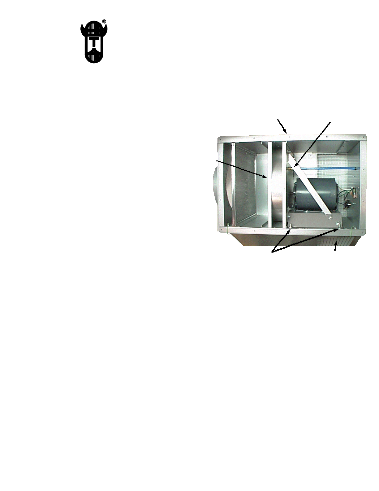
Motor assembly panel
screws (2) in front
Fan prover sensing
tube fitting
1. Remove access door screws on rear of IN-FORCER,
(See Diagram A).
DIAGRAM A
2. Remove screws from wheel housing inlet collar
and remove inlet collar.
Wheel housing
inlet collar
3. Loosen set screw(s) on wheel with allen wrench. If
set screw(s) can not be loosened this way, remove
pipe on discharge side of IN-FORCER if necessary
and loosen set screw(s) through neck of blower housing. Install new wheel making sure it is centered in
blower housing. Tighten set screw(s) on flat of motor
shaft. On model PAI-7 make sure key-way is in wheel
hub. Rotate wheel by hand to make sure it is not
rubbing.
4. Replace inlet collar on housing with tapered end towards
wheel and secure access door.
Blower assembly
bolts (4)
Access door
5. Reconnect power supply. Run IN-FORCER and heating equipment through several heating cycles to verify
proper operation.
OPTION 2 FOR IN-FORCER WHEEL REMOVAL
1. Blower assembly may also be removed from IN-FORCER cabinet if preferred. Remove Access door screws. Remove
(2) motor assembly panel screws on front of IN-FORCER, (See Diagram A).
2. Disconnect motor leads.
3. Remove Fan Prover sensing tube from motor assembly panel by loosening brass compression fitting.
4. Remove (4) bolts which hold blower assembly to IN-FORCER cabinet.
5. Carefully slide out blower assembly from IN-FORCER cabinet.
6. Remove screws from wheel housing inlet collar and remove inlet collar.
7. Loosen set screw(s) on wheel with allen wrench. Install new wheel making sure it is centered in blower housing. Tighten
set screw(s) on flat of motor shaft. On model PAI-7 make sure key-way is in wheel hub. Rotate wheel by hand to make
sure it is not rubbing.
8. Reassemble IN-FORCER following reverse of procedures in steps 6 through 1. Make sure tapered end of inlet collar faces
towards wheel.
9. Reconnect motor leads and power supply. Run IN-FORCER and heating equipment through several heating cycles to
verify proper operation.
For technical assistance contact Tjernlund’s Technical Customer Service at 1-800-255-4208; M-F 7:30 - 4:30 CST.
P/N 8504085 Copyright © 2000 Tjernlund Products, Inc. All rights reserved. REV. 01/00
 Loading...