

Page 1
TJERNLUND PRODUCTS, INC.
1601 Ninth Street • White Bear Lake, MN 55110-6794
PHONE (800) 255-4208 • (651) 426-2993 • FAX (651) 426-9547
Visit our web site • www.tjernlund.com
MODEL HS115-3, HS115-4 & HS115-5 WIRING DIAGRAM ADDENDUM
WARNING:
The BLACK & WHITE Power Venter motor wires shown the diagram below are applicable only for the HS115-3. For models
HS115-4 & HS115-5 use BLACK and WHITE wires from electrical box wip and connect to proper terminals on motor. See motor
nameplate for proper wiring. Upon first startup, as viewed from opposite end of shaft, verify HS115-4 & HS115-5 motors
rotate clockwise. Mount electrical box with Fan Prover in a vertical position. See instructions for proper installation of Fan
Prover Sensing tube. HS115-3,4,5 Motor and Fan Prover specifications are the same as the equivalent HS-3,4,5 model.
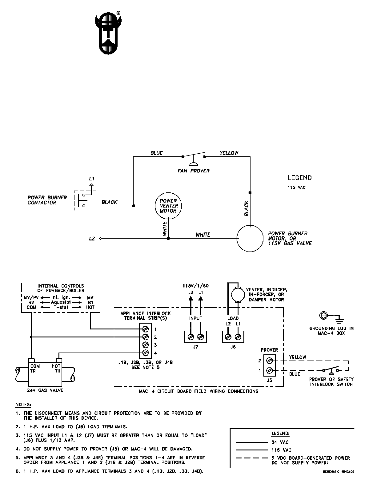
HS115-3, 4, 5 SERIES CONNECTED TO ANY 115V BURNER MOTOR OR GAS VALVE
(BURNER MOTOR OR GAS VALVE LESS THAN 3 AMPS @ 120 VAC)
MAC-4 CONTROL WIRED WITH UP TO FOUR 24V GAS APPLIANCES AND ONE TJERNLUND
HS115-3,4,5 POWER VENTER (MOTOR LOAD UP TO 1 H.P.)
Page 2
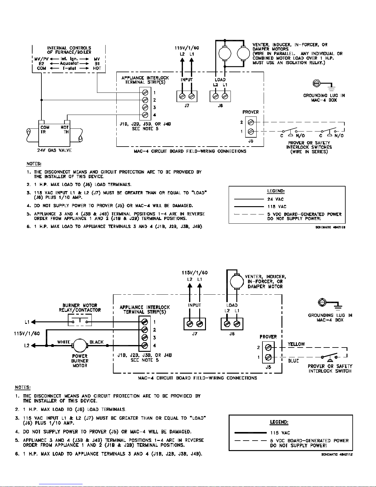
MAC-4 CONTROL WIRED WITH UP TO FOUR 24V GAS APPLIANCES AND MULTIPLE POWER VENTERS &
IN-FORCERS
(IF INDIVIDUAL OR COMBINED MOTOR LOAD EXCEEDS 1 H.P., ISOLATION RELAY(S) WILL HAVE TO BE ADDED)
MAC-4 CONTROL WIRED WITH UP TO FOUR 115V GAS APPLIANCES AND ONE
TJERNLUND HS115-3,4,5 POWER VENTER (MOTOR LOAD UP TO 1 H.P.)
© 2000 Tjernlund Products, Inc. P/N 8505010
Page 3
TJERNLUND PRODUCTS, INC.
1601 Ninth Street • White Bear Lake, MN 55110-6794
PHONE (800) 255-4208 • (651) 426-2993 • FAX (651) 426-9547
Visit our web site • www.tjernlund.com
FOR NATURAL GAS OR LP
REV. A 9/99
MODELS
HS-3
HS-4
HS-5
OWNER INSTRUCTIONS, DO NOT DESTROY
!
Recognize this symbol as an indication of important Safety Information!
NOTE: FLUE GAS TEMPERATURES MUST NOT EXCEED
600oF AT VENT SYSTEM INLET.
THESE INSTRUCTIONS ARE INTENDED AS AN AID TO QUALIFIED, LICENSED
SERVICE PERSONNEL FOR PROPER INSTALLATION, ADJUSTMENT AND
OPERATION OF THIS UNIT. READ THESE INSTRUCTIONS THOROUGHLY
BEFORE ATTEMPTING INSTALLATION OR OPERATION. FAILURE TO FOLLOW
THESE INSTRUCTIONS MAY RESULT IN IMPROPER INSTALLATION, ADJUSTMENT, SERVICE OR MAINTENANCE POSSIBLY RESULTING IN FIRE, ELECTRI CAL SHOCK, CARBON MONOXIDE POISONING, EXPLOSION, PERSONAL
INJURY OR PROPERTY DAMAGE.
DO NOT DESTROY. PLEASE READ CAREFULLY AND KEEP
IN A SAFE PLACE ON JOB SITE FOR FUTURE REFERENCE.
Copyright © 1997, Tjernlund Products, Inc. All rights reserved. P/N 8504031
Page 4
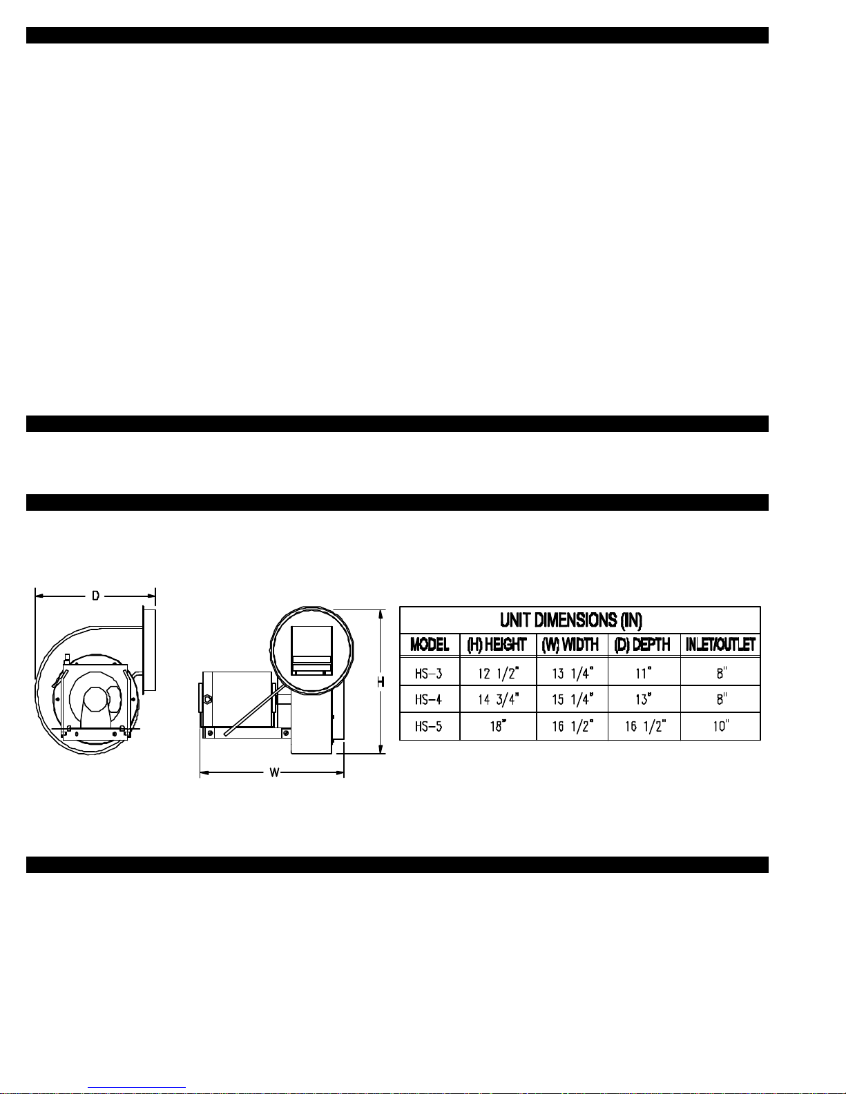
TABLE OF CONTENTS
PAGE(S)
HS-3,4,5 DESCRIPTION ............................................................................................................................................ 1
SPECIFICATIONS ......................................................................................................................................................... 1
HS-3,4,5 SIZING & SELECTION ................................................................................................................................ 1-2
RESTRICTIONS.......................................................................................................................................................... 2-3
INSTALLER CAUTIONS ............................................................................................................................................... 3
VENT HOOD LOCATION ............................................................................................................................................. 3
POWER VENTER MOUNTING .................................................................................................................................... 4
VENT PIPE INSTALLATION ..........................................................................................................................................4
FAN PROVING SWITCH INSTALLATION .................................................................................................................... 5
WIRING .......................................................................................................................................................................5-9
SPECIFICATIONS ........................................................................................................................................... 5
WIRING WITH SINGLE APPLIANCE........................................................................................................... 6-7
WIRING WITH MULTIPLE APPLIANCES & MAC-3 CONTROLLER .......................................................... 8-9
OPERATION SEQUENCE ............................................................................................................................ 10
DRAFT ADJUSTMENT ............................................................................................................................................... 10
SAFETY INTERLOCK ..................................................................................................................................................10
MAINTENANCE .......................................................................................................................................................... 10
HOW TO OBTAIN SERVICE & LIMITED WARRANTY ..........................................................................................10-11
REPLACEMENT PARTS ............................................................................................................................................. 11
Tjernlund Products welcomes your comments and questions. Call us at 800-255-4208, Fax 651-426-9547 or write to:
Customer Service, Tjernlund Products, Inc., 1601 Ninth Street, White Bear Lake, MN 55110-6794.
DESCRIPTION
The Tjernlund Power Venter models HS-3, HS-4 and HS-5 are designed to Side Wall or Vertically vent Natural and LP Gas
appliances. All models are supplied with a Fan Proving Switch which will disable the gas valve if a venting malfunction should occur.
SPECIFICATIONS
SIZING
The installer must verify that the Power Venter is sized properly using the selection table on page 2. The installer may reduce the
vent pipe diameter to the size shown in the selection table immediately after the draft hood, draft diverter or barometric draft control.
The vent pipe length shown includes all vent pipe before and after the Power Venter. To calculate the equivalent vent pipe length,
add the straight vent pipe plus 10 feet for every 90 degree elbow and 5 feet for every 45 degree elbow.
If venting multiple appliances with one Power Venter, the total combined BTU/hr. input of all appliances must be added together to
size the Power Venter.
IMPORTANT: Elbows placed directly after discharge on Power Venter may cause erratic operation of Fan Prover. If elbows are
necessary on discharge, allow for a straight section of pipe 3 times the vent diameter being used before installing an elbow.
1
Page 5
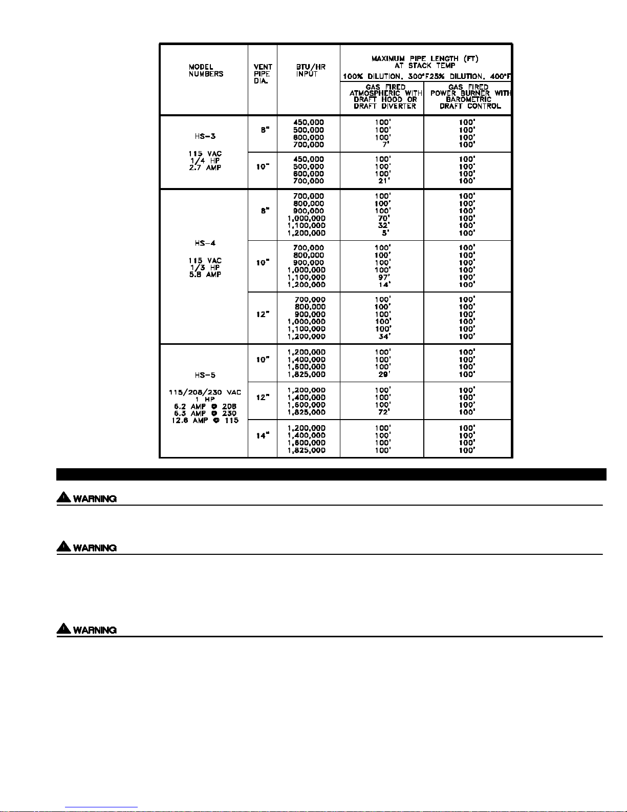
MODEL
SELECTION
TABLE
Failure to install, maintain and/or operate the Power Venter in accordance with manufacturer's instructions may result in conditions
which can produce bodily injury and property damage.
The Power Venter must be installed by a qualified installer in accordance with these instructions and all local codes or in their
absence in accordance with the latest edition of The National Fuel Gas Code (NFPA #54), The latest edition of the National Electrical
Code (NFPA#70) and the Occupational Safety and Health Act (OSHA) when applicable. Improper installation can create a hazardous
condition such as an explosion, fire, electrical shock or carbon monoxide poisoning resulting in property damage, personal injury or
death.
Disconnect the power supply when making wiring connections or when working around the fan wheel and motor. Failure to do so can
result in electrical shock, personal injury, death or property damage.
1. The Power Venter may only be installed on Natural Gas or LP Gas appliances.
2. The Power Venter may not be installed on incinerators, incinerating toilets, condensing-type appliances or solid-fuel burning
appliances.
3. The Power Venter shall not be installed on an appliance with an automatic valve having a manual opener unless the manual
opener has been rendered inoperative or the automatic valve has been replaced with a valve not equipped with a manual opener.
4. The Power Venter may only be installed on appliance equipped with a draft hood, draft diverter or barometric draft control.
INSTALLATION RESTRICTIONS
2
Page 6

5. The Power Venter shall not be installed where the flue gas temperature exceeds 600oF. at the Power Venter inlet. Flue gas
temperature verification:
A) Consult appliance manufacturer for flue gas temperature after dilution by the draft hood, draft diverter or barometric draft control.
B) Measure flue gas temperature at the Power Venter inlet after installation. Temperature should be measured after appliance and
Power Venter have operated for at least 15 minutes, allowing the flue gas temperature to stabilize.
6. The Power Venter must be mounted so that the shaft of the motor remains horizontal to prevent motor bearing wear.
7. Power Venter electrical box must be mounted with the Fan Proving Switch in a vertical position.
8. Ambient temperature surrounding Power Venter must not exceed 104o F.
4
F444444
444444444444444 CAUTIONS
INSTALLER CAUTIONS
1. Plan the vent system so that the code required clearances are maintained from plumbing and wiring.
2. To prevent personal injury and equipment damage, disconnect power supply when working on Power Venter.
3. Make certain the power supply is adequate for Power Venter motor requirements. Do not add the Power Venter to a circuit where
the total load is unknown.
4. The installer must verify that the appliance on which the Power Venter will be installed is in a safe operating condition. Consult
appliance manufacturer’s Instructions for details.
5. Plan the vent system layout so that the Power Venter is as close to the point of termination as possible. Vent pipe between the
Power Venter and Vent Hood is acceptable. However, all vent pipe connections after the Power Venter discharge will be under positive pressure during operation and must be sealed with high-temperature caulk or aluminum vent pipe tape to prevent flue gas leakage into the structure.
VENT HOOD LOCATION
This section only applies if using a Power Venter to Sidewall vent. If using Power Venter to exhaust the flue gases vertically, skip to
the section titled “POWER VENTER MOUNTING” on page 4.
If possible, locate the Vent Hood on a wall that does not face the direction of prevailing winds. This will diminish the possibility of
appliance interruption during periods of extreme winds.
If possible, locate the Vent Hood no closer than 3 feet from an inside corner of an L-shaped structure.
CODE REQUIREMENTS
Terminate the vent system so that proper minimum clearances are maintained as cited in the latest edition of the National Fuel Gas
Code (NFPA # 54) and the latest edition of Chimneys, Fireplaces, Vents, and Solid Fuel Burning Appliances, (NFPA #211), or as follows:
• Not be less than 7 feet above grade when located adjacent to public walk ways.
• At least 3 feet above any forced air inlet located within 10 feet.
• At least 4 feet below, 4 feet horizontally from or 1 foot above any door, window or gravity air inlet into any building.
• At least 1 foot above grade.
• So that the flue gases are not directed so as to jeopardize people, overheat combustible structures or enter buildings, and
• Not less than 2 feet from an adjacent building.
Page 7

POWER VENTER MOUNTING
The installer must supply plumber’s strap or 1/4” threaded rod with nuts and washers for mounting. The Power Venter may be mounted in any position as long as the shaft of the motor remains horizontal. The Power Venter housing is single wall, 6 inches must be
maintained from all combustible materials. It is recommended that the Power Venter be mounted as close as possible to the point of
termination.
HS-3 HS-4, HS-5
VENT PIPE INSTALLATION
If Installing the Power Venter on an appliance not equipped with a draft hood or draft diverter (e.g. Power Burners, Induced Draft), a
barometric draft control must be added. The barometric draft control must be the same size as the flue outlet and installed as close
as possible to the appliance. After the draft hood, draft diverter or barometric draft control, a tapered reducer should be installed to
reduce the flue to the size shown in the selection table on page 2 of these instructions. After the tapered reducer, install the appropriate type of vent pipe to the inlet of the Power Venter. The vent pipe chosen must be in compliance with local codes. The Power
Venter inlet and outlet are designed to accept single wall vent pipe. If using vent pipe other than single wall, the installer must supply
adapters to connect to the Power Venter. While it is recommended that the Power Venter be mounted at the point of termination, it is
acceptable to install vent pipe between the outlet of the Power Venter and the point of termination. The Installer must seal all vent
pipe connections after the Power Venter with high-temperature caulk or aluminum vent pipe tape to prevent flue gas leakage during
operation. The size of the vent pipe between the Power Venter and point of termination should be the same size shown on the selection table. Support the vent pipe as recommended by it’s manufacturer. Examples of proper vent pipe installation are shown below.
IMPORTANT: Elbows placed directly after discharge on Power Venter may cause erratic operation of Fan Prover. If elbows are
necessary on discharge, allow for a straight section of pipe 3 times the vent diameter being used before installing an elbow.
4
Page 8

FAN PROVINGSWITCH INSTALLATION
As viewed from the opposite end of the shaft, the motor should rotate clockwise.
NOTE: It is important that the electrical box is mounted with the
1. Mount supplied electrical box to a flat surface within 2 feet of
2. Connect the 1/4” aluminum tubing from the Fan Proving
All wiring from the Power Venter to the appliance must be in compliance with the local codes or in their absence, the National Electric
Code (NFPA #70).
All wiring from the Power Venter to the appliance must be appropriate class 1 wiring as follows: Installed in rigid metal conduit, inter mediate metal conduit, rigid non-metallic conduit, electrical metallic tubing, Type MI Cable or be otherwise suitably protected from
physical damage.
Fan Proving Switch in a vertical position.
the Power Venter with Proving Switch in a vertical position.
Switch to the Power Venter housing using supplied fittings.
The factory calibrated sensing tube length and compression
fittings are critical for proper operation of the Fan Proving
Switch. If it is necessary to alter the sensing tube length,
ONLY trim sensing tube portion that is on the exterior of the
housing. DO NOT trim the sensing tube portion that will be
mounted in the interior of the housing. No attempts should
be made to substitute the specified materials. See Fan
Proving Switch installation diagram.
ELECTRICAL SPECIFICATIONS
NOTE:
WIRING
5
Page 9

MODEL HS-3, HS-4, HS-5 WIRING WITH SINGLE APPLIANCE
The HS-3, HS-4, and HS-5 Power Venters are equipped with 2 relays. One is used to activate the Power Venter while the other is
used to isolate the Fan Proving Switch from the load of the appliance. The relays and Fan Proving Switch are factory wired for easy
installation. The installer needs to complete 3 steps to wire the Power Venter as noted below:
1. Route the metal conduit from the electrical box to the Power Venter motor and connect the Black, White and Ground wires to the
motor.
2. Connect the Red, Blue and Orange wires in the electrical box to the appliance.
3. Supply 115 VAC to the input wires in the electrical box.
NOTE: All models as viewed from the opposite end of the shaft should rotate clockwise. The motor should be wired correctly by
Tjernlund for proper rotation.
INTERNAL WIRING OF H
FACTORY WIRING OF HS-3, HS-4, HS-5 ELECTRICAL BOX
LADDER DIAGRAM OF HS-3, HS-4, HS-5
6
Page 10

MODELS HS-3, HS-4, HS-5 CONNECTION DIAGRAMS WITH SINGLE APPLIANCE
The diagrams below represent common ways in which the HS-3, HS-4, HS-5 Power Venters are interlocked to 24V controlled appliances. Variations of these diagrams are acceptable as long as the Fan Proving Switch isolation circuit is wired to disable the gas
valve if a venting malfunction should occur.
HS-3, HS-4, HS-5 CONNECTED TO APPLIANCE WITH SPARK IGNITION
WARNING:
The BLACK & WHITE motor
wires shown in this diagram are
applicable only for the HS-3.
For models HS-4 & HS-5 use
BLACK and WHITE wires from
electrical box wip and connect to
proper terminals on motor. See
motor nameplate for proper
wiring.
WARNING:
The BLACK & WHITE motor
wires shown in this diagram are
applicable only for the HS-3.
For models HS-4 & HS-5 use
BLACK and WHITE wires from
electrical box wip and connect to
proper terminals on motor. See
motor nameplate for proper
wiring.
HS-3, HS-4, HS-5 CONNECTED TO A BOILER
7
Page 11

MODELS HS-3, HS-4, HS-5 CONNECTED WITH UP TO 3 24V GAS APPLIANCES WITH MAC-3 PART # 950-0460
NOTE:
The MAC-3 Multiple Appliance Controller Part
# 950-0460 is a used for wiring up to 3 heating
appliances with a single Power Venter. Plug-in
relays must be purchased separately depending
on control system voltage of appliance. This diagram depicts interlock with 24V controlled gas
equipment.
Use Tjernlund part # 950-1040 relay For 24 VAC
control systems.
The HS-3,4,5 Series utilize our part # 950-1040
24V relays which can be plugged into the MAC-3
for 24V control systems. The models HS-3 and
HS-4 include two part # 950-1040 relays. The
model HS-5 includes one part # 950-1040 relay.
For HS-3 & HS-4 Power Venter output wiring to
MAC-3, see top of page 9. For HS-5 Power
Venter output wiring to MAC-3, see bottom of
page 9.
MODELS HS-3, HS-4, HS-5 CONNECTED WITH UP TO 3 115V GAS APPLIANCES WITH MAC-3 PART # 950-0460
NOTE:
The MAC-3 Multiple Appliance Controller Part # 950-0460 is a used for wiring up to 3 heating appliances with a single Power Venter.
Plug-in relays must be purchased separately depending on control system voltage of appliance. This diagram depicts interlock with
115V controlled gas equipment.
Use Tjernlund part # 950-0480 relay For 115 VAC control systems.
For HS-3 & HS-4 Power Venter output wiring to MAC-3, see top of page 9. For HS-5 Power Venter output wiring to MAC-3, see
bottom of page 9.
8
Page 12

MAC-3 PART # 950-0460 OUTPUT WIRING WITH A POWER VENTER
When wiring the MAC-3 with a Tjernlund HS-3, HS-4 or HS-5 Power Venter only the Fan Proving Switch and motor leads are utilized
for wiring. The HS-3,4,5 Series utilize our part # 950-1040 relays which can be plugged into the MAC-3 for 24V control systems. The
model HS-3 and HS-4 include two part # 950-1040 relays. The model HS-5 includes one part # 950-1040 relay.
MODELS HS-3 & HS-4 POWER VENTER OUTPUT WIRING TO MAC-3
(POWER VENTER MOTOR LESS THAN 9 AMPS)
NOTE:
For appliance interlock with MAC-3 and
24V controlled appliances, see diagram on
top of page 8.
For appliance interlock with MAC-3 and
115V controlled appliances, see diagram on
bottom of page 8.
MODEL HS-5 POWER VENTER OUTPUT WIRING TO MAC-3
(POWER VENTER MOTOR GREATER THAN 9 AMPS)
115/115V RELAY
TJERNLUND PART # 950-0483
NOTE:
For appliance interlock with MAC-3
and 24V controlled appliances, see
diagram on top of page 8.
For appliance interlock with MAC-3
and 115V controlled appliances,
see diagram on bottom of page 8.
9
Page 13

SEQUENCE OF OPERATION FOR POWER VENTER ON A SINGLE APPLIANCE
The following sequence of operation gives guidance as to how the Power Venter should operate with the appliance.
1. The call for heat will be routed through the Motor Relay and to one side of the Fan Proving Switch. The Power Venter motor is
energized.
2. When the Power Venter has achieved full RPM and Maximum draft has been established, the Fan Proving Switch will close
allowing the 24V signal to energize the Isolation Relay coil.
3. When the Isolation Relay contacts close, the 24V signal will then be allowed to reach the gas valve.
DRAFT ADJUSTMENT
DRAFT ADJUSTMENT FOR GAS APPLIANCES EQUIPPED W ITH A DRAFT HOOD OR DRAFT DIVERTER
1. With the appliance(s) and Power Venter operating for at least 15 minutes, hold a taper, cigarette or other smoke producing device
at the draft hood or draft diverter.
2. Determine that the smoke is being drawn into the vent system.
3. If the draft appears to be excessive, the damper on the Power Venter may be adjusted to reduce the Power Venter’s performance
as long as the smoke is still being drawn into the draft hood after damper adjustment.
DRAFT ADJUSTMENT FOR GAS APPLIANCES EQUIPPED WITH A BAROMETRIC DRAFT CONTROL
1. With the appliance(s) and Power Venter operating for at least 15 minutes, insert a draft gauge into the vent pipe between the
barometric draft control and the appliance flue outlet.
2. Make necessary draft adjustments with the barometric draft control, appliance burner air intake and the damper located on the
outlet of the Power Venter until the appliance manufacturer’s recommended draft is present.
SAFETY INTERLOCK TEST
1. Adjust the appliance thermostat(s) or aquastat(s) to call for heat.
2. Determine that the Power Venter operates before the gas valve becomes energized.
3. With the appliance(s) and Power Venter operating, disrupt power to the Power Venter and determine that the appliance gas valve
shuts off.
DONOT OPERATE AN APPLIANCE THAT DOES NOTSHUTOFF WITH THE VENTER DISABLED.
MAINTENANCE
1. Oil every six months with 2 drops of S.A.E. #20. The oil ports are located at both ends of the motor.
2. A vent pipe inspection must be performed annually. The inspection should include checking all vent pipe and connections for
blockage and leaks. A safety interlock test should also be performed.
HOW TO OBTAIN SERVICE ASSISTANCE
1. If you have any questions about your Power Venter or if it requires adjustment, repair or routine maintenance, we suggest that
you contact your installer, contractor or service agency.
2. If you require technical information contact Tjernlund Products, Inc. at 1-800-255-4208.
When contacting Tjernlund Products, Inc., please have the following information available:
1. Model number of the Power Venter
2. Name and address of installer and service agency
3. Date of original installation and dates any service work was performed
4. Details of the problem
10
Page 14

LIMITED PARTS WARRANTY AND CLAIM PROCEDURE
Tjernlund Products, Inc. warrants the components of its products for one year from date of installation. This warranty covers defects
in material and workmanship. This warranty does not cover normal maintenance, transportation or installation charges for replacement parts or any other service calls or repairs. Products that are tampered with, damaged, or defective due to malfunctioning appliances are not covered under this warranty. This warranty DOES NOT cover the complete Power Venter if it is operative, except for
the defective part.
Tjernlund Products, Inc. will issue credit to the original distributor or provide a free part to replace one that becomes defective during the
one year warranty period. If the part is over 18 months old, proof of date of the installation in the form of the contractor sales/installation receipt is necessary to prove the unit has been in service for under one year. All receipts should include the date code of the Power
Venter to ensure that the defective component corresponds with the complete unit. This will help preclude possible credit refusal.
1.) Determine defective component. If unable to determine faulty component, contact your Tjernlund distributor or Tjernlund Products
Technical Customer Service Department at 1-800-255-4208 for troubleshooting assistance.
2.) After the faulty component is determined, return it to your Tjernlund distributor for replacement. Please include Power Venter date
code component was taken from. The date code is located on the Electrical Box cover plate. If Power Venter date code is older
than 18 months you will need to provide a copy of the original installation receipt to your distributor. Credit or replacement will only
be issued to a Tjernlund distributor after the defective part has been returned prepaid to Tjernlund.
COVERED PARTS
Motor Proving Switch Relays Wheel Housing
WHAT IS NOT COVERED
Product installed contrary to our installation instructions
Product that has been altered, neglected or misused
Product that has been wired incorrectly
Product that has been damaged by a malfunctioning or mistuned burner
Any freight charges related to the return of the defective part
Any labor charges related to evaluating and replacing the defective part
TJERNLUND LIMITED ONE YEAR WARRANTY
Tjernlund Products, Inc. warrants to the original purchaser of this product that the product will be free from defects due to faulty material or workmanship for a period of (1) year from the date of original purchase or delivery to the original purchaser, whichever is earlier. Remedies under this warranty are limited to repairing
or replacing, at our option, any product which shall, within the above stated warranty period, be returned to Tjernlund Products, Inc. at the address listed below,
postage prepaid. THERE ARE NO WARRANTIES WHICH EXTEND BEYOND THE DESCRIPTION ON THE FACE HEREOF, AND TJERNLUND PRODUCTS,
INC. EXPRESSLY DISCLAIMS LIABILITY FOR INCIDENTAL OR CONSEQUENTIAL DAMAGES ARISING FROM THE USE OF THIS PRODUCT. THIS WARRANTY IS IN LIEU OF ALL OTHER EXPRESS WARRANTIES AND NO AGENT IS AUTHORIZED TO ASSUME FOR US ANY LIABILITY ADDITIONAL TO
THOSE SET FORTH IN THIS LIMITED WARRANTY. IMPLIED WARRANTIES ARE LIMITED TO THE STATED DURATION OF THIS LIMITED WARRANTY.
Some states do not allow limitation on how long an implied warranty lasts, so that limitation may not apply to you. In addition, some states do not allow the exclusion or limitation of incidental or consequential damages, so that above limitation or exclusion may not apply to you. This warranty gives you specific legal rights
and you may also have other rights which may vary from State to State. Send all inquiries regarding warranty work to Tjernlund Products, Inc. 1601 9th Street,
White Bear Lake, MN 55110-6794. Phone (651) 426-2993 • (800) 255-4208 • Fax (651) 426-9547.
REPLACEMENT PARTS
MODEL HS-3
MOTOR KIT 950-1022
WHEEL KIT 950-1013
FAN PROVER KIT 950-1032
HOUSING 950-1014
ISOLATION OR 950-1040
MOTOR RELAY
MODEL HS-4
MOTOR KIT* 950-0131
WHEEL KIT 950-1013
FAN PROVER KIT 950-1007
HOUSING 950-1008
ISOLATION OR 950-1040
MOTOR RELAY
MODEL HS-5
MOTOR KIT 950-1017
WHEEL KIT 950-1015
FAN PROVER KIT 950-1007
HOUSING 950-1018
MOTOR RELAY KIT 950-1016
ISOLATION RELAY 950-1040
*May need shaft extension kit if old
shaft extension can not be removed
from defective motor.
11
 Loading...