

Page 1
DESCRIPTION
Tjernlund's Hot Shot™ Universal Stove Blower Heat Shield allows for the proper installation of the fan on stoves which do
not have an existing heat shield.
INSTALLATION
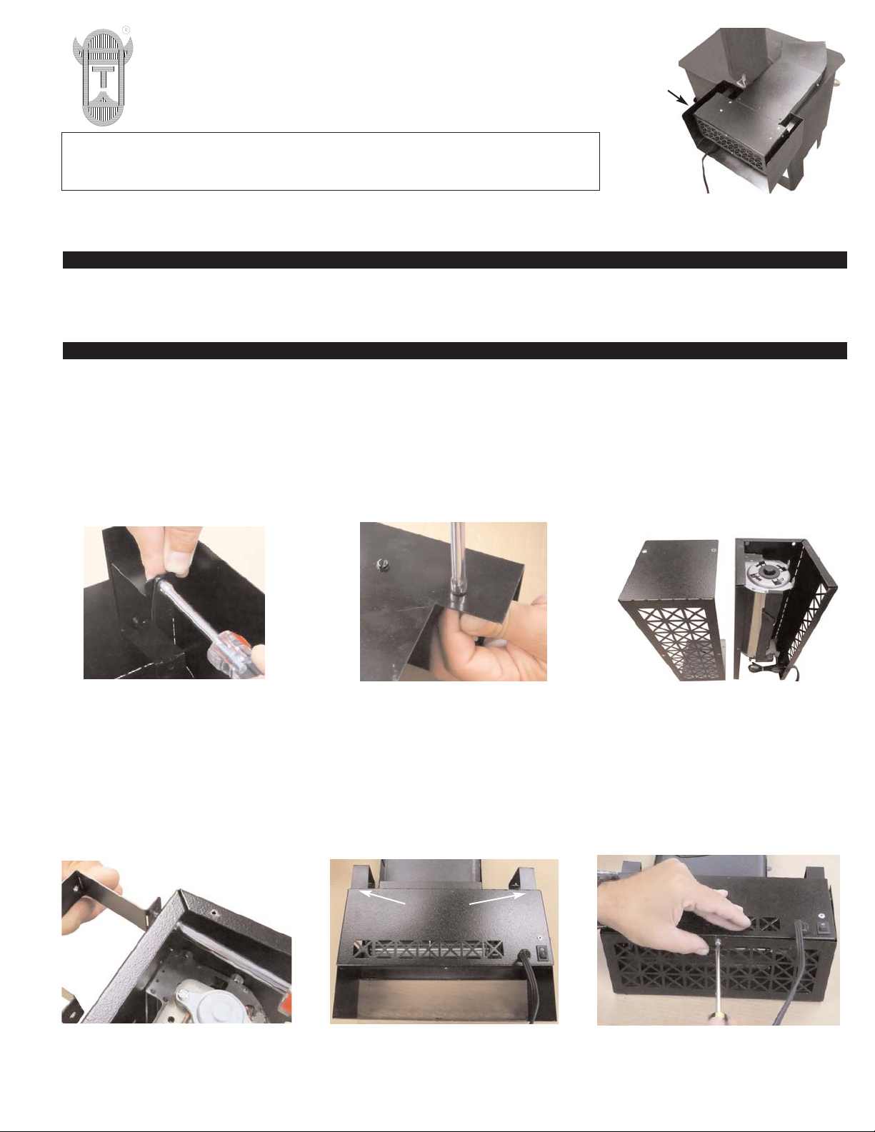
ATTACHING HEAT SHIELD TO BLOWER HOUSING
1. Unscrew and remove Stove Top Edge Clip from the heat shield bracket, (See Figure A). Save for later use in Step 7.
2. Unscrew the (2) brackets from the inside of the heat shield, (See Figure B).
3. Separate the SB1 main blower housing and the back cover by removing the (6) screws that attach them, (See Figure C).
4. Attach the (2) brackets removed from the heat shield in Step 2 to the outside front of the main blower housing. Insert
screws through housing from inside the SB1 main blower housing and screw into the (2) feet of each bracket, (See
Figures D and E).
5. Reattach the back cover to the SB1 main blower housing with (6) screws removed in Step 3, (See Figures E and F).
Hot Shot™ Universal Stove Blower Heat Shield, P/N (950-9200)
©2011 TJERNLUND PRODUCTS, INC. ALL RIGHTS RESERVED P/N: 8504184
TJERNLUND PRODUCTS, INC.
1601 Ninth Street • White Bear Lake, MN 55110-6794
PHONE (800) 255-4208 • (651) 426-2993 • FAX (651) 426-9547
Visit our web site • www.tjernlund.com
READ OWNERS INSTRUCTIONS CAREFULLY PRIOR TO INSTALLATION.
THESE INSTRUCTIONS MUST REMAIN WITH EQUIPMENT. DO NOT DESTROY.
FIGURE A
FIGURE B FIGURE C
FIGURE D
HEAT
SHIELD
FIGURE E FIGURE F
BRACKETS
ATTACHED
Page 2
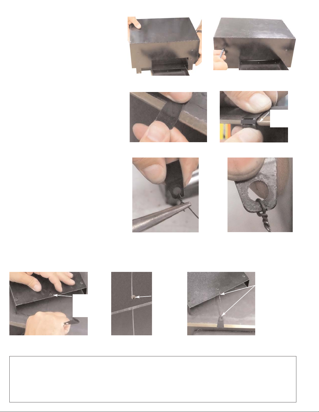
6. Attach heat shield to SB1 main blower housing.
Align holes of heat shield with those of the top
of the brackets that were attached to the SB1
blower housing in Step 4. Use (4) of the included screws to attach heat shield to brackets,
(See Figures G and H).
MOUNTING HEAT SHIELD / BLOWER
ASSEMBLY TO STOVE TOP
7. Use light pressure to form Stove Top Edge Clip
into a hooked shape that will grab the front edge
of the stove top. Forming bend will be easiest
along areas where material has been removed.
Do not bend repeatedly as this may wear material and cause it to weaken or break, (See Figures
I and J).
8. Feed included wire through hole on Stove Top
Edge Clip and twist wire with pliers to create a
permanent attachment. Leave wire on one end
for attachment to heat capture chute of blower
assembly and clip excess wire on other end to
remove poking hazard, (See Figures K and L).
9. Feed wire through center hole of directional
heat capture chute extension until Stove Top
Edge Clip is tight against the stove top front edge
and wire is taut, (See Figure M). NOTE: If directional chute extension is not used, use hole in
center of heat capture chute.
10. Wrap excess wire around hole, twist to provide a permanent hold and clip excess wire (See Figures N and O).
WARRANT
TJERNLUND LIMITED ONE YEAR WARRANTY
Tjernlund Products, Inc. warrants to the original purchaser of this product that the product will be free from defects due to faulty material or workmanship for a period of (1) year from the date of original
purchase or delivery to the original purchaser, whichever is earlier. Remedies under this warranty are limited to repairing or replacing, at our option, any product which shall, within the above stated warranty period, be returned to Tjernlund Products, Inc. at the address listed below, postage prepaid. THERE ARE NO WARRANTIES WHICH EXTEND BEYOND THE DESCRIPTION ON THE FACE
HEREOF, AND TJERNLUND PRODUCTS, INC. EXPRESSLY DISCLAIMS LIABILITY FOR INCIDENTAL OR CONSEQUENTIAL DAMAGES ARISING FROM THE USE OF THIS PRODUCT. THIS
WARRANTY IS IN LIEU OF ALL OTHER EXPRESS WARRANTIES AND NO AGENT IS AUTHORIZED TO ASSUME FOR US ANY LIABILITY ADDITIONAL TO THOSE SET FORTH IN THIS LIMITED
WARRANTY. IMPLIED WARRANTIES ARE LIMITED TO THE STATED DURATION OF THIS LIMITED WARRANTY. Some states do not allow limitation on how long an implied warranty lasts, so that
limitation may not apply to you. In addition, some states do not allow the exclusion or limitation of incidental or consequential damages, so that above limitation or exclusion may not apply to you. This
warranty gives you specific legal rights and you may also have other rights which may vary from State to State. Send all inquiries regarding warranty work to Tjernlund Products, Inc. 1601 9th Street,
White Bear Lake, MN 55110-6794. Phone (651) 426-2993 • (800) 255-4208 • Fax (651) 426-9547 • Email fanmail@tjfans.com.
FIGURE G
FIGURE J
FIGURE K
FIGURE L
FIGURE I
FIGURE M FIGURE OFIGURE N
FIGURE H
CONNECT STOVE
TOP EDGE CLIP TO
FRONT OF STOVE
AND WIRE TO CENTER HOLE IN HEAT
CAPTURE OR DIRECTIONAL CHUTE.
IMPORTANT: WIRE
MUST BE TAUT.
FORM STOVE
CLIP AROUND
STOVE TOP
EDGE
FEED WIRE
FROM STOVE
CLIP THROUGH
HEAT CAPTURE
CHUTE HOLE
WIRE FROM
STOVE CLIP
FED THROUGH
HEAT CAPTURE
CHUTE HOLE
 Loading...