

Page 1
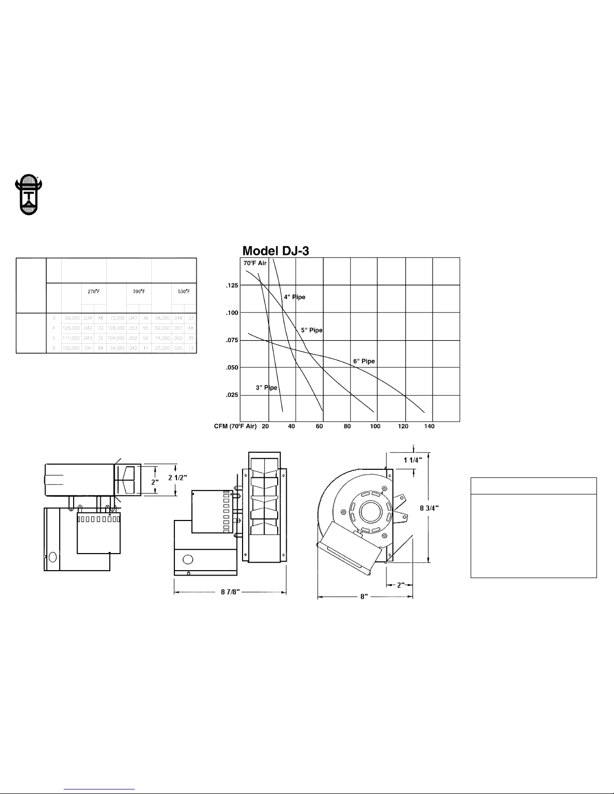
MODEL DJ-3 DRAFT INDUCER
SPECIFICATIONS
Performance Curves
MOTOR SPECIFICATIONS
ELECTRICAL DATA
Volts 115
Hertz 60
RPM 1550
Watts 35
Amps .43
Therm. Prot. Imp. Prot.
P/N 8506000
REV. C 11/05
INPUT
HEATER
CONTROL
BAR. DRAFT
GAS FIRING
NO.
MODEL
DJ-3
INPUT
BTU
HEATER
DRAFT HOOD
GAS FIRING
SIZE
IN.
PIPE
FLUE GAS
S.P. CFM
WITH
BTU
OIL FIRING
HEATER
CONTROL
BAR. DRAFT
FLUE GAS
INPUT
CFMS.P.
WITH
BTU
FLUE GAS
CFMS.P.
WITH
TJERNLUND PRODUCTS, INC.
1601 Ninth Street • White Bear Lake, MN 55110-6794
PHONE (800) 255-4208 • (651) 426-2993 • FAX (651) 426-9547
Visit our web site • www.tjernlund.com
1. Inputs shown are believed to be
maximum capacities for inducers when
mounted on pipe sizes shown for
ordinary jobs where a moderate amount
of mechanical induced draft is required.
2. Consideration is given to typically
higher static pressure requirements for
larger installations, for the type of fuel
burned and for the type of draft control
installed.
3. Where pressure requirements are
unknown or believed to be unusually
severe, ask for complete performance
curves or consult factory.
4. All ratings have been developed in our
testing and research department and
have been approved by a nationally
known independent testing laboratory.
Certification is available upon request.
5. Heating capacities shown are for 1000
BTU per cubic foot natural gas and for
139,000 BTU per gallon No. 2 fuel oil.
Consult factory for capacities with other
fuels. Heating capacities are based on
typical combustion efficiencies and
allow for approximately 5 percent
ambient air drawn into inducer to
cool motor and drives.
6. Draft Inducers should be installed
in single wall vent pipe in order
to insure proper performance.
Note: Tjernlund Products, Inc. reserves the
right to make changes to specifications without
notification.
Static pressure inches H20 (70
o
F Air)
Static pressures shown are “negative” and apply only on inlet side
Page 2
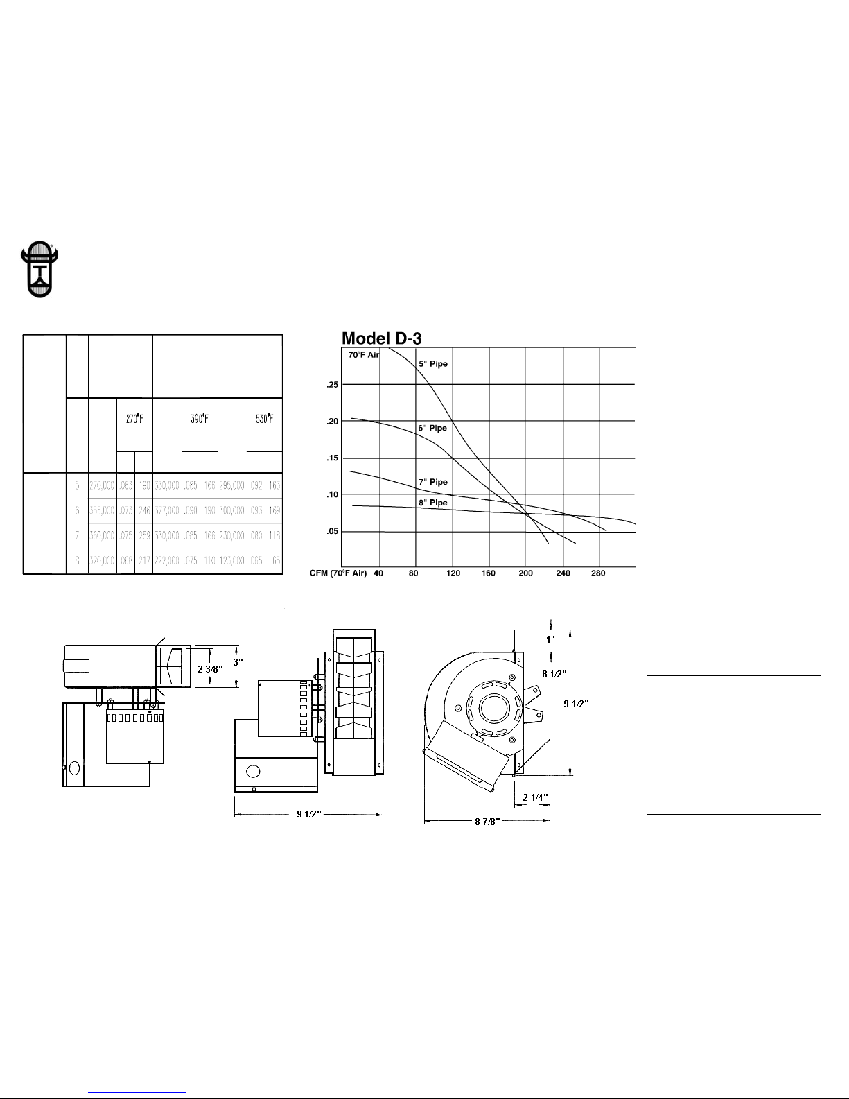
MODEL D-3 DRAFT INDUCER
SPECIFICATIONS
Performance curves
D-3
MODEL
NO.
WITHWITH
GAS FIRING
PIPE
CONTROL
BAR. DRAFT
DRAFT HOOD
WITH
IN.
SIZE
CONTROL
BAR. DRAFT
GAS FIRING OIL FIRING
FLUE GASFLUE GAS
INPUT
HEATER
BTU
HEATER
INPUT
BTU
FLUE GAS
INPUT
BTU
HEATER
S.P. CFM S.P. CFM S.P. CFM
TJERNLUND PRODUCTS, INC.
1601 Ninth Street • White Bear Lake, MN 55110-6794
PHONE (800) 255-4208 • (651) 426-2993 • FAX (651) 426-9547
Visit our web site • www.tjernlund.com
MOTOR SPECIFICATIONS
ELECTRICAL DATA
Volts 115
Hertz 60
RPM 1550
Watts 74
Amps .96
Therm. Prot. Yes
1. Inputs shown are believed to be
maximum capacities for inducers when
mounted on pipe sizes shown for
ordinary jobs where a moderate amount
of mechanical induced draft is required.
2. Consideration is given to typically
higher static pressure requirements for
larger installations, for the type of fuel
burned and for the type of draft control
installed.
3. Where pressure requirements are
unknown or believed to be unusually
severe, ask for complete performance
curves or consult factory.
4. All ratings have been developed in our
testing and research department and
have been approved by a nationally
known independent testing laboratory.
Certification is available upon request.
5. Heating capacities shown are for 1000
BTU per cubic foot natural gas and for
139,000 BTU per gallon No. 2 fuel oil.
Consult factory for capacities with other
fuels. Heating capacities are based on
typical combustion efficiencies and
allow for approximately 5 percent
ambient air drawn into inducer to
cool motor and drives.
6. Draft Inducers should be installed
in single wall vent pipe in order
to insure proper performance.
Note: Tjernlund Products, Inc. reserves the
right to make changes to specifications without
notification.
Static pressure inches H20 (70
o
F Air)
Static pressures shown are “negative” and apply only on inlet side
Page 3

MODEL I DRAFT INDUCER
SPECIFICATIONS
Performance curves
I
MODEL
NO.
WITHWITH
GAS FIRING
PIPE
CONTROL
BAR. DRAFT
DRAFT HOOD
WITH
IN.
SIZE
CONTROL
BAR. DRAFT
GAS FIRING OIL FIRING
FLUE GASFLUE GAS
INPUT
HEATER
BTU
HEATER
INPUT
BTU
FLUE GAS
INPUT
BTU
HEATER
S.P. CFM S.P. CFM S.P. CFM
TJERNLUND PRODUCTS, INC.
1601 Ninth Street • White Bear Lake, MN 55110-6794
PHONE (800) 255-4208 • (651) 426-2993 • FAX (651) 426-9547
Visit our web site • www.tjernlund.com
1. Inputs shown are believed to be
maximum capacities for inducers when
mounted on pipe sizes shown for
ordinary jobs where a moderate amount
of mechanical induced draft is required.
2. Consideration is given to typically
higher static pressure requirements for
larger installations, for the type of fuel
burned and for the type of draft control
installed.
3. Where pressure requirements are
unknown or believed to be unusually
severe, ask for complete performance
curves or consult factory.
4. All ratings have been developed in our
testing and research department and
have been approved by a nationally
known independent testing laboratory.
Certification is available upon request.
5. Heating capacities shown are for 1000
BTU per cubic foot natural gas and for
139,000 BTU per gallon No. 2 fuel oil.
Consult factory for capacities with other
fuels. Heating capacities are based on
typical combustion efficiencies and
allow for approximately 5 percent
ambient air drawn into inducer to
cool motor and drives.
6. Draft Inducers should be installed
in single wall vent pipe in order
to insure proper performance.
Note: Tjernlund Products, Inc. reserves the
right to make changes to specifications without
notification.
MOTOR SPECIFICATIONS
ELECTRICAL DATA
Volts 115
Hertz 60
RPM 1725
Watts 1/4 HP
Amps 5.4
Therm. Prot. Yes
Static pressure inches H20 (70
o
F Air)
Static pressures shown are “negative” and apply only on inlet side
Page 4

MODEL IL DRAFT INDUCER
SPECIFICATIONS
Performance curves
IL
MODEL
NO.
WITHWITH
GAS FIRING
PIPE
CONTROL
BAR. DRAFT
DRAFT HOOD
WITH
IN.
SIZE
CONTROL
BAR. DRAFT
GAS FIRING OIL F IRING
FLUE GASFLUE GAS
INPUT
HEATER
BTU
HEATER
INPUT
BTU
FLUE GAS
INPUT
BTU
HEATER
S.P. CFM S.P. CFM S.P. CFM
TJERNLUND PRODUCTS, INC.
1601 Ninth Street • White Bear Lake, MN 55110-6794
PHONE (800) 255-4208 • (651) 426-2993 • FAX (651) 426-9547
Visit our web site • www.tjernlund.com
MOTOR SPECIFICATIONS
ELECTRICAL DATA
Volts 115
Hertz 60
RPM 1725
Watts 1/4 HP
Amps 5.4
Therm. Prot. Yes
1. Inputs shown are believed to be
maximum capacities for inducers when
mounted on pipe sizes shown for
ordinary jobs where a moderate amount
of mechanical induced draft is required.
2. Consideration is given to typically
higher static pressure requirements for
larger installations, for the type of fuel
burned and for the type of draft control
installed.
3. Where pressure requirements are
unknown or believed to be unusually
severe, ask for complete performance
curves or consult factory.
4. All ratings have been developed in our
testing and research department and
have been approved by a nationally
known independent testing laboratory.
Certification is available upon request.
5. Heating capacities shown are for 1000
BTU per cubic foot natural gas and for
139,000 BTU per gallon No. 2 fuel oil.
Consult factory for capacities with other
fuels. Heating capacities are based on
typical combustion efficiencies and
allow for approximately 5 percent
ambient air drawn into inducer to
cool motor and drives.
6. Draft Inducers should be installed
in single wall vent pipe in order
to insure proper performance.
Note: Tjernlund Products, Inc. reserves the
right to make changes to specifications without
notification.
Static pressure inches H20 (70
o
F Air)
Static pressures shown are “negative” and apply only on inlet side
Page 5

MODEL XL DRAFT INDUCER
SPECIFICATIONS
Performance curves
XL
NO.
MODEL
WITHWITH
GAS FIRING
PIPE
CONTROL
BAR. DRAFT
DRAFT HOOD
WITH
IN.
SIZE
CONTROL
BAR. DRAFT
GAS FIRING OIL FIRING
FLUE GASFLUE GAS
INPUT
HEATER
BTU
HEATER
INPUT
BTU
FLUE GAS
INPUT
BTU
HEATER
S.P. CF M S.P. CF M S.P. CF M
TJERNLUND PRODUCTS, INC.
1601 Ninth Street • White Bear Lake, MN 55110-6794
PHONE (800) 255-4208 • (651) 426-2993 • FAX (651) 426-9547
Visit our web site • www.tjernlund.com
1. Inputs shown are believed to be
maximum capacities for inducers when
mounted on pipe sizes shown for
ordinary jobs where a moderate amount
of mechanical induced draft is required.
2. Consideration is given to typically
higher static pressure requirements for
larger installations, for the type of fuel
burned and for the type of draft control
installed.
3. Where pressure requirements are
unknown or believed to be unusually
severe, ask for complete performance
curves or consult factory.
4. All ratings have been developed in our
testing and research department and
have been approved by a nationally
known independent testing laboratory.
Certification is available upon request.
5. Heating capacities shown are for 1000
BTU per cubic foot natural gas and for
139,000 BTU per gallon No. 2 fuel oil.
Consult factory for capacities with other
fuels. Heating capacities are based on
typical combustion efficiencies and
allow for approximately 5 percent
ambient air drawn into inducer to
cool motor and drives.
6. Draft Inducers should be installed
in single wall vent pipe in order
to insure proper performance.
Note: Tjernlund Products, Inc. reserves the
right to make changes to specifications without
notification.
Static pressure inches H20 (70
o
F Air)
Static pressures shown are “negative” and apply only on inlet side
MOTOR SPECIFICATIONS
ELECTRICAL DATA
Volts 115, 208-230
Hertz 60
RPM 1725
Watts 1 HP
Amps 12.6 @ 115
6.2 @ 208
6.3 @ 230
Therm. Prot. Yes
Page 6

MODEL HD DRAFT INDUCER
SPECIFICATIONS
Performance curves
HD
MODEL
WITHWITH
GAS FIRING
PIPE
CONTROL
BAR. DRAFT
DRAFT HOOD
WITH
IN.
SIZE
CONTROL
BAR. DRAFT
GAS FIRING OIL FIRING
FLUE GASFLUE GAS
INPUT
HEATER
BTU
HEATER
INPUT
BTU
FLUE GAS
INPUT
BTU
HEATER
S.P. CFM S.P. CFM S.P. CFM
TJERNLUND PRODUCTS, INC.
1601 Ninth Street • White Bear Lake, MN 55110-6794
PHONE (800) 255-4208 • (651) 426-2993 • FAX (651) 426-9547
Visit our web site • www.tjernlund.com
MOTOR SPECIFICATIONS
ELECTRICAL DATA
Volts 208-230, 460
Hertz 60
RPM 1725
Watts 2 HP
Amps 6.3 @ 208
6.4 @ 230
3.2 @ 460
Therm. Prot. No
1. Inputs shown are believed to be
maximum capacities for inducers when
mounted on pipe sizes shown for
ordinary jobs where a moderate amount
of mechanical induced draft is required.
2. Consideration is given to typically
higher static pressure requirements for
larger installations, for the type of fuel
burned and for the type of draft control
installed.
3. Where pressure requirements are
unknown or believed to be unusually
severe, ask for complete performance
curves or consult factory.
4. All ratings have been developed in our
testing and research department and
have been approved by a nationally
known independent testing laboratory.
Certification is available upon request.
5. Heating capacities shown are for 1000
BTU per cubic foot natural gas and for
139,000 BTU per gallon No. 2 fuel oil.
Consult factory for capacities with other
fuels. Heating capacities are based on
typical combustion efficiencies and
allow for approximately 5 percent
ambient air drawn into inducer to
cool motor and drives.
6. Draft Inducers should be installed
in single wall vent pipe in order
to insure proper performance.
Note: Tjernlund Products, Inc. reserves the
right to make changes to specifications without
notification.
Static pressure inches H20 (70
o
F Air)
Static pressures shown are “negative” and apply only on inlet side
 Loading...