

Page 1
Owner’s Manual
Notice d’utilisation
Manual del Propietario
Do not use this equipment before
reading this manual!
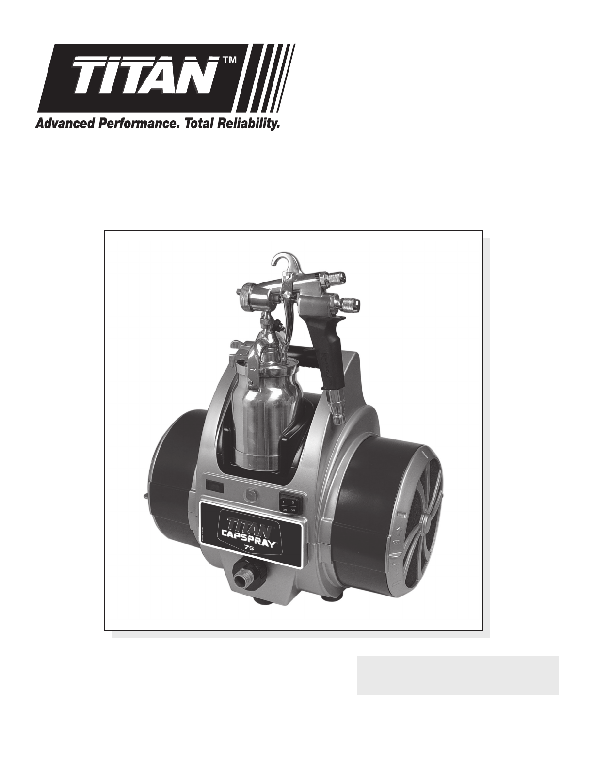
CAPSPRAY 75
HVLP Spray System
Model
0524031
Register your product online at:
www.titantool.com
Serial Number* _ _ _ _ _ _ _ _ _ _
* See page 5 for location
NOTE: This manual contains important
warnings and instructions. Please read
and retain for reference.
0115 • © Titan Tool Inc. All Rights Reserved. Form No. 0524856G
Page 2
Important Safety Information
Grounded Outlet
Grounding Pin
Cover for grounded outlet box
Read all safety information before operating the
equipment. Save these instructions.
Indicates a hazardous situation which, if not avoided,
could result in death or serious injury.
To reduce the risks of re or explosion, electrical shock
and the injury to persons, read and understand all
instructions included in this manual. Be familiar with the
controls and proper usage of the equipment.
Grounding Instructions
This product must be grounded. In the event of an electrical short circuit,
grounding reduces the risk of electric shock by providing an escape wire for
the electric current. This product is equipped with a cord having a grounding
wire with an appropriate grounding plug. The plug must be plugged into
an outlet that is properly installed and grounded in accordance with all local
codes and ordinances.
WARNING - Improper installation of the grounding plug
can result in a risk of electric shock.
If repair or replacement of the cord or plug is necessary, do not connect the
green grounding wire to either at blade terminal. The wire with insulation
having a green outer surface with or without yellow stripes is the grounding
wire and must be connected to the grounding pin.
Check with a qualied electrician or serviceman if the grounding instructions
are not completely understood, or if you are in doubt as to whether the
product is properly grounded. Do not modify the plug provided. If the plug
will not t the outlet, have the proper outlet installed by a qualied electrician.
IMPORTANT: Use only a 3-wire extension cord that has a 3-blade
grounding plug and a 3-slot receptacle that will accept the plug on the
product. Make sure the extension cord is in good condition. When
using an extension cord, be sure to use one heavy enough to carry the
current the product will draw. An undersized cord will cause a drop
in line voltage resulting in loss of power and overheating. A 12 gauge
cord is recommended. If an extension cord is to be used outdoors, it
must be marked with the suffix W-A after the cord type designation. For
example, a designation of SJTW-A would indicate that the cord would be
appropriate for outdoor use.
NOTE: More than 100 feet of extension cord is not recommended.
PREVENTION:
• Read all instructions and safety precautions before operating any
• Follow all appropriate local, state, and national codes governing
• The United States Government Safety Standards have been adopted
• Use only manufacturer authorized parts. User assumes all risks
• Before each use, check all hoses for cuts, leaks, abrasion or bulging
2 © Titan Tool Inc. All rights reserved.
Use more hose, not more extension cord. Shorter extension
cords will assure maximum electrical power for proper
operation.
HAZARD: GENERAL
Can cause severe injury or property damage.
equipment.
ventilation, re prevention, and operation.
under the Occupational Safety and Health Act (OSHA). These
standards, particularly Part 1910 of the General Standards and Part
1926 of the Construction Standard should be consulted.
and liabilities when using parts that do not meet the minimum
specications and safety devices of the manufacturer.
of cover. Check for damage or movement of couplings. Immediately
replace the hose if any of these conditions exist. Never repair a hose.
Replace it with an identical replacement hose.
• Do not spray outdoors on windy days.
• Wear clothing to keep paint o skin and hair.
• Never aim the spray gun at any part of the body.
HAZARD: EXPLOSION HAZARD DUE TO
INCOMPATIBLE MATERIALS
Will cause property damage or severe injury.
PREVENTION:
• Do not use materials containing bleach or chlorine.
• Do not use halogenated hydrocarbon solvents such as bleach,
mildewcide, methylene chloride and 1,1,1 - trichloroethane. They are
not compatible with aluminum.
• Contact your coating supplier about the compatibility of material with
aluminum.
HAZARD: EXPLOSION OR FIRE
Solvent and paint fumes can explode or ignite. Property
damage and/or severe injury can occur.
PREVENTION:
• Exhaust and fresh air introduction must be provided to keep the air
within the spray area free from accumulation of ammable vapors.
• Turbine contains sparking parts. Turbine must be placed in a well
ventilated area at maximum distance from the spray area.
• Avoid all ignition sources such as static electricity, open ames,
pilot lights, hot objects, cigarettes, and sparks from connecting and
disconnecting power cords and working light switches.
• Use extreme caution when using materials with a ashpoint below
100° F (38°C). A uid’s ashpoint is the temperature at which vapors
from the uid could ignite if exposed to a ame or spark.
• Fire extinguishing equipment must be present and in working order.
• The power cord must be connected to a grounded circuit.
• Follow the material and solvent manufacturer’s safety precautions and
warnings.
HAZARD: HAZARDOUS VAPORS
Paints, solvents, insecticides, and other materials can
be harmful if inhaled or come in contact with the body.
Vapors can cause severe nausea, fainting, or poisoning.
PREVENTION:
• Use a respirator or mask if vapors can be inhaled. Read all instructions
supplied with the mask to be sure it will provide the necessary
protection.
• Wear protective eyewear.
• Wear protective clothing as required by coating manufacturer.
HAZARD: SKIN BURN INJURY
Heated parts can cause severe skin burn injury.
PREVENTION:
• Quick disconnect ttings on the hose and spray gun become hot
during use. Avoid skin contact with quick disconnect ttings
when they are hot. Allow quick disconnect ttings to cool before
disconnecting the spray gun from the hose.
Service
Should your spray system need service during the warranty period,
return your unit and the proof of purchase to the distributor where it was
purchased. At our option, the unit will be repaired or replaced. In a continued
commitment to improve quality, we reserve the right to make component or
design changes when necessary.
English
Page 3
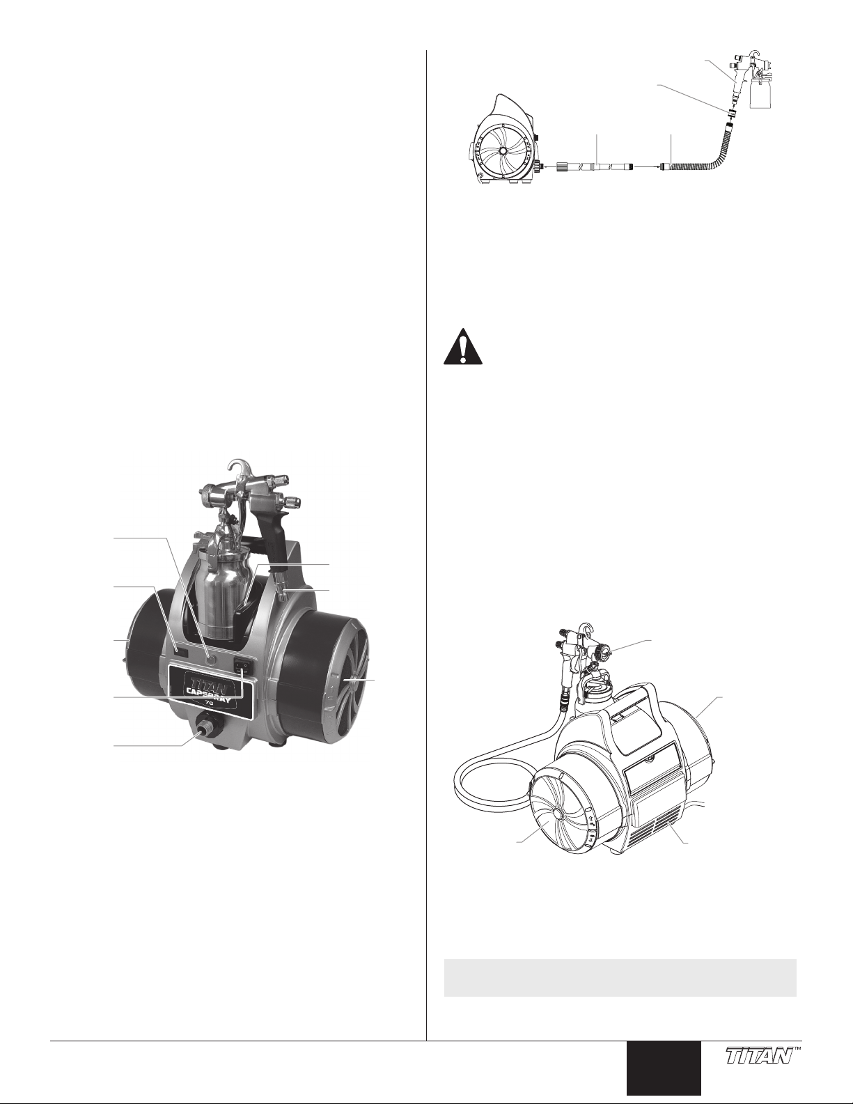
Table of Contents
*Air hose not pictured
ilter
Air outlet
(in end of
lter can)
discharge
Atomizing air
Rear of turbine
Safety ................................................................................................ 2
Grounding Instructions ................................................................................. 2
Service .............................................................................................. 3
Introduction ..................................................................................... 3
Using an HVLP Spray System .......................................................... 3
Setup .................................................................................................................... 3
Dual Filtration System .................................................................................... 3
Maintenance .................................................................................... 4
Cleaning/Replacing Filters ........................................................................... 4
Cleaning the Air Hoses ................................................................................... 4
Troubleshooting .............................................................................. 5
Product Registration ....................................................................... 5
Français ............................................................................................ 6
Español ........................................................................................... 10
Parts List ....................................................................................14-17
Wiring Diagram ............................................................................. 18
Warranty ........................................................................................ 20
Introduction
This High Volume/Low Pressure (HVLP) spray system is designed
for applying coatings to surfaces that can be sprayed faster than
brushing or rolling and are too small for traditional airless sprayers.
Components of this system include a power switch, a power cord, a
lter warning light, a circuit breaker switch, a dual ltration system, a
cup holder, an air hose, and an air outlet.
The turbine is also equipped with a tool box. It is located on the
reverse side of the turbine and can be used to store projector sets or
any other small spare parts.
Spray gun
Turbine
IMPORTANT: Do not attach the short air whip hose directly to
the turbine, as the hose will become damaged.
Air hose
Coupling
Whip hose
Setup
Use the following procedure to set up your HVLP spray system for
operation.
1. Plug the turbine power cord into a grounded, 3-slot
receptacle.
Keep the turbine at the maximum possible distance
from the spray area to safeguard against explosion or
fire that may be caused by sparking electrical parts.
2. Prepare your spray gun for operation. Refer to your spray
gun manual for material preparation, setup, and spraying
information.
3. Attach the air hose to the air outlet on the turbine.
4. Attach the air hose to the air inlet on your spray gun.
5. Turn on the turbine and begin spraying.
breaker
warning
With this HVLP spray system, you can achieve the highest quality
professional nish possible with little or no preparation or setup time.
Please review all the information contained in this manual before
operating the system.
Using an HVLP Spray System
Refer to the following information to operate and understand your
HVLP spray system.
Your system may include a short air (“whip”) hose. The short hose
should be connected to the longer hose or a remote spraying system
(sold separately) and NOT directly to the turbine. See your spray gun
instruction manual for complete instructions.
© Titan Tool Inc. All rights reserved. 3
Circuit
switch
Filter
light
Filter
Power
switch
Cup holder
Air inlet
Dual Filtration System
The turbine has two dierent air lters— one for atomizing air and
one for cooling air. The atomizing air lter is a two-stage, ne mesh
lter designed to trap particles that may damage your nish. The
atomizing air is discharged through the nozzle of the spray gun
where it atomizes the coating material. The cooling air lter is a
coarse mesh lter designed to allow the proper amount of air ow
through the turbine for cooling purposes. Cooling air is exhausted
through the cooling air discharge on the front of the turbine.
Atomizing air
discharge
F
intake
Cooling air
intake
Filter Warning System
The lter warning system on your turbine consists of a red lter
warning light on the front control panel and an air ow switch inside
the turbine. When the air ow switch does not detect the appropriate
amount of air owing through the turbine, the lter warning light will
come on to indicate that it is time to clean or change the lters.
NOTE: The lter warning system does not shut down the
turbine.
IMPORTANT: Clean filters regularly. Clogged filters can cause
excessive heat and possibly damage the turbine.
Cooling air
English
Page 4
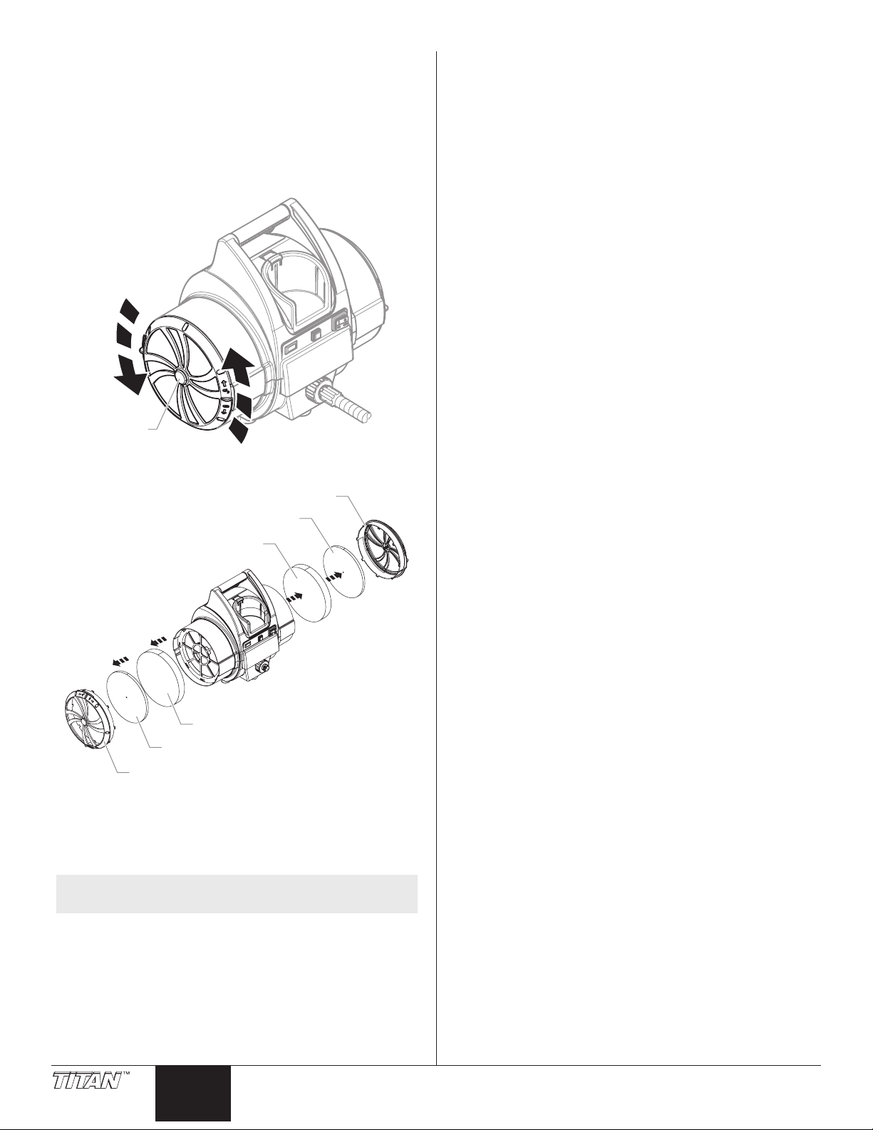
Maintenance
F
Filter cover
Filter cover
Use the following procedures to keep your HVLP spray system
running properly.
Cleaning / Replacing the Filters
IMPORTANT: Make sure the turbine is unplugged before
changing the filters.
1. Remove the lter covers on each side of the turbine by
turning them counterclockwise.
ilter cover
2. Remove each lter set (pre-lter and lter) from the lter
housing on each side of the turbine.
Cleaning the Air Hoses
1. Periodically wipe the outer surface of the air hose with a damp
cloth to keep clean.
IMPORTANT: DO NOT submerge into or flush the air hose with
water or any chemical.
IMPORTANT: DO NOT use methylethylketon (MEK), naphtha,
mineral spirits, paint thinner, xylol/xylene, or toluel/toluene to
clean the air hose. Exposure over time could cause damage to
the hose.
IMPORTANT: Store indoors with the cord wrapped around the
handle.
Pre-lter
Filter
Filter
Pre-lter
3. Clean the lters. Either tap the lters to knock out the
contaminants or use pressurized air to blow out the
contaminants. For material that is not blown or knocked loose
easily, soak the lters in soapy water or mineral spirits. Allow
the lters to dry completely before placing them back in the
turbine.
NOTE: Do not use highly ammable solvents, such as
lacquer thinner, to clean the lters.
4. Insert each lter back into its corresponding lter can.
5. Replace the lter covers on each side of the turbine by turning
them clockwise.
After several cleanings, it may become necessary to replace the
lters. Refer to the parts list near the end of this manual for the lter
replacement kit part number.
4 © Titan Tool Inc. All rights reserved.
English
Page 5
Troubleshooting
xxxxxxx
Problem
A. Restricted air ow or no air ow
B. Filter warning light is on
C. The turbine has no power
D. Excessive arcing/sparking in the
turbine
Cause
1. Air ow adjustment knob on the spray gun is
turned o
2. Air lters are clogged
1. Air lters are clogged
1. No power at the power supply
2. Circuit breaker has been tripped.
3. Worn turbine brushes
1. Worn turbine brushes
2. Damaged commutator
IMPORTANT:
• The turbine motor can be damaged if not serviced properly.
Have the brushes (Kit P/N 0277243) checked for wear by an
authorized service center every 400 hours.
• Clean lters regularly. When the lter warning light comes
on, it is time to clean the lters. Clogged lters cam cause
excessive heat and possibly damage the unit.
• For additional troubleshooting information, see the manual
that came with your gun.
Solution
1. Adjust the air ow adjustment knob
2. Clean or replace the lters
1. Clean or replace the lters
1. Check the power supply
2. Reset the breaker. If problem persists, have turbine
inspected at an authorized Titan service center.
3. Have the brushes replaced at an authorized Titan service
center
1. Have the brushes replaced at an authorized Titan service
center
2. Replace the turbine (contact a Titan service technician)
Product Registration
Register your product at www.titantool.com
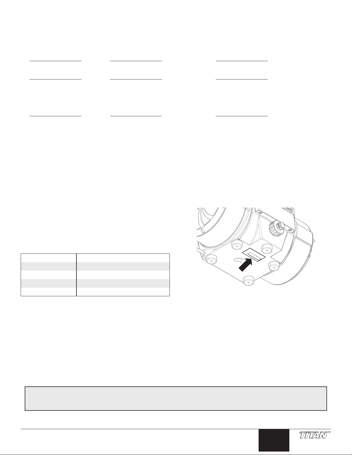
Serial Number Location
Specications
Air pressure 7.5 psi
Power 120VAC, 60 Hz, 10.7 A
Turbine weight 21.0 lbs
Main hose length 25 ft
Spray gun included Maxum II
Titan 30-Day Satisfaction Guarantee
If, within a 30-day period from the date of purchase, you are not totally satised with a TITAN unit, you may return it for full credit toward
another TITAN product of equal or greater value.
© Titan Tool Inc. All rights reserved. 5
English
Page 6
Consignes de sécurite important
Prise trilaire
Broche de mise à la terre
Plaque murale de la prise
Lire toutes ces consignes avant d’utiliser l’appareil.
Garder ces consignes.
Indique une situation à risque, laquelle, si elle n’est pas évitée,
peut entraîner des blessures graves, voire la mort.
Pour réduire les risques d’incendie ou d’explosion, de choc
électrique et de blessure, vous devez lire et comprendre les
directives gurant dans ce manuel. Familiarisez-vous avec les
commandes et l’utilisation adéquate de l’équipement.
Instructions de mise à la terre
Cet appareil doit être mis à la terre. La mise à la terre réduit les risques
d’électrocution lors d’un court-circuit en permettant au courant de s’écouler
par le l de mise à la terre. Cet appareil est muni d’un cordon électrique avec
l de mise à la terre ainsi que d’une che de terre. La che doit être branchée
sur une prise installée correctement et mise à la terre conformément à la
réglementation et aux codes en vigueur.
MISE EN GARDE - Le fait de ne pas brancher correctement la
che trilaire de l’appareil peut entraîner des risques de choc
électrique.
S’il s’avère nécessaire de réparer ou de remplacer le cordon électrique ou la
che, ne pas brancher le l vert de mise à la terre sur l’une ou l’autre des bornes
à broche plate. Le l recouvert d’un isolant vert avec ou sans rayures jaunes est
le l de mise à la terre et doit être branché sur la broche de mise à la terre.
Si vous ne comprenez pas les instructions de mise à la terre ou si vous n’êtes
pas sûr que l’appareil est correctement mis à la terre, contactez un électricien
agréé. Ne pas modier la che d’origine. Si la prise ne convient pas à la che,
faites installer la prise adéquate par un électricien agréé.
IMPORTANT : Utiliser uniquement une rallonge à trois fils munie d’une
fiche de terre dans une prise secteur mise à la terre correspondant au
type de fiche de l’appareil. S’assurer que votre rallonge est en bon
état. Lorsque vous utilisez une rallonge, assurez-vous qu’elle soit d’un
calibre suffisant pour supporter l’intensité du courant requise par
l’appareil. Une rallonge trop mince entraîne une chute de tension, une
diminution de l’intensité et une surchauffe. Une rallonge de calibre 12 est
recommandée. Si vous devez utiliser une rallonge à l’extérieur, celle-ci
doit comprendre la marque W-A après la désignation indiquant le type
de cordon. Par exemple, la désignation SJTW-A indique que le cordon est
conçu pour être utilisé à l’extérieur.
NOTA : On ne recommande pas l’utilisation de rallonges de plus
PRÉVENTION :
• Lire toutes les directives et mises en garde avant de faire fonctionner
• Se conformer à la législation locale, provinciale ou fédérale pour
• Les normes de sécurité adoptées par le gouvernement américain l’ont
• N’utiliser que les pièces autorisées par le fabricant. L’utilisateur
• Vérier, avant toute utilisation, que les exibles ne présentent pas
6 © Titan Tool Inc. Tous droits réservés.
de 30 m (100 pi); il est préférable de rallonger le tuyau
que le cordon d’alimentation. Les rallonges plus courtes
assureront la puissance électrique requise pour un
fonctionnement adéquat.
DANGER : GÉNÉRAUX
Risques de dommages matériels et de blessures graves.
l’équipement, quel qu’il soit.
tout ce qui concerne la ventilation, la prévention des incendies et les
conditions générales d’utilisation.
été en vertu de sa Occupational Safety and Health Act (OSHA); ces
normes, particulièrement les parties 1910 des normes générales et
1926 des normes de construction, devraient toujours être consultées.
assume tous les risques et responsabilités lorsqu’il utilise des pièces
qui ne sont pas conformes aux caractéristiques techniques minimales
ainsi qu’aux dispositifs de sécurité du fabricant.
d’entaille ou de fuite, que le couvercle ne soit pas goné et que les
raccords ne soient pas endommagés. Si le exible a subi l’un des
dommages précités, remplacez-le immédiatement. Ne jamais réparer
un exible d’alimentation. Le remplacer avec un exible identique de
remplacement.
• Ne jamais pulvériser lorsqu’il vente.
• Porter des vêtements pour protéger la peau et les cheveux contre tout
contact avec la peinture.
• On ne doit jamais orienter le pistolet vers une partie du corps.
DANGER : RISQUES D’EXPLOSION PAR INCOMPATIBILITÉ
DES MATÉRIAUX
Peuvent être à l’origine de corporels sérieux ou dommages matériels.
PRÉVENTION :
• Ne pas utiliser de matériaux contenant des agents de blanchiment ou
du chlore.
• Ne pas utiliser des solvants à base d’hydrocarbure halogéné tels que
l’agent anticryptogamique, le chlorure de méthylène et le trichloroéthane-1,1,1. Ces produits ne sont pas compatibles avec l’aluminium.
• Communiquer avec votre fournisseur de revêtement pour connaître la
compatibilité du matériau avec l’aluminium.
DANGER : RISQUES D’EXPLOSION OU D’INCENDIE
Les vapeurs dégagées par le solvant ou la peinture sont
explosives et inammables et peuvent causer des corporels
sérieux ou dommages matériels.
PRÉVENTION :
• Veiller à éviter toute accumulation de vapeurs inammables en vous
assurant que la zone où la pulvérisation a lieu est susamment ventilée.
• Veiller à éviter la présence de toute source incandescente telle
qu’étincelle électrostatique, amme nue, amme-pilote, objet brûlant,
cigarette et étincelle provenant du branchement ou du débranchement
d’un cordon d’alimentation électrique ou d’un commutateur.
• Ne pas fumer dans la zone d’épandage.
• Toujours avoir un extincteur en état de fonctionner à portée de la main.
• Le cordon d’alimentation doit être raccordé à un circuit mis à la terre.
• S’assurer de suivre les directives en matière de sécurité et de lire les mises
en garde du fabricant des solvants et des produits utilisés.
• S’entourer de toutes les précautions possibles lorsqu’on utilise des
produits ayant un point d’éclair inférieur à 38 °C (100 °F). Le point
d’éclair d’un uide est la température à laquelle les vapeurs émanant du
uide peuvent s’enammer au contact d’une amme ou d’une étincelle.
• Le plastique peut être une source d’étincelles provoquées par
l’électricité statique. Ne jamais utiliser une couverture en plastique
pour fermer une zone d’épandage ni utiliser des toiles de protection en
plastique lors de la pulvérisation de matières inammables.
DANGER : VAPEURS NOCIVES
La peinture, les solvants, les insecticides et autres matériaux
peuvent être nocifs lorsqu’ils sont inhalés ou en contact avec le
corps. Les vapeurs peuvent causer une nausée importante, des
évanouissements ou un empoisonnement.
PRÉVENTION :
• Utiliser un respirateur ou un masque chaque fois qu’il y a des risques
d’inhalation de vapeurs. Lire attentivement toutes les instructions
se rapportant au masque pour vérier que celui-ci vous assure une
protection susante contre les vapeurs toxiques.
• Porter des lunettes de protection.
• Porter des vêtements de protection, conformément aux directives du
fabricant de revêtement.
DANGER : DANGER DE BRÛLURE
Les pièces chauées peuvent causer de graves brûlures cutanées.
PRÉVENTION :
• Les raccords à dégagement rapide du tuyau exible et du pistolet
peuvent s’échauer en cours d’utilisation; il faut alors éviter les
contacts cutanés, en attendant que les raccords refroidissent avant de
séparer le pistolet du tuyau.
Français
Page 7

Entretien et Réparations
*Tuyau pour l’air pas d’illustration
e
C
de refroidissement
refroidissemen
n
Si le système requiert de l’entretien ou des réparations pendant la période
de la garantie, on doit le retourner, accompagné d’une preuve d’achat, au
distributeur chez qui on l’a acheté. Il sera alors, selon le choix du fabricant,
réparé ou remplacé. Dans le cadre de son engagement perpétuel envers
l’amélioration de la qualité, nous réservons le droit de modier les composants
ou la conception de ses produits si elle le juge nécessaire.
du pistolet pulvérisateur pour des instructions complètes.
Pistolet
Turbine
Tuyau d’air
Raccord
Tuyau
d’arrivée
Table des matières
Sécurité............................................................................................. 6
Instructions pour la mise à la terre ............................................................ 6
Entretien et Réparations ................................................................. 6
Introduction ..................................................................................... 7
Utilisation d’un système de vaporisation HVLP............................ 7
Préparation ........................................................................................................7
Système de double ltration ....................................................................... 7
Maintenance .................................................................................... 8
Nettoyage/remplacement des ltres ....................................................... 8
Nettoyage le tuyau pour l’air ....................................................................... 8
Recherche des pannes ..................................................................... 9
Enregistrement du produit ............................................................. 9
Liste de pièces .......................................................................... 14–17
Diagramme électrique .................................................................. 18
Garantie .......................................................................................... 19
Introduction
Ce système de vaporisation “High Volume/Low Pressure (HVLP)
(volume élevé/basse pression) est conçu pour l’application de
revêtements sur des surfaces qui peuvent être peintes plus
rapidement qu’avec un pinceau ou un rouleau et qui sont trop petites
pour permettre l’utilisation des vaporisateurs sans air traditionnels.
Le système comprend les composants suivants : un interrupteur
d’alimentation, un câble d’alimentation, une lampe témoin de
ltre, un commutateur de briseur de circuit, un système de double
ltration, un support de godet, un boyau pour l’air et une sortie d’air.
La turbine est également munie d’une trousse d’outils. Elle est située
sur le revers de la turbine et peut servir à ranger les jeux de gicleur ou
autres petites pièces de rechange.
ommutateur
de briseur
de circuit
Lampe
témoin
de ltre
Filtre (à
l'extrémité
du carter de
ltre)
Interrupteur
Sortie d’air
Grâce à ce système HVLP, il est possible d’obtenir une très haute
qualité professionnelle avec peu de préparation et de temps de
réglage. Veuillez SVP consulter toutes les informations contenues
dans ce manuel avant de faire fonctionner le système.
Support
de godet
Entrée d’air
Filtr
Utilisation d’un système de vaporisation HVLP
Se reporter aux informations suivantes pour faire fonctionner et bien
assimiler le système de vaporisation HVLP.
Il est possible que votre système comprenne un tuyau court pour l’air
(« tuyau d’arrivée »). Le tuyau court devrait être raccordé au tuyau
long ou à un système de pulvérisation éloigné (vendu séparément) et
NON directement à la turbine. Reportez-vous à votre mode d’emploi
© Titan Tool Inc. Tous droits réservés. 7
IMPORTANT : Ne raccordez pas le tuyau court d’arrivée d’air
directement à la turbine, car cela endommagera le tuyau.
Préparation
Utiliser la procédure suivante pour préparer à faire fonctionner le
système de vaporisation HVLP.
1. Brancher le câble d’alimentation de la turbine dans une prise
électrique à 3 broches équipée d’une mise à la terre.
Maintenir la turbine aussi éloignée que possible de la
zone de vaporisation, de manière à éviter tout incendie
ou explosion provoqué par les pièces produisant des
étincelles.
2. Préparer à faire fonctionner le pistolet de vaporisation. Se
reporter au manuel du pistolet de vaporisation pour les
informations concernant la préparation de l’équipement, le
réglage et la vaporisation.
3. Raccorder le boyau pour l’air à la sortie d’air de la turbine.
4. Raccorder le boyau pour l’air à l’entrée d’air du pistolet de
vaporisation.
5. Mettre en marche la turbine et commencer à vaporiser.
Système de double ltration
La turbine comporte deux ltres à air diérents — un pour
l’atomisation de l’air et l’autre pour le refroidissement de l’air. Le ltre
à air pour l’atomisation est un ltre à mailles n à deux étages conçu
pour piéger les particules néfastes à la qualité de la nition. L’air
d’atomisation est évacué à travers la buse du pistolet de vaporisation
où il atomise le matériau du revêtement. Le ltre à air pour le
refroidissement est un ltre à mailles grossier conçu pour permettre
un débit d’air de refroidissement approprié à travers la turbine. L’air de
refroidissement est évacué par l’échappement d’air de refroidissement
situé à l’avant de la turbine.
Echappement air
Vue arrière
Entrée air de
t
Système d’avertissement de ltre
Le système d’avertissement du ltre de la turbine comporte une
lampe témoin de ltre rouge sur le panneau de commande frontal
et un commutateur de débit d’air à l’intérieur de la turbine. Lorsque
le commutateur de débit d’air ne détecte pas le débit d’air approprié
devant circuler à travers la turbine, la lampe témoin s’allume pour
indiquer qu’il est temps de nettoyer ou de changer les ltres.
NOTA : Le système d’avertissement du ltre n’arrête pas le
fonctionnement de la turbine.
IMPORTANT : Nettoyer régulièrement les filtres. Les filtres
engorgés peuvent engendrer une surchauffe et peut-être
endommager l’unité.
d'atomisation
Entrée air
d'atomisatio
Echappement air
Français
Page 8

Maintenance
Ca
Carter du ltre
Carter du ltre
Utiliser la procédure suivante pour maintenir votre pistolet de
vaporisation HVLP en bon état de fonctionnement.
Nettoyage/remplacement des ltres
MPORTANT : Assurez-vous que la turbine est débranchée avant
de changer les filtres.
1. Enlevez les couvercles de ltre de chaque côté de la turbine en
les tournant dans le sens contraire des aiguilles d’une montre.
Nettoyage le tuyau d’air
1. Essuyer périodiquement la surface externe des tuyau d’air
avec un chion humide pour maintenir propre.
IMPORTANT : Ne pas submerger ou ne pas rincer les tuyau d’air
avec l’eau ou aucun produit chimique.
IMPORTANT : Ne pas nettoyer ce tuyau à l’aide de butanone,
de naphta, d’essence minérale, de diluant ou de xylol. Une
exposition prolongée à ces produits pourrait l’endommager.
IMPORTANT : Rangez à l’intérieur d’un bâtiment avec le cordon
d’alimentation enroulé autour de la poignée.
rter du ltre
2. Enlevez chaque jeu de ltre (préltre et ltre) du boîtier du
ltre de chaque côté de la turbine.
Préltre
Filtre
Filtre
Préltre
3. Nettoyer les ltres. Donner des petits coups sur les ltres
pour évacuer les contaminants ou utiliser de l’air comprimé
pour les chasser. Pour les matières qui ne sont pas évacuées
facilement, tremper les ltres dans de l’eau savonneuse ou
dans de l’essence minérale. Laisser sécher complètement les
ltres avant de les remonter dans la turbine.
NOTA: Pour nettoyer les ltres, ne pas utiliser de solvants
IMPORTANT : Ne laissez pas tremper le filtre de papier plissé
dans des solvants. Tapotez seulement le filtre ou utilisez de l’air
comprimé en le dirigeant à l’intérieur (côté propre).
4. Remonter chaque ltre dans son carter correspondant.
5. Replacez les couvercles de ltre de chaque côté de la turbine
Après plusieurs nettoyages, il peut devenir nécessaire de remplacer
les ltres. Se reporter à la liste de pièces à la n de ce manuel pour la
référence de l’ensemble de remplacement de ltre.
8 © Titan Tool Inc. Tous droits réservés.
hautement inammable tels que les diluants à
peinture-laque.
en les tournant dans le sens des aiguilles d’une montre.
Français
Page 9

Recherche des pannes
xxxxxxx
Problème
A. Débit d’air restreint ou aucun
débit d’air
B. La lampe témoin de ltre est
allumée
C. La turbine n’a pas de puissance
D. Production excessive d’arcs
électriques/étincelles dans la
turbine
Cause
1. Le bouton de réglage de débit d’air sur le
pistolet de vaporisation est fermé
2. Les ltres à air sont colmatés
1. Les ltres à air sont colmatés
1. Pas d’alimentation électrique
2. Le disjoncteur a été déclenché.
3. Les balais de la turbine sont usés
1. Les balais de la turbine sont usés
2. Le commutateur est endommagé
IMPORTANT :
• Le moteur de la turbine peut être endommagé si on n’en
eectue pas l’entretien approprié. Faire vérier l’usure des
brosses (N/P 0277243) par un centre d’entretien autorisé à
toutes les 400 heures d’utilisation.
• Nettoyer régulièrement les ltres. Si le voyant lumineux
s’allume, c’est qu’il est temps d’y voir. Les ltres engorgés
peuvent engendrer une surchaue et peut-être endommager
l’unité.
• Pour obtenir de plus amples renseignements en matière de
diagnostic des anomalies, consulter le manuel accompagnant
le pistolet.
Solution
1. Ajuster le bouton de réglage de débit d’air
2. Nettoyer ou remplacer les ltres
1. Nettoyer ou remplacer les ltres
1. Vérier l’alimentation électrique
2. Retournez le disjoncteur à sa position enclenchée. Si le
problème ne se règle pas, faites inspecter la turbine à un
centre de service autorisé Titan.
3. Faire remplacer les balais par un centre de service agréé
Titan
1. Faire remplacer les balais par un centre de service agréé
Titan
2. Remplacer la turbine (contacter un technicien Titan)
Enregistrement du produit
Enregistrer votre appareil en ligne à www.titantool.com.
Emplacement du numéro de série
Spécications
Pression d’air 7,5 psi
Alimentation 120VAC, 60 Hz, 15 A
Poids de la turbine 9,52 kg
Longueur du tuyau principal 7,62 m
Pistolet compris Maxum II
Garantie de satisfaction 30 jours de Titan
Si, au cours des 30 jours suivant l’achat, vous n’êtes pas totalement satisfait d’un appareil TITAN, vous pouvez le renvoyer et obtenir un
crédit complet contre un autre produit TITAN de valeur égale ou supérieure.
© Titan Tool Inc. Tous droits réservés. 9
Français
Page 10

Información de seguridad importante
Receptáculo conectado a tierra
Lea toda la información de seguridad antes de
operar el equipo. Guarde estas insturcciones.
Indica una situación peligrosa que, de no evitarse, puede
causar la muerte o lesiones graves.
Para reducir los riesgos de incendios, explosiones, descargas
eléctricas o lesiones a las personas, lea y entienda todas las
instrucciones incluidas en este manual. Familiarícese con los
controles y el uso adecuado del equipo.
Instrucciones para conectar a tierra
Este producto se debe conectar a tierra. En caso de que ocurra un corto
circuito, la conexión a tierra reduce el riesgo de choque eléctrico al
proporcionar un alambre de escape para la corriente eléctrica. Este producto
está equipado con un cable que tiene un alambre de conexión a tierra con un
enchufe de conexión a tierra apropiado. El enchufe se debe enchufar en una
toma de corriente que se haya instalado y conectado a tierra debidamente, de
acuerdo con todos los códigos y estatutos locales.
ADVERTENCIA - La instalación incorrecta del enchufe a tierra
puede ocasionar un riesgo de choque eléctrico.
Si es necesario reparar o reemplazar el cable o el enchufe, no conecte el
alambre de conexión a tierra a ninguno de los terminales de hoja planos.
El alambre con aislamiento que tiene la supercie exterior de color verde
con franjas amarillas o sin ellas es el alambre de conexión a tierra que debe
conectarse al conector de conexión a tierra.
Verique con un electricista o técnico de servicio calicado si las instrucciones
para conectar a tierra no le han quedado completamente claras, o si duda
que el producto haya quedado conectado a tierra de manera apropiada. No
modique el enchufe que se proporciona. Si el enchufe no entra en la toma
de corriente, pídale a un electricista calicado que instale la toma apropiada.
IMPORTANTE: Use solamente extensiones trifilares que tengan un
enchufe de conexión a tierra de 3 hojas y un receptáculo de triple ranura
que acepte el enchufe del producto. Asegúrese de que su extensión esté
en buenas condiciones. Cuando use una extensión, asegúrese de usar una
que sea lo suficientemente resistente como para soportar la corriente que
descargue su producto. Un cable de un tamaño menor causará una caída
de voltage en la línea que dará como resultado una pérdida de energía y
un sobrecalenta|ôento. Se recomienda usar un cable de calibre 12. Si se
utiliza un cable de extensión en el exterior, tiene que estar marcado con
el sufijo W-A después de la designación del tipo de cable. Por ejemplo,
SJTW-A para indicar que el cable es apropiado para uso en exteriores.
NOTA : No se recomienda usar una extensión de más de 100 pies.
PREVENCIÓN:
• Lea todas las instrucciones y advertencias de seguridad antes de hacer
• Observe todos los códigos locales, estatales y nacionales apropiados
• Los Estándares de Seguridad del Gobierno de los Estados Unidos se
• Utilice únicamente piezas autorizadas por el fabricante. El usuario
10 © Titan Tool Inc. Todos los derechos reservados.
Use una longitud mayor de manguera de pintura, no una
extensión más larga. Una extensión más corta asegurará
que haya la energía eléctrica máxima para tener un
funcionamiento apropiado.
PELIGRO: GENERAL
Puede causar daños en la propiedad o lesiones severas.
funcionar cualquier equipo.
que rigen las medidas de ventilación, prevención de incendios y
operación.
han adoptado bajo el Decreto de Seguridad y Salud Ocupacionales
(OSHA por sus siglas en inglés). Deben consultarse estos estándares,
particularmente la parte 1910 de los Estándares Generales y la parte
1926 de los Estándares de la Construcción.
asume todos los riesgos y responsabilidades si usa piezas que no
cumplen con las especicaciones mínimas y dispositivos de seguridad
del fabricante.
Pata a tierra
• Antes de usarla cada vez, revise todas las mangueras para ver que
no tengan cortadas, fugas, una cubierta desgastada por abrasión o
con abolladuras, así como uniones dañadas o que se hayan movido.
Si existiera cualquiera de estas condiciones, reemplace la manguera
inmediatamente. No repare nunca una manguera. Reemplazar lo con
una manguera idéntica de reemplazo.
• No atomice en días con viento.
• Use ropa que evite el contacto de la pintura con la piel y el cabello.
• Nunca apunte la pistola hacia alguna parte del cuerpo.
PELIGRO: POSIBLE EXPLOSIÓN DEBIDO A MATERIALES
INCOMPATIBLES
Causará daños materiales o lesiones graves.
PREVENCIÓN:
• No use materiales que contengan blanqueador o cloro.
• No use solventes de hidrocarburos halogenados como blanqueador,
mohocida, cloruro de metileno y 1,1,1 tricloroetano. No son
compatibles con el aluminio.
• Diríjase al proveedor de revestimientos para obtener los datos de
compatibilidad del material con el aluminio.
PELIGRO: INCENDIO O EXPLOSIÓN
Los vapores de los solventes y pinturas pueden explotar o
encenderse y causar con esto daños en la propiedad y/o lesiones
severas.
PREVENCIÓN:
• Se deberá contar con un escape y entrada de aire fresco para
mantener el aire del área de atomización libre de acumulaciones de
vapores inamables.
• La turbina contiene partes que producen chispa. La turbina debe colocarse
en un área bien ventilada a distancia máxima del área de pintado.
• Evite que haya cualquier fuente de ignición como la electricidad
estática, llamas abiertas, amas de pilotos, objetos calientes, cigarros y
chispas que provengan de conectar y desconectar cables de energía e
interruptores de luces que estén funcionando.
• Tenga muchísimo cuidado al usar materiales cuyo punto de ignición
sea inferior a 100° F (38° C). El punto de ignición es la temperatura
a la cual pueden encenderse los vapores emanados por un uido al
exponerlos a llamas o chispas.
• Debe haber equipo para extinción de incendios que además funcione bien.
• El cable de energía debe conectarse en un circuito que esté conectado
a tierra.
• Siga las medidas de precaución y advertencias de seguridad del
fabricante del material y del solvente.
PELIGRO: GASES PELIGROSOS
Las pinturas, solventes, insecticidas y otros materiales pueden ser
perjudiciales si se inhalan o entran en contacto con el cuerpo. Los
gases pueden causar náusea, desmayos o envenenamiento graves.
PREVENCIÓN:
• Use una mascarilla respiratoria o careta siempre que exista la
posibilidad de que se puedan inhalar vapores. Lea todas las
intrucciones que vengan con la careta para estar seguro de que se
tendrá la protección necesaria contra la inhalación de vapores dañinos.
• Use gafas protectoras.
• Use ropa de protección, según lo requiera el fabricante del producto.
PELIGRO: QUEMADURA DE LA PIEL
Las piezas calientes pueden causar lesiones de quemadura de la
piel severas.
PREVENCIÓN:
• Las conexiones de desconexión rápida de la manguera y la pistola de
atomización se llegan a calentar mientras se usan. Evite que la piel
tenga contacto con las conexiones de desconexión rápida cuando se
calienten. Deje que las conexiones de desconexión rápida se enfríen
antes de desconectar la pistola de atomización de la manguera.
Español
Page 11

*Manguera de aire no muestra
o
ex
aire de enfriamiento
A
misión de aire
Servicio
Si su pistola necesitara recibir servicio durante el periodo de garantía,
devuelva la pieza y la prueba de compra al distribuidor donde la compró.
Nosotros decidiremos si la reparamos o la reemplazamos. Por el compromiso
continuo que se tiene de mejorar la calidad, nosotros reservamos el derecho
de hacer cambios de componentes o diseño cuando sea necesario.
Indice
Seguridad ....................................................................................... 10
Instrucciones para Aterrizar .......................................................................10
Servicio ........................................................................................... 10
Introducción ................................................................................... 11
Cómo usar un sistema de atomización HVLP .............................. 11
Preperación ......................................................................................................11
Sistema doble de ltration .........................................................................11
Mantenimiento .............................................................................. 12
Limpieza/cambio de ltros .........................................................................12
Limpieza la manguera de aire ...................................................................12
Solución de problemas ................................................................. 13
Registro del producto ................................................................... 13
Lista de piezas .......................................................................... 14–17
Diagrama eléctrico ........................................................................ 18
Garantia .......................................................................................... 19
Introducción
Este sistema de atomización Alto Volumen/Baja Presión (HVLP) está
diseñado para aplicar recubrimientos a supercies que pueden
pintarse más rápidamente que con brocha o rodillo y que son
demasiado pequeñas para los tradicionales atomizadores sin aire. Los
componentes de este sistema incluyen un switch de potencia, cable
de energía, luz de advertencia del ltro, un interruptor de rompedor
de circuito, sistema doble de ltración, un porta latas, una manguera
de aire y una salida de aire.
La turbina también cuenta con una caja de herramientas, ubicada en
la parte posterior, la cual se puede utilizar para guardar conjuntos de
proyector u otros repuestos pequeños.
Interruptor
de rompedor
de circuito
Luz de
advertencia
del ltro
Filtro (en el
tremo de la
lata del ltro)
Interruptor
de potencia
Salida
de aire
Con este sistema de atomización HVLP, usted puede lograr un
acabado profesional de la mayor calidad con poco o nada de tiempo
de preparación. Por favor revise toda la información en este manual
antes de usar el sistema.
Cómo usar un sistema de atomización HVLP
Consulte la siguiente Información para operar y entender su sistema
de atomización HVLP.
Puede que su sistema incluya una manguera de aire corta (con
conexión exible). La manguera corta se debe conectar a la
manguera más larga o a un sistema de pulverización remoto
(vendido por separado) y NO directamente a la turbina. Consulte el
manual de instrucciones de la pistola pulverizadora para conocer las
instrucciones completas.
Porta latas
Entrada
de aire
Filtr
Pistola
Turbina
IMPORTANTE: No conecte la manguera de aire corta con
conexión flexible directamente a la turbina, ya que se puede
dañar la manguera.
Acoplamiento
Manguera
de aire
Manguera de
aire corta
Preparación
Use el siguente procedimiento para preparar su sistema de
atomización HVLP para operación.
1. Conecte el cable de potencia de la turbina en un contacto
aterrizado de 3-ranuras.
Mantenga la tubina a la máxima distancia posible
del área de pintado para salvaguardar contra la
posibilidad de explosión o incendio causado por partes
eléctricas generando chispa.
2. Prepare su pistola atomizadora para operación.Consulte
el manual de su pistola atomizadora para preperación del
material, e información de preperación y atomización.
3. Conecte la manguera de aire a la salida de aire en la turbina.
4. Conecte la manguera de aire a la entrada de aire en su pistola
atomizadora.
5. Encienda la turbina y comience a pintar.
Sistema doble de ltración
La turbina tiene dos ltros de aire diferentes - uno para atomizar
el aire y el otro para enfriar el aire. El ltro de atomización es un
ltro de dos etapas, con tamiz de malla na diseñado para atrapar
las particulas que pudieran dañar su acabado. El aire atomizado se
descarga a través de la boquilla de la pistola de aire donde atomiza el
material de recubrimiento. El ltro de enfriamiento es de malla gruesa
diseñado para permitir el paso del ujo adecuado de aire a través de
la turbina para enfriarlo. El aire de enfriamiento es ventilado a través
de la descarga de aire de enfriamiento al frente de la turbina.
Descarga de aire
Vista trasera
dmisión de aire
de enfriamiento
Sistema de advertencia de ltro
El sistema de advertencia de ltro en su turbina consiste de una luz
roja de advertencia del ltro en el tablero de control delantero y un
switch de ujo de aire dentro de la turbina. Cuando el switch de ujo
de aire no detecta el ujo adecuado de aire pasando por la turbina, se
enciende la luz de advertencia para indicar la necesidad de limpiar o
cambiar los ltros.
NOTA: El sistema de advertencia de ltro no apaga la
turbina.
IMPORTANTE: Limpie los filtros regularmente. Los filtros
tapados pueden causar un calor excesivo y posiblemente que la
unidad se dañe.
atomizado
Ad
de atomización
Descarga de
© Titan Tool Inc. Todos los derechos reservados. 11
Español
Page 12

Mantenimiento
C
Cubierta del ltro
Cubierta del ltro
Use los siguientes procedimientos para que su sistema de
atomización HVLP trabaje correctamente.
Limpiando / cambiando los ltros
IMPORTANTE: Asegúrese de que la turbina esté desconectada
antes de cambiar los filtros.
1. Retire las tapas de los ltros que se encuentran a cada lado de
la turbina girándolas en sentido contrario al de las agujas del
reloj.
ubierta del ltro
2. Retire cada conjunto de ltro (preltro y ltro), de la carcasa
del ltro a cada lado de la turbina.
Limpiando la manguera de aire
1. Limpiar periódicamente la supercie externa de la manguera
de aire con un paño húmedo para mantener limpio.
IMPORTANTE: No sumergir ni limpiar la manguera de aire con
agua o cualquier producto químico.
IMPORTANTE: No utilice metil etil cetona (MEK), nafta,
disolvente, disolvente de pintura o xilol/xileno para limpiar esta
manguera. La exposición por periodos prolongados de tiempo
puede provocar daños a la manguera.
IMPORTANTE: Guarde la unidad en interiores con el cable
enrollado alrededor de la manilla.
Preltro
Filtro
Filtro
Preltro
3. Limpie los ltros. Puede sacudir los ltros para sacar los
contaminantes o usar aire comprimido para sopletear los
contaminantes. Para material pegado difícil de separar,
sumerja los ltros en agua jabonosa o espíritus minerales.
Permita que los ltros se sequen completemente antes de
volverlos a colocar en la turbina.
NOTA: No use solventes inamables, tales como
adelgazador de laca, para limpiar los ltros.
4. Inserte cada ltro nuevamente en su lata de ltro
correspondinte.
5. Vuelva a colocar las tapas de los ltros que se encuentran a
cada lado de la turbina girándolas en el sentido de las agujas
del reloj.
Después de varias limpiezas, pudiera ser necesario reponer los ltros.
Consulte la lista de partes al nal de este manual para el número de
parte de los juegos de ltros de repuesto.
12 © Titan Tool Inc. Todos los derechos reservados.
Español
Page 13

Solución de problemas
xxxxxxx
Problema
A. Flujo restringido de aire o
ningún ujo
B. La luz de advertencia del ltro
está encendida
C. La turbina no tiene energía
D. Arqueo/chispas excesivas en la
turbina
Causa
1. Está cerrada la perrila de ajuste de ujo en la
pistola atomizadora
2. Los ltros de aire están tapados
1. Los ltros de aire están tapados
1. No hay energía en la fuente de poder
2. Se desconectó el interruptor automático.
3. Los cepillos de la turbina están desgastados
1. Los cepillos de la turbina están desgastados
2. Conmutador dañado
IMPORTANTE:
• El motor de la turbina se puede dañar si no se le da servicio de
manera apropiada. Pida a un centro de servicio autorizado que
verique el desgaste de las brochas (Juego N/P 0277243) cada
400 horas.
• Limpie los ltros regularmente. Cuando la luz de advertencia
se encienda, signicará que es tiempo de limpiar los ltros.
Los ltros tapados pueden causar un calor excesivo y
posiblemente que la unidad se dañe.
• Vea el manual que viene con la pistola para consultar la
información de detección de problemas adicional.
Solución
1. Ajuste la perilla de ajuste de ujo de aire
2. Limpie o reponga los ltros
1. Limpie o reponga los ltros
1. Revise la fuente de poder
2. Reinicie el interruptor automático. Si los problemas
persisten, solicite que un centro de servicio técnico
autorizado de Titan inspeccione la turbina.
3. Mande cambiar los cepillos en un centro de servicio
autorizado Titan.
1. Mande cambiar los cepillos en un centro de servicio
autorizado Titan
2. Cambie la turbina (consulte un técnico de servicio Titan)
Registro del producto
Registre su producto en línea en www.titantool.com.
Ubicación del número de serie
Especicaciones
Presión de aire 7,5 psi
Potencia 120VAC, 60 Hz, 15 A
Peso de la turbina 9,52 kg
Peso de la manguera principal 7,62 m
Se incluye la pistola Maxum II
Garantía de Satisfacción Titan por 30-Días
ISi, dentro de un periódo de 30-días de la fecha de compra, usted no está totalmente satisfecho con una unidad TITAN, puede regresarla y
recibir un crédito total hacia otro producto TITAN de igual o mayor valor.
© Titan Tool Inc. Todos los derechos reservados. 13
Español
Page 14

Parts List • Liste de pièces • Lista de piezas
Main Assembly •
Vue d’ensemble •
Ensamblaje principal
16
9
10
1
2
15
7
10
9
3
6
8
4
5
6
13
7
15
14
11
12
Item
Art.
Art.
Part No.
Nº de piéce
Pieza No.
1 -------- Upper housing assembly (see separate
2 -------- 3-Stage turbine assembly, 120V (see
3 0524927 Sidewall silencer Silencieux Silenciador 1
4 0524593A Silencer assembly Silencieux Conjunto de silenciador 1
5 0524524 Sealing foam Sealing foam Espuma de sellado 1
6 0524948A Filter can Carters de ltre Recipiente del ltro 2
7 0293395 Screw Vis Tornillo 10
8 0524528A Filter Filtre Filtro 1
9 0524526A Pre-lter Préltre Pre-lter 2
10 0524949A Filter cover Carter du ltre Cubierta de ltro 2
11 -------- Lower housing assembly (see separate
12 858-634 Screw Vis Tornillo 4
13 0524595 Fan noise foam Mousses d’insonorisation Espuma contra ruido de ventilador 1
14 0524596 Exhaust ring Anneau d’échappement Anillo de escape 1
15 0524594 Foam tape Bande de mousse Cinta de espuma 4
16 0529390 Filter Filtre Filtro 1
0275277 Air hose (not pictured) Tuyau pour l’air (pas d’illustration) Manguera de aire (no se muestra) 1
0153165 Viscosity cup (not pictured) Godet de viscosimètre (pas d’illustration) Cubeta de viscosidad (no se muestra) 1
0275625 Quick-disconnect, female (not pictured) Raccord rapide (pas d’illustration) Accesorio de desconexión rápida (no se
0524041 Spray gun (not pictured) Pistolet (pas d’illustration) Pistola (no se muestra) 1
English
Description
listing)
separate listing)
listing)
Français
Description
Ensemble de boîtier supérieur (voir liste
séparée)
Turbine en trois pièces, 120 V (voir liste
séparée)
Ensemble de boîtier inférieur (voir liste
séparée)
Español
Descripción
Ensamblaje de caja superior (consulte la
lista separada)
Conjunto de la turbina, 3-fases (consulte la
lista separada)
Ensamblaje de caja fondo (consulte la lista
separada)
muestra)
Qty.
Qte.
Cant.
1
1
1
1
14 © Titan Tool Inc. All rights reserved.
English
EspañolFrançais
Page 15

Turbine Assembly • Ensemble de turbine • Ensamblaje de turbina
6
5
10
9
8
7
4
3
2
1
Item
Art.
Art.
Part No.
Nº de piéce
Pieza No.
1 9810108 Nut Écrou Tuerca 12
2 9821503 Lock washer Rondelle de xation Arandela de asegurar 12
3 0524998 Can cover Couvercle de carter Cubierta del recipiente 1
4 0524590 Spacer Espaceur Separador 3
5 0524686 Turbine can seal Joint d’étanchéité de carter de turbine Junta de lata de la turbina 1
6 0529314 Spring Ressort Resorte 3
7 0524288A 3-Stage turbine assembly, 120V Turbine en trois pièces, 120 V Conjunto de la turbina, 3-fases, 120 V 1
8 0524591 Spacer Espaceur Separador 3
9 0524971A Can cover Couvercle de carter Cubierta del recipiente 1
10 0524687 Motor shroud seal Joint d’étanchéité de carénage de
0277243 Motor brush kit Jeu de balais charbon Juego de escobillas de carbón
English
Description
Français
Description
moteur
Español
Descripción
Junta de la carcasa del motor 1
Qty.
Qte.
Cant.
© Titan Tool Inc. All rights reserved. 15
Español Français
English
Page 16

Upper housing assembly • Ensemble de boîtier supérieur • Ensamblaje de caja superior
1
2
3
4
5
6
7
14
8
17
15
16
18
19
20
21
9
10
11
22
13
13
12
Item
Art.
Art.
10 0524547 Warning light assembly, 120V Voyant lumineux, 120V Conjunto de la luz de advertencia, 120V 1
11 0524996 Electrical cover assembly Couvercle d’assemblage électrique Conjunto de la cubierta eléctrica 1
12 9803104 Screw Vis Tornillo 6
13 0524536 Cup holder Porte-godet Sostén del depósito 1
14 9805386 Screw Vis Tornillo 2
15 9802265 Screw Vis Tornillo 4
16 0524566 Cable clamp Bride de câble Abrazadera de cable 4
17 0277475 Tube Tube Tubo 1
18 0277472 Air ow switch Sélecteur d’aération Interruptor del ujo de aire 1
19 9802905 Screw Vis Tornillo 1
20 0524625 Wire assembly Ensemble de câbles Conjunto de cables 1
21 9805287 Ground screw Vis de borne à la terre Tornillo de conexión a tierra 1
22 9822106 Lock washer Rondelle de xation Arandela de asegurar 1
Part No.
Nº de piéce
Pieza No.
1 0524537 Tool box door Porte de trousse d’outils Puerta de la caja de herramientas 1
2 0524538 Tool box Trousse d’outils Caja de herramientas 1
3 0524557 Top handle Poignée supérieure Manilla superior 1
4 0524531A Upper housing Boîtier supérieur Caja superior 1
5 0524558 Lower handle Poignée inférieure Manilla inferior 1
6 9802266 Screw Vis Tornillo 3
7 0524963 Lock washer Rondelle de xation Arandela de asegurar 1
8 0524553 Switch Interrupteur Interruptor 1
9 0524549 Circuit breaker switch kit, 15A L’équipement de commutateur de
English
Description
Français
Description
briseur de circuit, 15A
Español
Descripción
El conjunto de interruptor de rompedor
de circuito, 15A
Qty.
Qte.
Cant.
1
16 © Titan Tool Inc. All rights reserved.
English
EspañolFrançais
Page 17

Lower housing assembly • Ensemble de boîtier inférieur • Ensamblaje de caja fondo
8
1
2
3
4
5
6
7
9
10
11
Item
Art.
Art.
Part No.
Nº de piéce
Pieza No.
1 9805387 Screw Vis Tornillo 2
2 0277443 Bleeder box cover Couvercle de boîte de purge Cubierta de la caja del purgador 1
3 0277442 Bleeder box base Base de boîte de purge Base de la caja del purgador 1
4 9881911 Exhaust hose Tuyau d’échappement Manguera de escape 1
5 0276512 Hose clamp Agrafe de compression Abrazadera del apretón 1
6 0276511 Exhaust hose tting Raccord de tuyau d’échappement Adaptador de la manguera de escape 1
7 0524532A Lower housing Boîtier inférieur Caja fondo 1
8 9802213 Screw Vis Tornillo 4
9 0524592 Cord / strain relief Cordon / détendeur Cordón / desbloqueador 1
10 0090628 Foot pad Coupelles Amortiguador de la base 5
11 9802222 Screw Vis Tornillo 5
English
Description
Français
Description
Español
Descripción
Qty.
Qte.
Cant.
Labels • Étiquettes • Etiquetas
Part No.
Nº de piéce
Pieza No.
0524851 Front cover label Étiquette du couvercle avant Etiqueta de la cubierta delantera
0277630 Warning label Etiqueta de la cubierta del motor Etiqueta de advertencia
© Titan Tool Inc. All rights reserved. 17
English
Description
Français
Description
Español
Descripción
Español Français
English
Page 18

Wiring Diagram • Diagramme électrique • Diagrama eléctrico
(P/N 0524549)
Circuit breaker
Briseur de circuit
(P/N 0524547)
Warning light assembly
Voyant lumineux
Conjunto de la luz de advertencia
Rompedor de circuito
(P/N 0524553)
ON/OFF switch
1
Interrupteur ON/OFF
2
Interruptor ON/OFF
4
5
(P/N 0277472)
Air ow switch
Sélecteur d'aération
Interruptor del ujo de aire
Turbine
Turbine
Turbina
NOTE: All electrical work should be
performed by an authorized
service center.
G
L
L
NOTA : Tous les travaux d’électricité doivent
être eectués par le personnel d’un
centre de service autorisé.
N
PE
N
(P/N 0524592)
Power cord
Cordon d’alimentation
Cable de alimentación
NOTA: Todo trabajo eléctrico debe
realizarlo un centro de
servicio autorizado.
18 © Titan Tool Inc. All rights reserved.
English
EspañolFrançais
Page 19

Garantie Limitée — Équipement pulvérisateur à volume élevé et à basse pression
Ce qui est couvert par la présente garantie :
Ce produit, fabriqué par Titan, est garanti contre tout vice de matières et toute malfaçon pendant un (1) an suivant la date d’achat, lorsqu’il est utilisé
conformément aux recommandations et directives imprimées de Titan.
Pendant la période de la dite garantie, Titan réparera ou remplacera, à son choix, les pièces défectueuses sans frais si ces dernières sont envoyées, port payé,
au centre d’entretien autorisé le plus près, ou directement chez elle, au 1770 Fernbrook Lane, Minneapolis, MN 55447 (É.-U.). Si Titan ne peut, après un nombre
raisonnable de tentatives, réparer le produit de manière à ce qu’il soit conforme à la présente garantie limitée, elle devra, à son choix, remplacer le produit ou en
rembourser le prix d’achat. Seuls les recours exclusifs qui précèdent sont oerts en cas de violation des garanties expresses et implicites.
Ce qui n’est pas couvert par la présente garantie :
1. La présente garantie ne couvre pas les défauts ou dommages entraînés par :
a) l’utilisation ou l’installation de pièces ou d’accessoires de rechange ou de réparation n’étant pas fabriqués par Titan;
b) les réparations eectuées par qui que ce soit d’autre qu’un centre d’entretien autorisé par Titan.
2. La présente garantie ne couvre pas l’équipement et les accessoires fournis à Titan par un fabricant de matériel original (OEM) incluant ,sans toutefois s’y
limiter, les tuyaux exibles et les embouts. Titan fournira à l’acheteur un exemplaire des garanties expresses oertes par le fabricant, de même que le
nom et l’adresse de ce dernier.
3. La présente garantie ne couvre pas les défauts ou les dommages découlant de l’abrasion, de la corrosion, de l’usage abusif, de l’emploi incorrect, de
négligence, d’accidents, de l’usure normale, d’une installation fautive ou d’une intervention non autorisée susceptible de nuire au fonctionnement
normal de l’équipement.
Limitation des recours :
Titan NE PEUT EN AUCUN CAS ÊTRE TENUE RESPONSABLE DE TOUT DOMMAGE OU DE TOUTE PERTE DE NATURE INDIRECTE, SPÉCIALE OU CONSÉCUTIVE,
INCLUANT LES FRAIS DE TRANSPORT, QUE CES PERTES OU DOMMAGES SOIENT FONDÉS SUR UNE VIOLATION DES GARANTIES EXPRESSES ET IMPLICITES, UNE
RUPTURE DE CONTRAT, DE LA NÉGLIGENCE, UN DÉLIT CIVIL OU TOUTE AUTRE THÉORIE JURIDIQUE.
Stipulation d’exonération de garanties implicites :
LES GARANTIES PRÉCÉDENTES REMPLACENT TOUTE AUTRE GARANTIE, EXPRESSE OU IMPLICITE, INCLUANT, SANS TOUTEFOIS S’Y LIMITER, LES GARANTIES
IMPLICITE DE VENDABILITÉ ET DE CONVENANCE À UNE DESTINATION PARTICULIÈRE.
Aucune possibilité de transfert :
La présente garantie est oerte à L’acheteur original seulement et n’est pas transférable.
Droits en vertu de lois locales :
Certains états ou provinces ne permettant pas la limitation de la durée de garanties implicites ou l’exclusion de dommages indirects ou consécutifs, les
limitations et exclusions ci-dessus pourraient ne pas s’appliquer à l’acheteur. Si la présente garantie lui accorde des droits particuliers, l’acheteur pourrait en
disposer d’autres en vertu de lois variant entre provinces et états.
Garantía Limitada — Equipo de atomización de alto volumen y baja presión
Lo que está cubierto por esta garantía:
Este producto, fabricado por Titan, está garantizado por un (1) año a partir de la fecha de compra, contra los defectos de material y mano de obra que haya
cuando se utilice de acuerdo con las recomendaciones e instrucciones impresas de Titan.
Dentro del período de garantía con validez, Titan reparará o reemplazará, a opción nuestra y sin cargo, las piezas defectuosas si dichas piezas se devuelven,
con el costo de transportación pagado de antemano, al Centro de Servicio Autorizado más cercano o a Titan Corporation, 1770 Fernbrook Lane, Minneapolis,
MN 55447. Si Titan es incapaz de reparar este producto conforme se establece en esta Garantía Limitada después de un número razonable de intentos, Titan
proporcionará, a opción nuestra, ya sea un repuesto de este producto o bien el reembolso total del precio de compra de este producto. Estos remedios son los
únicos y exclusivos remedios de que se dispone cuando se violen las garantías expresas o implícitas.
Lo que no está cubierto por esta garantía:
1. Esta garantía no cubre ningún defecto o daño que haya surgido a causa de:
a) usar o instalar piezas de reparación o reemplazo o accesorios que no haya fabricado Titan, o
b) una reparación realizada por alguien que no pertenezca al Centro de Servicio Autorizado de Titan.
2. La garantía no cubre el equipo ni los accesorios que se le hayan suministrado a Titan a través de un fabricante de equipo original, que incluyen sin
quedar limitados a ser sólo estos: mangueras, boquillas o accesorios. Titan le proporcionará al comprador copias de las garantías expresas del fabricante
del equipo que se le hayan proporcionado, junto con el nombre y dirección del fabricante apropiado.
3. Esta garantía no cubre los daños ni defectos que hayan sido causados por la abrasión, corrosión, abuso, uso erróneo, negligencia, accidentes, desgaste
normal, una instalación defectuosa o una alteración por la que se impida el funcionamiento normal, o que tengan relación con éstos.
Limitación de remedios:
Titan NO SE HARÁ RESPONSABLE EN NINGÚN CASO DE LA PÉRDIDA NI DE NINGÚN DAÑO, INCIDENTAL, ESPECIAL O DE CONSECUENCIA, INCLUYENDO LOS
COSTOS DE TRANSPORTACIÓN, SI LOS DAÑOS SE ORIGINAN POR VIOLAR LAS GARANTÍAS EXPRESAS O IMPLÍCITAS, VIOLAR EL CONTRATO, NEGLIGENCIA,
ESTRICTO PERJUICIO O CUALQUIER OTRA TEORÍA LEGAL.
Renuncia de garantías implícitas:
LAS GARANTÍAS ANTERIORMENTE MENCIONADAS SON EN LUGAR DE TODAS LAS DEMÁS GARANTÍAS, EXPRESAS O IMPLÍCITAS, QUE INCLUYEN SIN QUEDAR
LIMITADAS A SER SÓLO LAS GARANTÍAS IMPLÍCITAS DE COMERCIABILIDAD E IDONEIDAD PARA UN PROPÓSITO PARTICULAR.
Sin posibilidad de ser transferida:
Esta garantía se le extiende al comprador original solamente y no es transferible.
Sus derechos bajo la ley estatal:
Algunos estados no permiten limitaciones en cuanto a la duración de una garantía implícita o la exclusión de daños incidentales o de consecuencia, de manera
que la limitación y exclusión anteriores podrían no ser válidas para usted. Esta garantía le concede derechos legales especícos, pero podría tener derecho a
otros, los que varían de estado a estado.
United States Sales & Service
Phone:
Fax:
1770 Fernbrook Lane
Minneapolis, MN 55447
www.titantool.com
© Titan Tool Inc. All rights reserved. 19
1-800-526-5362
1-800-528-4826
International
international@titantool.com
Fax: 1-763-519-3509
1770 Fernbrook Lane
Minneapolis, MN 55447
Page 20

Limited Warranty — High Volume/Low Pressure Spray Equipment
What Is Covered By This Warranty:
This product, manufactured by Titan, is warranted against defects in material and workmanship for one (1) year following date of purchase if
operated in accordance with Titan’s printed recommendations and instructions.
Within the applicable warranty period, Titan will repair or replace, at our option, defective parts without charge if such parts are returned with
transportation charges prepaid to the nearest Authorized Service Center or to Titan Tool Corporation, 1770 Fernbrook Lane, Minneapolis, MN
55447. If Titan is unable to repair this product as to conform to this Limited Warranty after a reasonable number of attempts, Titan will provide,
at our option, either a replacement for this product or a full refund of the purchase price of this product. These remedies are the sole and
exclusive remedies available for breach of express and implied warranties.
What is Not Covered By This Warranty:
1. This Waranty does not cover any defects or damages caused by either:
a) the use or installation of repair or replacement parts or accessories not manufactured by Titan, or
b) repair performed by anyone other than a Titan Authorized Service Center.
2. The Warranty does not cover equipment and accessories supplied to Titan from an original equipment manufacturer, including but
not limited to: hoses, tips, or accessories. Titan will provide the purchaser with copies of the original equipment manufacturer’s express
warranties provided to Titan along with the name and address of the appropriate manufacturer.
3. This Warranty does not cover damage or defects caused by or related to abrasion, corrosion, abuse, misuse, negligence, accident,
normal wear, faulty installation, or tampering in a manner which impairs normal operation.
Limitation of Remedies:
IN NO CASE SHALL TITAN BE LIABLE FOR ANY INCIDENTAL, SPECIAL OR CONSEQUENTIAL DAMAGES OR LOSS, INCLUDING TRANSPORTATION
COSTS, WHETHER SUCH DAMAGES ARE BASED UPON A BREACH OF EXPRESS OR IMPLIED WARRANTIES, BREACH OF CONTRACT, NEGLIGENCE,
STRICT TORT, OR ANY OTHER LEGAL THEORY.
Disclaimer Of Implied Warranties:
THE FOREGOING WARRANTIES ARE IN LIEU OF ALL OTHER WARRANTIES, EXPRESS OR IMPLIED, INCLUDING BUT NOT LIMITED TO THE IMPLIED
WARRANTIES OF MERCHANTABlLlTY AND FITNESS FOR A PARTICULAR PURPOSE.
No Ability To Transfer:
This warranty is extended to the original purchaser only and is not transferable.
Your Rights Under State Law:
Some states do not allow limitations on how long an implied warranty lasts or the exclusion of incidental or consequential damages, so the
above limitation and exclusion may not apply to you. This warranty gives you specic legal rights, and you may also have other rights which
vary from state to state.
United States Sales & Service
Phone:
1-800-526-5362
Fax:
1-800-528-4826
1770 Fernbrook Lane
Minneapolis, MN 55447
www.titantool.com
20 © Titan Tool Inc. All rights reserved.
English
International
international@titantool.com
Fax: 1-763-519-3509
1770 Fernbrook Lane
Minneapolis, MN 55447
 Loading...