

Page 1

C TRANSMISSION/TRANSAXLE
A
B
SECTION
AUTOMATIC TRANSMISSION
CONTENTS
INDEX FOR DTC ........................................................ 5
Alphabetical Index .................................................... 5
DTC No. Index ......................................................... 6
PRECAUTIONS .......................................................... 7
Precautions for Supplementa l Restraint System
(SRS) “AIR BAG” and “SEAT BELT PRE-TEN-
SIONER” .................................................................. 7
Precautions for On Board Diagnostic (OBD) System
of A/T and Engine .................................................... 7
Precautions .............................................................. 8
Service Notice or Precautions .................................. 9
Wiring Diagrams and Trouble Diagnosis .................. 9
PREPARATION ..................................... .................... 10
Special Service Tools ............................................. 10
Commercial Service Tools ...................................... 12
A/T FLUID ................................................................. 13
Changing A/T Fluid ..................... ....... ...... ....... ....... 13
Checking A/T Fluid ................................................. 13
A/T Fluid Cooler Cleaning ...................................... 15
A/T CONTROL SYSTEM .......................................... 18
Cross-Sectional View (2WD models) ..................... 18
Cross-Sectional View (4WD models) ..................... 19
Shift Mechanism ..................................................... 20
TCM Function ........... ...... ....... ...... ....... ...... ....... ....... 33
CAN Communication .............................................. 35
Input/Output Signal of TCM .................................... 35
Line Pressure Control ........... ...... ....... ...... ....... ....... 36
Shift Control ........................................................... 37
Lock-Up Control ..................................................... 38
Engine Brake Control ............................................. 40
Control Valve ............ ...... ....... ...... ........................... 40
ON BOARD DIAGNOSTIC (OBD) SYSTEM ............ 42
Introduction ............................................................ 42
OBD-II Function for A/T System ............................. 42
One or Two Trip Detection Logic of OBD-II ............ 42
OBD-II Diagnostic Trouble Code (DTC) ................. 42
Malfunction Indicator Lamp (MIL) ........................... 45
TROUBLE DIAGNOSIS ............................................ 46
DTC Inspection Priority Chart ................................ 46
Fail-Safe ................................ ................................. 46
How T o Perform Tr ouble Diagnosis For Quick and
Accurate Repair ......................................................48
A/T Electrical Parts Location ..................................53
Circuit Diagram .......................................................54
Wiring Diagram — AT — ........................................ 55
Inspections Before Trouble Diagnosis .................... 62
Check Before Engine is Started .............................. 66
Check at Idle ...........................................................66
Cruise Test - Part 1 .................................................67
Cruise Test - Part 2 .................................................69
Cruise Test - Part 3 .................................................70
Vehicle Speed When Shifting Gears ......................72
Vehicle Speed When Performing and Releasing
Complete Lock-up .................................................. 72
Vehicle Speed When Performing and Releasing
Slip Lock-up ............................................................72
Symptom Chart .......................................................73
TCM Input/Output Signal Reference Values ........... 94
CONSULT-II .............................. ...... ............. ........... 95
DTC U1000 CAN COMMUNICATION LINE ............107
Description ................... ...... ....... ...... ......................107
On Board Diagnosis Logic ....................................107
Possible Cause .....................................................107
DTC Confirmation Procedure ...............................107
Diagnostic Procedure ...........................................108
DTC P0615 START SIGNAL CIRCUIT ...................109
Description ................... ...... ....... ...... ......................109
CONSULT-II Reference Value ............... ...... ....... ..109
On Board Diagnosis Logic ....................................109
Possible Cause .....................................................109
DTC Confirmation Procedure ...............................109
Diagnostic Procedure ...........................................110
DTC P0700 TCM .....................................................112
Description ................... ...... ....... ...... ......................112
On Board Diagnosis Logic ....................................112
Possible Cause .....................................................112
DTC Confirmation Procedure ...............................112
Diagnostic Procedure ...........................................112
DTC P0705 P ARK/NEUTRAL POSITION SWITCH .113
Description ................... ...... ....... ...... ......................113
AT
D
E
F
G
H
I
J
K
L
M
Revision: April 2004 2004 Titan
AT-1
Page 2

CONSULT-II Reference Value ..............................113
On Board Diagnosis Logic ....................................113
Possible Cause .....................................................113
DTC Confirmation Procedure ................... ....... .....113
Diagnostic Procedure ...........................................114
DTC P0720 VEHICLE SPEED SENSOR A/T (REV-
OLUTION SENSOR) ...............................................116
Description ................ .......................... ..................116
CONSULT-II Reference Value ..............................116
On Board Diagnosis Logic ....................................116
Possible Cause .....................................................116
DTC Confirmation Procedure ................... ....... .....116
Diagnostic Procedure ...........................................117
DTC P0725 ENGINE SPEED SIGNAL ...................119
Description ................ .......................... ..................119
CONSULT-II Reference Value ..............................119
On Board Diagnosis Logic ....................................119
Possible Cause .....................................................119
DTC Confirmation Procedure ................... ....... .....119
Diagnostic Procedure ...........................................119
DTC P0740 TORQUE CONVERTER CLUTCH
SOLENOID VALVE ............................... ...... ....... .....121
Description ................ .......................... ..................121
CONSULT-II Reference Value ..............................121
On Board Diagnosis Logic ....................................121
Possible Cause .....................................................121
DTC Confirmation Procedure ................... ....... .....121
Diagnostic Procedure ...........................................122
DTC P0744 A/T TCC S/V FUNCTION (LOCK-UP) .124
Description ................ .......................... ..................124
CONSULT-II Reference Value ..............................124
On Board Diagnosis Logic ....................................124
Possible Cause .....................................................124
DTC Confirmation Procedure ................... ....... .....124
Diagnostic Procedure ...........................................125
DTC P0745 LINE PRE SSU RE SO LENO ID VALVE .127
Description ................ .......................... ..................127
CONSULT-II Reference Value ..............................127
On Board Diagnosis Logic ....................................127
Possible Cause .....................................................127
DTC Confirmation Procedure ................... ....... .....127
Diagnostic Procedure ...........................................128
DTC P1702 TRANSMISSION CONTROL MODULE
(RAM) ......................................................................130
Description ................ .......................... ..................130
On Board Diagnosis Logic ....................................130
Possible Cause .....................................................130
DTC Confirmation Procedure ................... ....... .....130
Diagnostic Procedure ...........................................130
DTC P1703 TRANSMISSION CONTROL MODULE
(ROM) ....................................... ...............................131
Description ................ .......................... ..................131
On Board Diagnosis Logic ....................................131
Possible Cause .....................................................131
DTC Confirmation Procedure ................... ....... .....131
Diagnostic Procedure ...........................................131
DTC P1705 THROTTLE POSITION SENSOR .......132
Description ................ .......................... ..................132
CONSULT-II Reference Value ..............................132
On Board Diagnosis Logic ....................................132
Possible Cause .....................................................132
DTC Confirmation Procedure ................................132
Diagnostic Procedure ............................................132
DTC P1710 A/T FLUID TEMPERATURE SENSOR
CIRCUIT ..................................................................134
Description ............................................................134
CONSULT-II Reference Value ...............................134
On Board Diagnosis Logic ....................................134
Possible Cause .....................................................134
DTC Confirmation Procedure ................................134
Diagnostic Procedure ............................................135
Component Inspection ..........................................136
DTC P1716 TURBINE REVOLUTION SENSOR ....137
Description ............................................................137
CONSULT-II Reference Value ...............................137
On Board Diagnosis Logic ....................................137
Possible Cause .....................................................137
DTC Confirmation Procedure ................................137
Diagnostic Procedure ............................................138
DTC P1721 VEHICLE SPEED SENSOR MTR .......140
Description ............................................................140
CONSULT-II Reference Value ...............................140
On Board Diagnosis Logic ....................................140
Possible Cause .....................................................140
DTC Confirmation Procedure ................................140
Diagnostic Procedure ............................................141
DTC P1730 A/T INTERLOCK .................................142
Description ............................................................142
On Board Diagnosis Logic ....................................142
Possible Cause .....................................................142
DTC Confirmation Procedure ................................142
Judgement of A/T Interlock ...................................142
Diagnostic Procedure ............................................143
DTC P1731 A/T 1ST ENGINE BRAKING ...............145
Description ............................................................145
CONSULT-II Reference Value ...............................145
On Board Diagnosis Logic ....................................145
Possible Cause .....................................................145
DTC Confirmation Procedure ................................145
Diagnostic Procedure ............................................146
DTC P1752 INPUT CLUTCH SOLENOID VALVE ..148
Description ............................................................148
CONSULT-II Reference Value ...............................148
On Board Diagnosis Logic ....................................148
Possible Cause .....................................................148
DTC Confirmation Procedure ................................148
Diagnostic Procedure ............................................149
DTC P1754 INPUT CLUTCH SOLENOID VALVE
FUNCTION ..............................................................151
Description ............................................................151
CONSULT-II Reference Value ...............................151
On Board Diagnosis Logic ....................................151
Possible Cause .....................................................151
DTC Confirmation Procedure ................................151
Diagnostic Procedure ............................................152
DTC P1757 FRONT BRAKE SOLENOID VALVE ...154
Description ............................................................154
CONSULT-II Reference Value ...............................154
Revision: April 2004 2004 Titan
AT-2
Page 3

On Board Diagnosis Logic ................................... 154
Possible Cause .................................................... 154
DTC Confirmation Procedure ............................... 154
Diagnostic Procedure ........................................... 155
DTC P1759 FRONT BRAKE SOLENOID VALVE
FUNCTION ........................ .......................... ............ 157
Description ........................................................... 157
CONSULT-II Reference Value .............................. 157
On Board Diagnosis Logic ................................... 157
Possible Cause .................................................... 157
DTC Confirmation Procedure ............................... 157
Diagnostic Procedure ........................................... 158
DTC P1762 DIRECT CLUTCH SOLENOID VALVE . 160
Description ........................................................... 160
CONSULT-II Reference Value .............................. 160
On Board Diagnosis Logic ................................... 160
Possible Cause .................................................... 160
DTC Confirmation Procedure ............................... 160
Diagnostic Procedure ........................................... 161
DTC P1764 DIRECT CLUTCH SOLENOID VALVE
FUNCTION ........................ .......................... ............ 163
Description ........................................................... 163
CONSULT-II Reference Value .............................. 163
On Board Diagnosis Logic ................................... 163
Possible Cause .................................................... 163
DTC Confirmation Procedure ............................... 163
Diagnostic Procedure ........................................... 164
DTC P1767 HIGH AND LOW REVERSE CLUTCH
SOLENOID VALVE ................................................. 166
Description ........................................................... 166
CONSULT-II Reference Value .............................. 166
On Board Diagnosis Logic ................................... 166
Possible Cause .................................................... 166
DTC Confirmation Procedure ............................... 166
Diagnostic Procedure ........................................... 167
DTC P1769 HIGH AND LOW REVERSE CLUTCH
SOLENOID VALVE FUNCTION ............................. 169
Description ........................................................... 169
CONSULT-II Reference Value .............................. 169
On Board Diagnosis Logic ................................... 169
Possible Cause .................................................... 169
DTC Confirmation Procedure ............................... 169
Diagnostic Procedure ........................................... 170
DTC P1772 LOW COAST BRAKE SOLENOID
VALVE ............................................ ......................... 172
Description ........................................................... 172
CONSULT-II Reference Value .............................. 172
On Board Diagnosis Logic ................................... 172
Possible Cause .................................................... 172
DTC Confirmation Procedure ............................... 172
Diagnostic Procedure ........................................... 173
DTC P1774 LOW COAST BRAKE SOLENOID
VALVE FUNCTION .................. ...... ....... ...... ....... ..... 175
Description ........................................................... 175
CONSULT-II Reference Value .............................. 175
On Board Diagnosis Logic ................................... 175
Possible Cause .................................................... 175
DTC Confirmation Procedure ............................... 175
Diagnostic Procedure ........................................... 176
DTC P1815 MANUAL MODE SWITCH ..................178
Description ................... ...... ....... ...... ......................178
CONSULT-II Reference Value in Data Monitor Mode
.178
On Board Diagnosis Logic ....................................178
Possible Cause .....................................................178
DTC Confirmation Procedure ...............................178
Wiring Diagram .....................................................179
Diagnostic Procedure ...........................................180
Component Inspection ..........................................181
Position Indicator Lamp ............................... ....... ..181
DTC P1841 ATF PRESSURE SWITCH 1 ...............183
Description ................... ...... ....... ...... ......................183
CONSULT-II Reference Value ............... ...... ....... ..183
On Board Diagnosis Logic ....................................183
Possible Cause .....................................................183
DTC Confirmation Procedure ...............................183
Diagnostic Procedure ...........................................184
DTC P1843 ATF PRESSURE SWITCH 3 ...............186
Description ................... ...... ....... ...... ......................186
CONSULT-II Reference Value ............... ...... ....... ..186
On Board Diagnosis Logic ....................................186
Possible Cause .....................................................186
DTC Confirmation Procedure ...............................186
Diagnostic Procedure ...........................................187
DTC P1845 ATF PRESSURE SWITCH 5 ...............189
Description ................... ...... ....... ...... ......................189
CONSULT-II Reference Value ............... ...... ....... ..189
On Board Diagnosis Logic ....................................189
Possible Cause .....................................................189
DTC Confirmation Procedure ...............................189
Diagnostic Procedure ...........................................190
DTC P1846 ATF PRESSURE SWITCH 6 ...............192
Description ................... ...... ....... ...... ......................192
CONSULT-II Reference Value ............... ...... ....... ..192
On Board Diagnosis Logic ....................................192
Possible Cause .....................................................192
DTC Confirmation Procedure ...............................192
Diagnostic Procedure ...........................................193
TOW MODE SWITCH .............................................195
Description ................... ...... ....... ...... ......................195
Diagnostic Procedure ...........................................195
CLOSED THROTTLE POSITION AND WIDE OPEN
THROTTLE POSITION CIRCUIT .......................... ..197
CONSULT-II Reference Value ............... ...... ....... ..197
Diagnostic Procedure ...........................................197
BRAKE SIGNAL CIRCUIT ................ ....... ...... .........198
CONSULT-II Reference Value ............... ...... ....... ..198
Diagnostic Procedure ...........................................198
TROUBLE DIAGNOSIS FOR SYMPTOMS ............199
AT CHECK Indicator Lamp does not come on .....199
Engine Cannot Be Started In “P” or “N” Position ..200
In “P” Position, Vehicle Moves When Pushed ......201
In “N” Position, Vehicle Moves ..............................202
Large Shock (“N” to “D” Position) .........................203
Vehicle Does Not Creep Backward In “R” Position .206
Vehicle Does Not Creep Forward In “D” Position . 209
Vehicle Cannot Be Started From D
A/T Does Not Shift: D
1 → D2 ....................... .........214
1 .....................211
A
B
AT
D
E
F
G
H
I
J
K
L
M
Revision: April 2004 2004 Titan
AT-3
Page 4

A/T Does Not Shift: D
A/T Does Not Shift: D
A/T Does Not Shift: D
2 → D3 ........................... .....216
3 → D4 ........................... .....218
4 → D5 ........................... .....221
A/T Does Not Perform Lock-up ............................223
A/T Does Not Hold Lock-up Condition ..................225
Lock-up Is Not Released ......................................227
Engine Speed Does Not Return To Idle ................228
Cannot Be Changed to Manual Mode (Column Shift)
.229
A/T Does Not Shift: 5th gear → 4th gear ..............229
A/T Does Not Shift: 4th gear → 3rd gear ..............232
A/T Does Not Shift: 3rd gear → 2nd gear .............233
A/T Does Not Shift: 2nd gear → 1st gear .............235
Vehicle Does Not Decelerate By Engine Brake ....238
SHIFT CONTROL SYSTEM ....................................241
Control Device Removal and Installation ..............241
Adjustment of A/T Position ...................................243
Checking of A/T Position ......................................243
A/T SHIFT LOCK SYSTEM ................................ .....244
Description ................ .......................... ..................244
Shift Lock System Electrical Parts Location .........244
Wiring Diagram — A/T — Shift .............................246
Shift Lock Control Unit Reference Values .............248
DIAGNOSTIC PROCEDURE ...............................249
Component Inspection ..........................................251
KEY INTERLOCK CABLE ......................................253
Components .........................................................253
Removal ...............................................................253
Installation .............................. ...... ....... ..................254
ON-VEHICLE SERVICE ..........................................255
Control Valve With TCM and A/T Fluid Temperature
Sensor 2 ...............................................................255
Rear Oil Seal ........................................................267
AIR BREATHER HOSE ...........................................268
Removal and Installation ......................................268
TRANSMISSION ASSEMBLY ................................270
Removal and Installation (4x2) .............................270
Removal and Installation (4x4) .............................273
OVERHAUL ................................. ............................276
Components ....................... .................... ...............276
Oil Channel ...........................................................284
Locations of Adjusting Shims, Needle Bearings,
Thrust Washers and Snap Rings ..........................286
DISASSEMBLY .......................................................288
Disassembly ....................... ....... ............. ............. ..288
REPAIR FOR COMPONENT PARTS ......................305
Oil Pump ...............................................................305
Front Sun Gear, 3rd One-Way Clutch ...................307
Front Carrier, Input Clutch, Rear Internal Gear .....310
Mid Sun Gear, Rear Sun Gear, High and Low
Reverse Clutch Hub ..............................................315
High and Low Reverse Clutch ..............................320
Direct Clutch .........................................................322
ASSEMBLY .............................................................324
Assembly (1) ................................... ....... ...... ....... ..324
Adjustment ............................................................337
Assembly (2) ................................... ....... ...... ....... ..339
SERVICE DATA AND SPECIFICATIONS (SDS) ....346
General Specifications ..........................................346
Vehicle Speed When Shifting Gears .....................346
Vehicle Speed When Performing and Releasing
Complete Lock-up .................................................347
Vehicle Speed When Performing and Releasing
Slip Lock-up ..........................................................347
Stall Speed ............................................................347
Line Pressure ........................................................347
A/T Fluid Temperature Sensor ..............................347
Turbine Revolution Sensor ....................................347
Vehicle Speed Sensor A/T (Revolution Sensor) ...347
Reverse brake .......................................................348
Total End Play .......................................................348
Revision: April 2004 2004 Titan
AT-4
Page 5
INDEX FOR DTC
INDEX FOR DTC PFP:00024
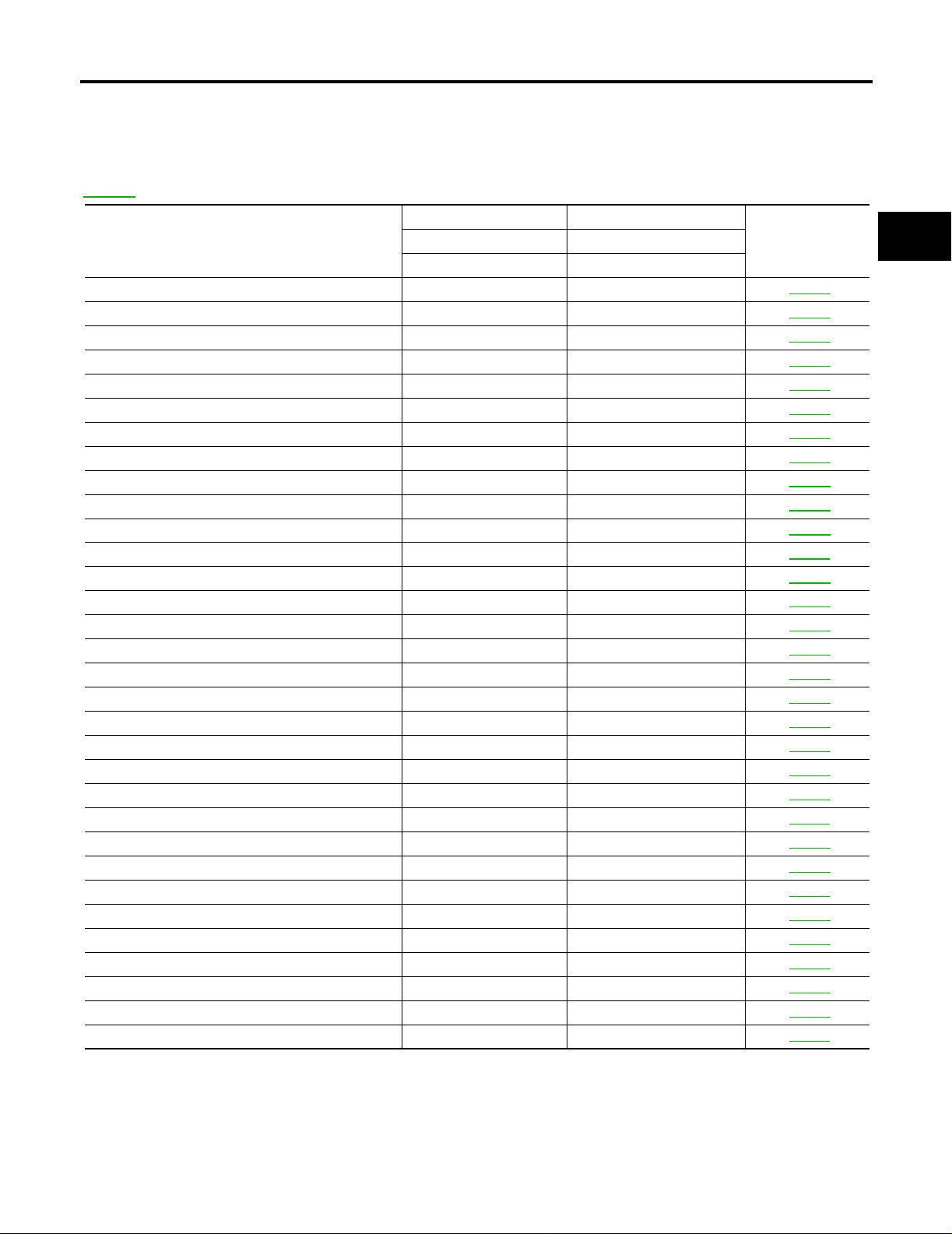
Alphabetical Index
NOTE:
If DTC U1000 is displayed with other DTC, first perform the trouble diagnosis for DTC U1000. Refer to
AT-107
*1: These numbers are prescribed by SAE J2012.
*2: These malfunctions cannot be display ed M IL if anoth er mal fu nct io n is assig ned t o MIL.
.
DTC
Items
(CONSULT-II screen terms)
CONSULT-II GST (*1) CONSULT-II only “A/T”
A/T 1ST E/BRAKING — P1731 AT-145
ATF PRES SW 1/CIRC — P1841 AT-183
ATF PRES SW 3/CIRC — P1843 AT-186
ATF PRES SW 5/CIRC — P1845 AT-189
ATF PRES SW 6/CIRC — P1846 AT-192
A/T INTERLOCK P1730 P1730 AT-142
A/T TCC S/V FNCTN P0744 P0744 AT-124
ATF TEMP SEN/CIRC P0710 P1710 AT-134
CAN COMM CIRCUIT U1000 U1000 AT-107
D/C SOLENOID/CIRC P1762 P1762 AT-160
D/C SOLENOID FNCTN P1764 (*2 ) P1764 AT-163
ENGINE SPEED SIG — P0725 AT-119
FR/B SOLENOID/CIRC P1757 P1757 AT-154
FR/B SOLENOID FNCT P1759 P1759 AT-157
HLR/C SOL/CIRC P1767 P1767 AT-166
HLR/C SOL FNCTN P1769 (*2 ) P1769 AT-169
I/C SOLENOID/CIRC P1752 P1752 AT-148
I/C SOLENOID FNCTN P1754 (*2 ) P1754 AT-151
L/PRESS SOL/CIRC P0745 P0745 AT-127
LC/B SOLENOID/CIRC P1772 P1772 AT-172
LC/B SOLENOID FNCT P1774 P1774 AT-175
MANU MODE SW/CIR — P1815 AT-178
PNP SW/CIRC P0705 P0705 AT-113
STARTER RELAY/CIRC — P0615 AT-109
TCC SOLENOID/CIRC P0740 P0740 AT-121
TCM P0700 P0700 AT-112
TCM·RAM — P1702 AT-130
TCM·ROM — P1703 AT-131
TP SEN/CIRC A/T — P1705 AT-132
TURBINE REV S/CIRC P1716 P1716 AT-137
VEH SPD SE/CIR·MTR — P1721 AT-140
VEH SPD SEN/CIR AT P0720 P0720 AT-116
Reference pageOBD-II Except OBD-II
UCS002ME
A
B
AT
D
E
F
G
H
I
J
K
L
M
Revision: April 2004 2004 Titan
AT-5
Page 6
INDEX FOR DTC
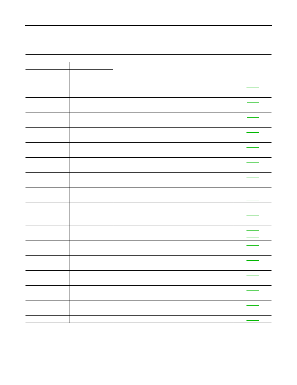
DTC No. Index
UCS002MF
NOTE:
If DTC U1000 is displayed with other DTC, first perform the trouble diagnosis for DTC U1000. Refer to
AT-107
*1: These numbers are prescribed by SAE J2012.
*2: These malfunctions cannot be displayed MIL if another malfunction is assigned to MIL.
.
DTC
OBD-II Except OBD-II
CONSULT-II
GST (*1)
— P0615 STARTER RELAY/CIRC AT-109
P0700 P0700 TCM AT-112
P0705 P0705 PNP SW/CIRC AT-113
P0710 P1710 ATF TEMP SEN/CIRC AT-134
P0720 P0720 VEH SPD SEN/CIR AT AT-116
— P0725 ENGINE SPEED SIG AT-119
P0740 P0740 TCC SOLENOID/CIRC AT-121
P0744 P0744 A/T TCC S/V FNCTN AT-124
P0745 P0745 L/PRESS SOL/CIRC AT-127
— P1702 TCM·RAM AT-130
— P1703 TCM·ROM AT-131
— P1705 TP SEN/CIRC A/T AT-132
P1716 P1716 TURBINE REV S/CIRC AT-137
— P1721 VEH SPD SE/CIR·MTR AT-140
P1730 P1730 A/T INTERLOCK AT-142
— P1731 A/T 1ST E/BRAKING AT-145
P1752 P1752 I/C SOLENOID/CIRC AT-148
P1754 (*2 ) P1754 I/C SOLENOID FNCTN AT-151
P1757 P1757 FR/B SOLENOID/CIRC AT-154
P1759 (*2 ) P1759 FR/B SOLENOID FNCT AT-157
P1762 P1762 D/C SOLENOID/CIRC AT-160
P1764 (*2 ) P1764 D/C SOLENOID FNCTN AT-163
P1767 P1767 HLR/C SOL/CIRC AT-166
P1769 P1769 HLR/C SOL FNCTN AT-169
P1772 P1772 LC/B SOLENOID/CIRC AT-172
P1774 P1774 LC/B SOLENOID FNCT AT-175
— P1815 MANU MODE SW/CIR AT-178
— P1841 ATF PRES SW 1/CIRC AT-183
— P1843 ATF PRES SW 3/CIRC AT-186
— P1845 ATF PRES SW 5/CIRC AT-189
— P1846 ATF PRES SW 6/CIRC AT-192
U1000 U1000 CAN COMM CIRCUIT AT-107
CONSULT -II
only “A/T”
(CONSULT-II screen terms )
Items
Reference page
Revision: April 2004 2004 Titan
AT-6
Page 7

PRECAUTIONS
PRECAUTIONS PFP:00001
Precautions for Supplemental Restraint System (SRS) “ AIR BAG” and “SEAT BELT PRE-TENSIONER”
UCS002MG
A
The Supplemental Re straint System such as “AIR BAG” and “SEAT BELT PRE-TENSIONER”, used along
with a front seat belt, helps to reduce the risk or severity of injury to the driver and front passenger for certain
types of collision. This system includ es seat belt switch inputs and dual stage front air bag modules. The SRS
system uses the seat belt switches to determine the front air bag deployment, and may only deploy one front
air bag, depending on the severity of a collision and whether the front occupants are belted or unbelted.
Information necessary to service the system safely is included in the SRS and SB section of this Service Manual.
WARNING:
● To avoid ren dering the SRS ino perative, w hich could inc rease the ris k of personal injury or death
in the event of a collision which would result in air bag inflation, all maintenance must be performed by an authorized NISSAN/INFINITI dealer.
● Improper maintenance, inc luding incorrect removal and installation of the SRS, can lead to per-
sonal injury ca use d by unintentional ac tiv atio n o f the system. For remo va l of Spiral Cable and Air
Bag Module, see the SRS section.
● Do not use electrical test equ ipment o n any circu it related to the SRS unless in structed to in this
Service Manual. SRS wiring harnesses can be identified by yellow and/or orange harnesses or
harness connectors.
Precautions for On Board Diagnostic (OBD) System of A/T and Engine
UCS002MH
The ECM has an on boa rd diagnos tic system. It wil l light up the m alfunction indicator la mp (MIL) to warn th e
driver of a malfunction causing emission deterioration.
CAUTION:
● Be sure to turn the ignition switch “OFF” and disconnect the negative battery cable before any
repair or inspection work. The open/short circuit of related switches, sensors, solenoid valves,
etc. Will cause the MIL to light up.
● Be sure to connect and lock the connectors securely after work. A loose (unlocked) connector will
cause the MIL to light up due to an open circuit. (Be sure the connector is free from water, grease,
dirt, bent terminals, etc.)
● Be sure to route and secure the harnesses properly after work. Interference of the harness with a
bracket, etc. May cause the MIL to light up due to a short circuit.
● Be sure to connect rubber tubes properly after work. A misconnected or disconnected rubber tube
may cause the MIL to light up due to a malfunction of the EGR system or fuel injection system, etc.
● Be sure to eras e the u nnecess ary mal function i nformatio n (repairs compl eted) from the TC M and
ECM before returning the vehicle to the custom er.
B
AT
D
E
F
G
H
I
J
K
L
Revision: April 2004 2004 Titan
AT-7
M
Page 8
PRECAUTIONS
Precautions
UCS002MI
NOTE:
If any malfu n cti o ns oc cu r i n th e RE 5R 05A m o del t ran s mi ss ion , re pl a ce th e en ti r e transmission assembly.
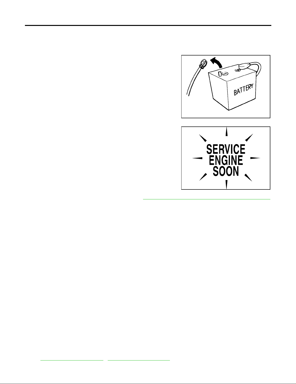
● Before connecting or disconne cting the TCM harness con-
nector, turn ignition switch “OFF” and disconne ct negative
battery cable. Because battery voltage is applied to TCM
even if ignition switch is turned “OFF”.
SEF289H
● After performing each TROUBLE DIAGNOSIS, perform
“DTC (Diagnostic Trouble Code) CONFIRMATION PROCEDURE”.
If the repair is compl eted the DTC should not be display ed in
the “DTC CONFIRMATION PROCEDURE”.
SEF217U
● Always use the specified brand of ATF. Refer to MA-10, "RECOMMENDED FLUIDS AND L UBRICANTS "
.
● Use pap er rags not cloth rags during work.
● After replacing the ATF, dispose of the waste oil using the methods prescribed by law, ordinance, etc.
● Before proceeding with disassembly, thoroughly clean the outside of the transmission. It is important to
prevent the internal parts from becoming contaminated by dirt or other f o reign matter.
● Disassembly should be done in a clean work area.
● Use lint-free cloth or towels for wiping parts clean. Common shop rags can leave fibers that could interfere
with the operation of the trans m is si on .
● Place disassembled parts in order for easier and pro per assembly.
● All parts should be carefully cleaned with a general purpose, non-flammable solvent before inspection or
reassembly.
● Gaskets, seals and O-rings should be replaced any time the transmission is disassembled.
● It is very important to perform functional tests whenever they are indicated.
● The valve bo dy co ntains precision p a rts and requires extre me ca re w h en p ar t s ar e r em ov ed and s er v ic ed .
Place disassembled valve body parts in order for easier and proper assembly. Care will also prevent
springs and small parts from be coming scattered or lost .
● Properly installed valves, sle ev e s, plugs, etc. will slide along bores in valve body unde r thei r own we ig ht.
● Before assembly, apply a coat of recommended ATF to all parts. Apply petroleum jelly to protect O-rings
and seals, or hold bearings and washers in place during assembly. Do not use grease.
● Extreme care should be taken to avoid damage to O-rings, seals and gaskets when assembling.
● After overhaul, refill the transmission with new A TF.
● When the A/T drain plug is remove d, only some of t he fluid is drai ned. O ld A/T flu id wil l remain i n torque
converter and ATF cooling system.
Always follow the procedures under “Changing A/T F luid” i n the AT section when chan ging A/T flu id. Refer
to AT-13, "
Changing A/T Fluid" , AT-13, "Checking A/T Fluid" .
Revision: April 2004 2004 Titan
AT-8
Page 9

PRECAUTIONS
Service Notice or Precautions
UCS002MJ
ATF COOLER SERVICE
● If A/T fluid contains fictional material (clutches, bands, etc.), or if an A/T is repaired, overhauled, or
replaced, inspect and clean the A/T fluid cooler mounted i n the radiator or replace the ra diator. Flush
cooler lines with cleaning solvent and compressed air after repair. For A/T fluid cooler cleaning procedure,
refer to AT-15, "
A/T Fluid Cooler Cleaning" . For radiator replacement, refer to CO-10, "REMOVAL" .
CHECKING AND CHANGING A/T FLUID
● Increase ATF oil temperature to 80°C (176°F) first, then check and adjust oil level at 65°C (149°F).
NOTE:
The A/T has both water cooling a nd air cooling systems. The air cooling system ha s a bypass valve.
When ATF oil temperatur e is at or bel ow 50 °C (122°F), it does not flow through the air cooled system. If A/
T oil level is adjusted without flow throughout the entire system, the level will be 10mm lower than
required. T herefore, all piping should be filled with oil when adjusting level.
OBD-II SELF-DIAGNOSIS
● A/T self-diagnosis is performed by the TCM in combination with the ECM. The results can be read through
the blinking pattern of the A/T CHECK indicator or the malfunction indicator lamp (MIL). Refer to the table
on AT- 9 7, "
result.
● The self-diagnostic results indicated by the MIL are automatically stored in both the ECM and TCM mem-
ories.
Always perform the procedure on AT-43, "
unnecessary blinking of the MIL.
For details of OBD-II, refer to AT-42, "
● Certain systems and componen ts, especially those related to OBD, may use the new s tyle slid e-
locking type harness connector. For description and how to disconnect, refer to PG-69, "
NESS CONNECTOR" .
Wiring Diagrams and Trouble Diagnosis
SELF-DIAGNOSTIC RESULT MODE" for the indicator u sed to display eac h self-diagnostic
HOW TO ERASE DTC" to complete the repair a nd avoid
ON BOARD DIAGNOSTIC (OBD) SYSTEM" .
HAR-
UCS002MK
A
B
AT
D
E
F
G
H
I
When you read wiring diagrams, refer to the following:
● GI-15, "How to Read Wiring Diagrams".
● PG-4, "POWER SUPPLY ROUTING CIRCUIT" for power distribution circuit.
When you perform trouble diagnosis, refer to the following:
● GI-9, "How to Follow Trouble Diagnoses".
● GI-27, "How to Perform Efficient Diagnosis for an Electrical Incident".
J
K
L
M
Revision: April 2004 2004 Titan
AT-9
Page 10
PREPARATION
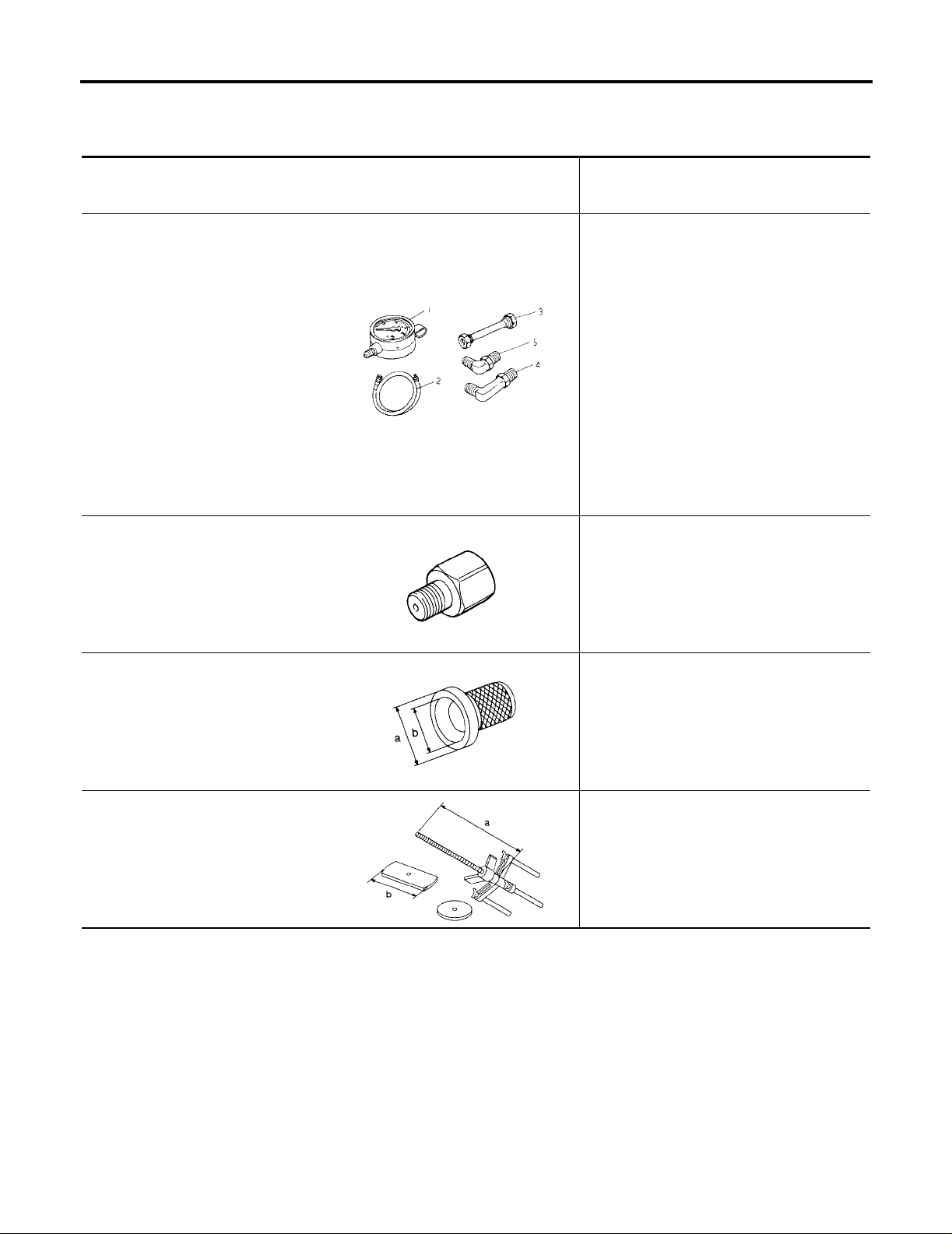
PREPARATION PFP:00002 Special Service Tools
The actual shapes of Kent-Moore tools may differ from those of spe ci al se rvice tools illustrated here.
Tool number
(Kent-Moore No.)
Tool name
ST2505S001
(J-34301-C)
Oil pressure gauge set
1 ST25051001
( — )
Oil pressure gauge
2 ST25052000
( — )
Hose
3 ST25053000
( — )
Joint pi pe
4 ST25054000
( — )
Adapter
5 ST25055000
( — )
Adapter
KV31103600
(J-45674)
Joint pipe adapter
(With ST25054000)
ZZA0600D
Description
Measuring line pressure
Measuring line pressure
UCS002UA
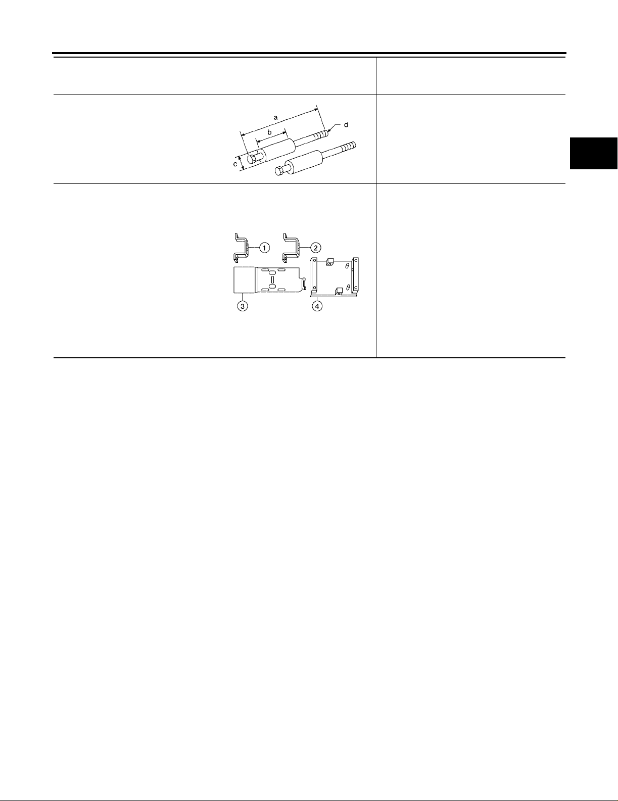
ST33400001
(J-26082)
Drift
a: 60 mm (2.36 in) dia
b: 47 mm (1.85 in) dia
KV31102400
(J-34285 and J-34285-87)
Clutch spring compressor
a: 320 mm (12.60 in)
b: 174 mm (6.85 in)
ZZA1227D
● Installing rear oil seal (2WD models)
● Installing oil pump housing oil seal
NT086
Installing reverse brake return spring retainer
NT423
Revision: April 2004 2004 Titan
AT-10
Page 11
PREPARATION
Tool number
(Kent-Moore No.)
Tool name
ST25850000
(J-25721-A)
Sliding h a mmer
a: 179 mm (7.05 in)
b: 70 mm (2.76 in)
c: 40 mm (1.57 in)
d: M12X1.75P
—
(J-47002)
Transmission jack adapter kit
—
(J-47002-1)
Center bracket (Pathfinder with AllMode 4WD)
—
(J-47002-2)
Center bracket (Titan and Armada)
—
(J-47002-3)
Adapter plate
—
(J-47002-4)
Adapter block
NT422
LCIA0364E
Description
Remove oil pump assembly
Assist in removal of transmission and transfer
case as one assembly using only one transmission jack.
A
B
AT
D
E
F
G
H
K
M
I
J
L
Revision: April 2004 2004 Titan
AT-11
Page 12
PREPARATION
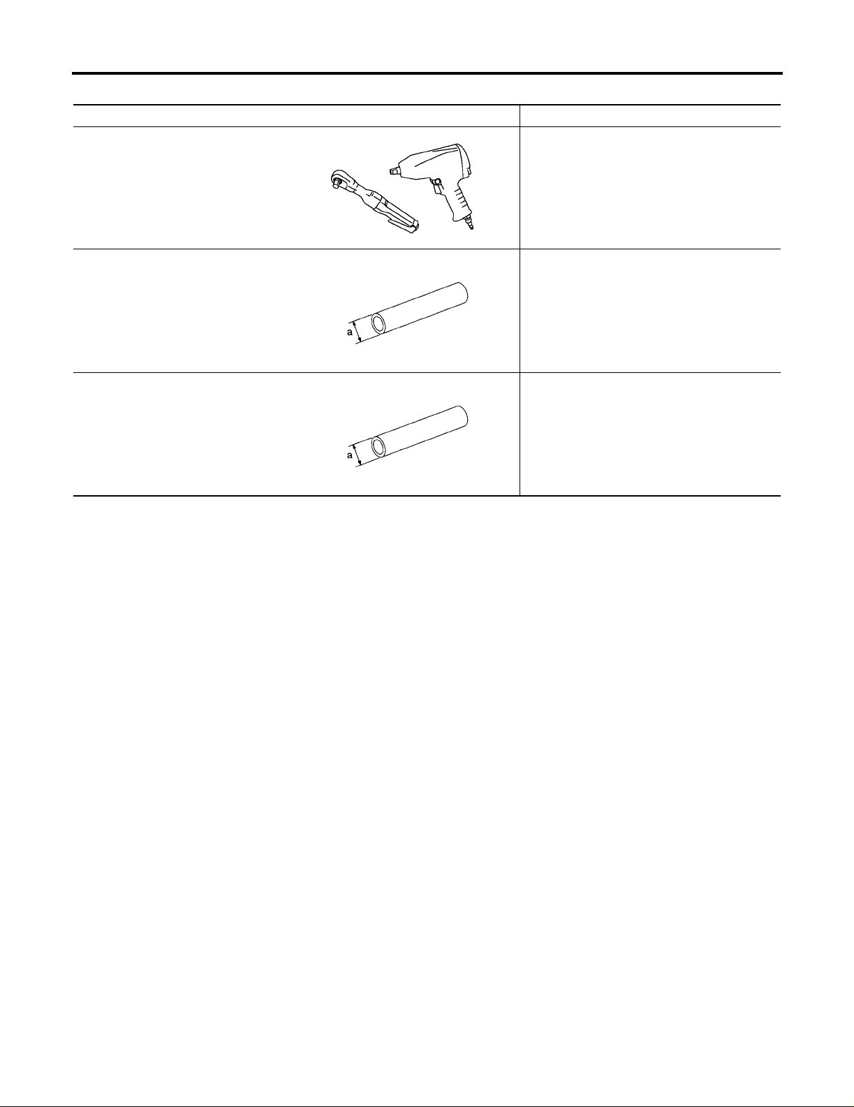
Commercial Service Tools
Tool name Description
Power tool Loosening bolts and nuts
PBIC0190E
Drift
a: 22 mm (0.87 in)
NT083
Drift
a: 64 mm (2.52 in)
NT083
Installing manual shaft seal
Installing rear oil seal (4WD models)
UCS002UB
Revision: April 2004 2004 Titan
AT-12
Page 13

A/T FLUID
A/T FLUID PFP:KLE40
Changing A/T Fluid
1. Increase ATF oil temperature to 80°C (176°F) once.
2. Stop engine.
3. Remove the tightening bolt for ATF level gauge.
4. Drain ATF from drain plug and refill with new ATF. Always refill same volume with drained fluid.
● To replace the ATF, pour in new fluid at the charging pipe with the engine idling and at the same time
drain the old fluid from the radiator cooler hose return side.
● When the color o f the fluid coming out is abo ut th e s a me a s the c ol or of the new fl ui d, the replacement
is complete. The amount of new transmis sion fluid to use should b e 30 to 50% i ncrease of t he stipulated amount .
UCS002MN
A
B
AT
D
ATF: NISSAN Matic Fluid J
Fluid capacity: 10.6 (1 1-1/4 US qt, 9-3/8 lmp qt)
CAUTION:
● Use only Genuine NISSAN ATF Matic Fluid J. Do not mix with other fluid.
● Using automatic transmissi on fluid other than Genuine NISSAN ATF Matic Fluid J will cause
deterioration in driveabi lity and automatic transmission dura bility, and may damage the automatic transmission, which is not covered by the warranty.
● When filling ATF, take care not to splash ATF on heat generating parts such as exhaust.
● Do not reuse drain plug gasket.
Drain plug: : 34 N·m (3.5 kg-m, 25 ft-lb)
5. Increase ATF oil temperature to 80°C (176°F) once.
6. Check fluid leve l and condition . Refer to MA-21, "
Checking A/T Fluid" . If fluid is still dirty, repeat step 2.
through 5.
7. Install the removed ATF level gauge in the fluid charging pipe.
8. Tighten the level gauge bolt.
Level gauge bolt: : 5.1 N·m (0.52 kg-m, 45 in-lb)
Checking A/T Fluid
UCS002MO
1. Wa rm up engine.
2. Check for fluid leakage.
3. Remove the tightening bolt for ATF level gauge.
4. Before driving, fluid level can be checked at fluid temperatures of 30° to 50°C (86° to 122°F) using
“COLD” range on ATF level gauge as follows.
a. Park vehicle on level surface and set parking brake.
b. Start engine and move selector lever through each gear position. Leave selector lever in “P” position.
c. Check fluid level with engine idling.
d. Remove ATF level gauge and wipe clean with lint-free paper.
CAUTION:
When wiping away the fluid level gauge, always use lint-free paper, not a cloth one.
e. Re-inser t ATF leve l gauge into charging pipe as far as it will go.
CAUTION:
To check fluid level, insert the ATF level gauge until the cap contacts the end of the charging pipe,
with the gauge reversed from the normal attachment conditions.
f. Remove ATF level gauge and note reading. If reading is at low side of range, add fluid to th e charging
pipe.
CAUTION:
Do not overfill.
5. Increase ATF oil temperature to 80°C (176°F) once.
E
F
G
H
I
J
K
L
M
Revision: April 2004 2004 Titan
AT-13
Page 14
A/T FLUID
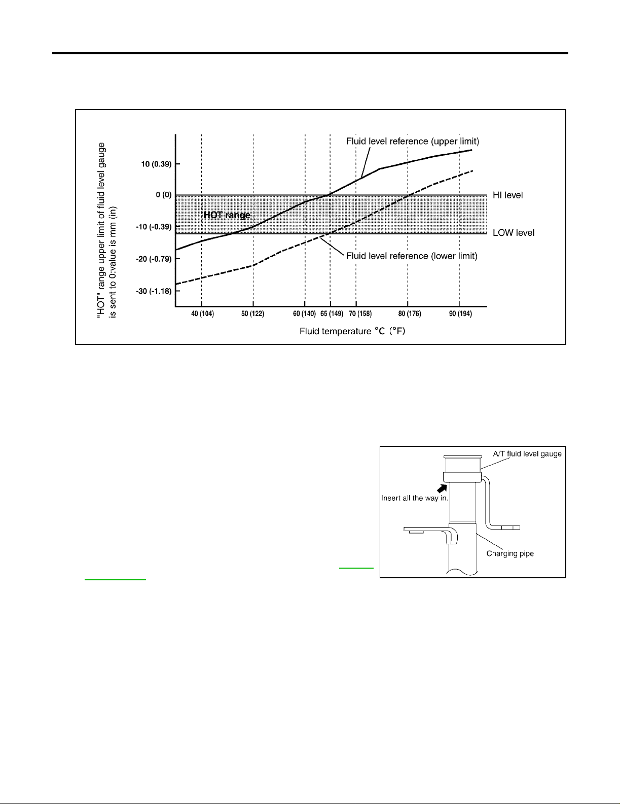
6. Make the fluid temperature approximately 65°C (149°F).
NOTE:
Fluid level will be greatly affected by temperatu re as shown in figure. The refore, be certain to perform operation while checking data with CONSULT-II.
SLIA0016E
a. Connect CONSULT-II to data link connector.
b. Select “MAIN SIGNALS” in “DATA MONITOR ” mode for “A/T” with CONSULT-II.
c. Read ou t the value of “ATF TEMP 1”.
7. Re-check fluid leve l at fluid tempe ratures of app roximately 65 °C (149°F) using “HOT” range on A/T fluid
level gauge.
CAUTION:
● When wiping away the fluid level gauge, always use lint-free paper, not a cloth one.
● To chec k fluid level, insert the ATF level gauge until the
cap contacts the end of the charging pipe, with the gauge
reversed from the normal attachment conditions as
shown.
8. Check fluid condition.
● If fluid is ve ry dark or smells burned, check operation of A/T.
Flush cooling system after repair of A/T.
● If ATF contains frictional material (clutches, bands, etc.),
replace radiat or and flush cooler line using cl eaning solvent
and compressed air after repair of A/T. Refer to CO-10,
"RADIATOR" .
SCIA1684E
9. Install the removed ATF level gauge into the fluid charging pipe.
10. Tighten the level gauge bolt.
Level gauge bolt: : 5.1 N·m (0.52 kg-m, 45 in-lb)
Revision: April 2004 2004 Titan
AT-14
Page 15
A/T FLUID
A/T Fluid Cooler Cleaning
UCS002MP
Whenever an au to ma tic tra ns m is si on is repai red, overhauled, or replaced, the A/T flu id co oler mounted in th e
radiator must be inspected and cleaned.
Metal debris and fri ct ion ma teri al, i f pres ent, can beco me trapp ed i n the A/T fl uid c oole r. This debris ca n co ntaminate the newly serviced A/T or, in severe cases, can block or restrict the flow of A/T fluid. In either case,
malfunction of the newly serviced A/T may result.
Debris, if present, may build up as A/T fluid enters the cooler inlet. It will be necessary to back flush the cooler
through the cooler outlet in order to flush out any built up debris.
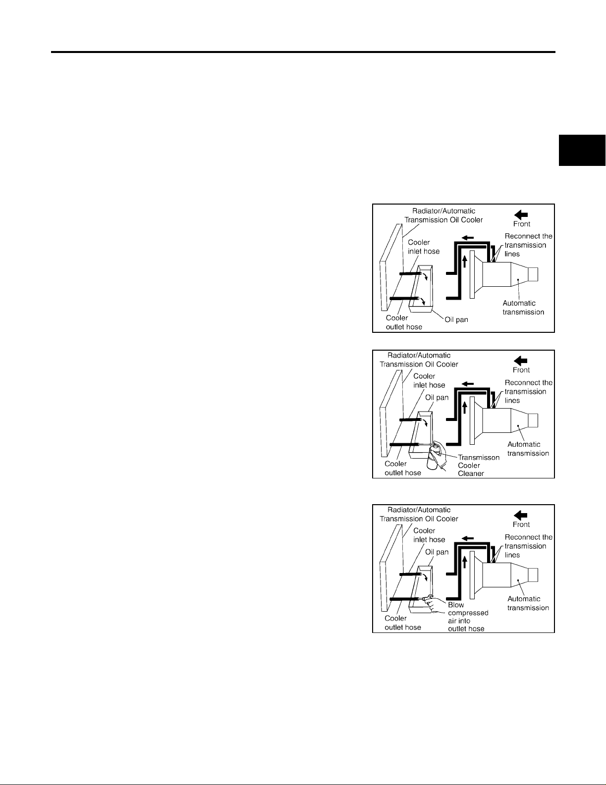
A/T FLUID COOLER CLEANING PROCEDURE
1. Position an oil pan under the aut omatic transmission's inlet and outlet cooler hoses.
2. Identify the inlet and outlet fluid cooler hoses.
3. Disconnect the fluid cooler inlet and outlet rubber hoses from the
steel cooler tubes or bypass valve.
NOTE:
Replace the cooler hoses if rubber material from the hose
remains on the tube fitting.
4. Allow any A/T fluid that remains in the cooler hoses to drain into
the oil pan.
SCIA3830E
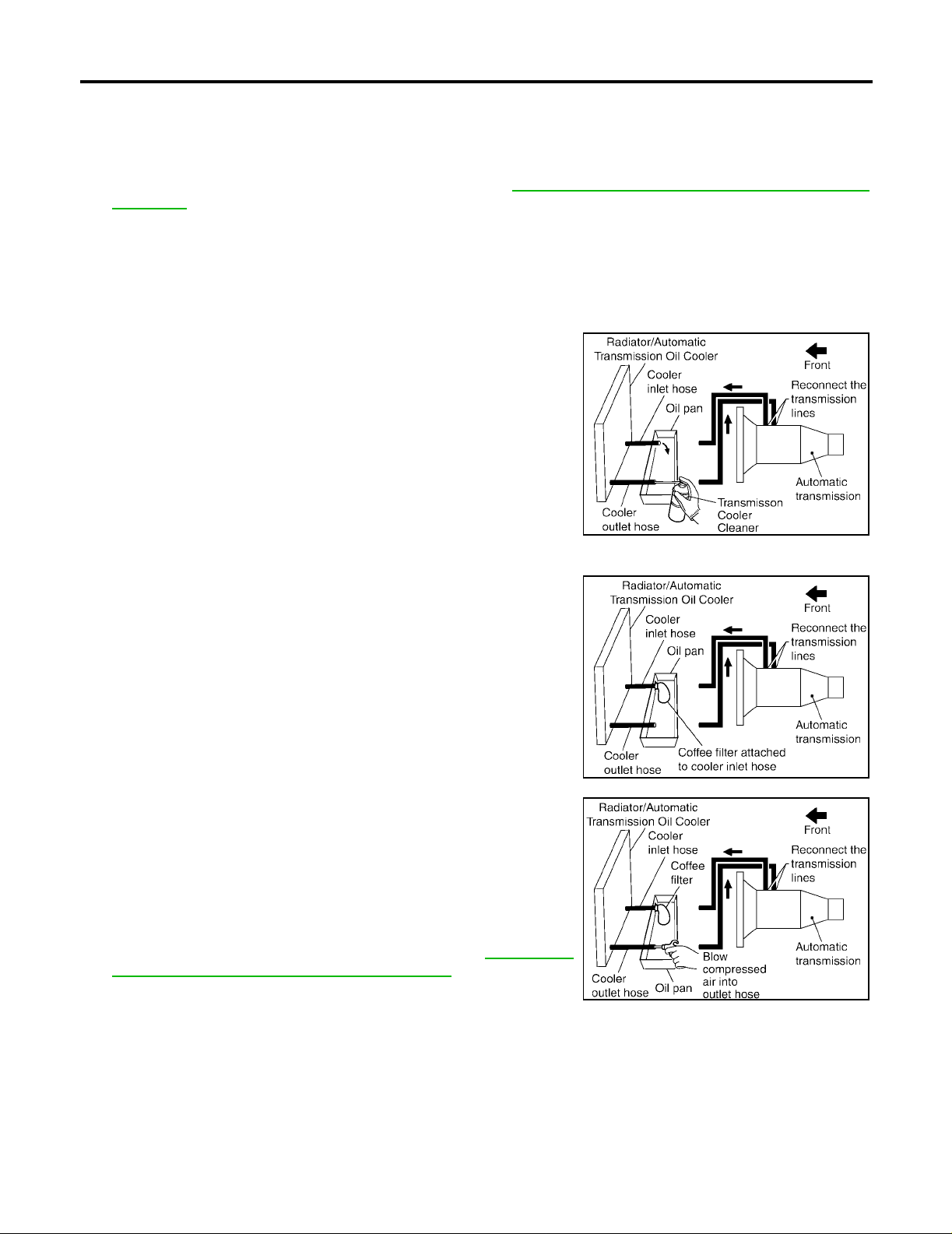
5. Insert the extension adapter hose of a can of Transmission
Cooler Cleaner (Nissan P/N 99 9MP-AM00 6) into the coole r outlet hose.
CAUTION:
● Wear safety glasses and rubber gloves when spraying
the Transmission Cooler Cleaner .
● Spray cooler cleaner only with ad equ ate venti lation.
● Avoid contact with eyes and skin.
● Do not breat h vapors or spray mis t.
6. Hold the hose and can as high as possible and spray Transmission Cooler Cleaner in a continuous stream into the cooler outlet
hose until fluid flows out of the cooler inlet hose for 5 seconds.
7. Insert the tip of an air gun into the end of the cooler outle t hose.
8. Wrap a shop rag a round the ai r gun tip and of the cool er outlet
hose.
SCIA3831E
A
B
AT
D
E
F
G
H
I
J
K
L
M
SCIA3832E
9. Blow compressed air regulated to 5 - 9 kg/cm
2
(70 - 130 psi) th rough th e cooler outlet hose fo r 10 sec-
onds to force out any remaining fluid.
10. Repeat steps 5 through 9 three additional times.
11. Position an oil pan under the banjo bolts that connect the fluid cooler steel lines to the transmission.
12. Remove the banjo bolts.
13. Flush each steel li ne fr om th e coo ler sid e bac k towa rd th e transm issi on by sp rayin g Transmissio n Cool er
Cleaner in a continuous stream for 5 seconds.
Revision: April 2004 2004 Titan
AT-15
Page 16
A/T FLUID
14. Blow compre ssed air regulated to 5 - 9 kg/cm2 (70 - 130 psi) through each steel line from the cooler side
back toward the transmission for 10 seconds to force out any re maining fluid.
15. Ensure all debris is removed from the steel cooler lines.
16. Ensure all debris is removed from the banjo bolts and fittings.
17. Perform A/T fliud cooler inspection procedure. Refer to AT-17, "
CEDURE" .
A/T FLUID COOLER DIAGNOSIS PROCEDURE
NOTE:
Insufficient cleaning of the cooler inlet hose exterior may lead to inaccurate debris identification.
1. Position an oil pan under the automatic transmission's inlet and outlet cooler hoses.
2. Clean the exterior and tip of the cooler inlet hose.
3. Insert the extension adapter hose of a can of Transmission
Cooler Cleaner (Nissa n P/N 999M P-AM0 06) into the co oler ou tlet hose.
CAUTION:
● Wear safety glasses and rubber gloves when spraying
the Transmission Cooler Cleaner.
● Spray cooler cleaner only with adequate ventilation.
● Avoid contact with eyes and skin.
● Do not breath vapors or spray mist.
4. Hold the hose and can as high as possible and spray Transmission Cooler Cleaner in a continuous stream into the cooler outlet
hose until fluid flows out of the cooler inlet hose for 5 seconds.
5. Tie a common white, basket-type coffee filter to the end of the
cooler inlet hose.
A/T FLUID COOLER INSPECTION PRO-
SCIA3831E
SCIA3833E
6. Insert the tip of an air gun into the end of the cooler outl et hose.
7. Wrap a shop rag around the air gun tip an d end of cooler ou tlet
hose.
2
8. Blow compressed air regulated to 5 - 9 kg/cm
(70 - 130 psi)
through the cooler outlet hose to force any remaining A/T fluid
into the coffee filter.
9. Remove the coffee filter from the end of the cooler inlet hose.
10. Perform A/T fliud cooler inspection procedure. AT-17, "
A/T
FLUID COOLER INSPECTION PROCEDURE" .
SCIA3834E
Revision: April 2004 2004 Titan
AT-16
Page 17
A/T FLUID
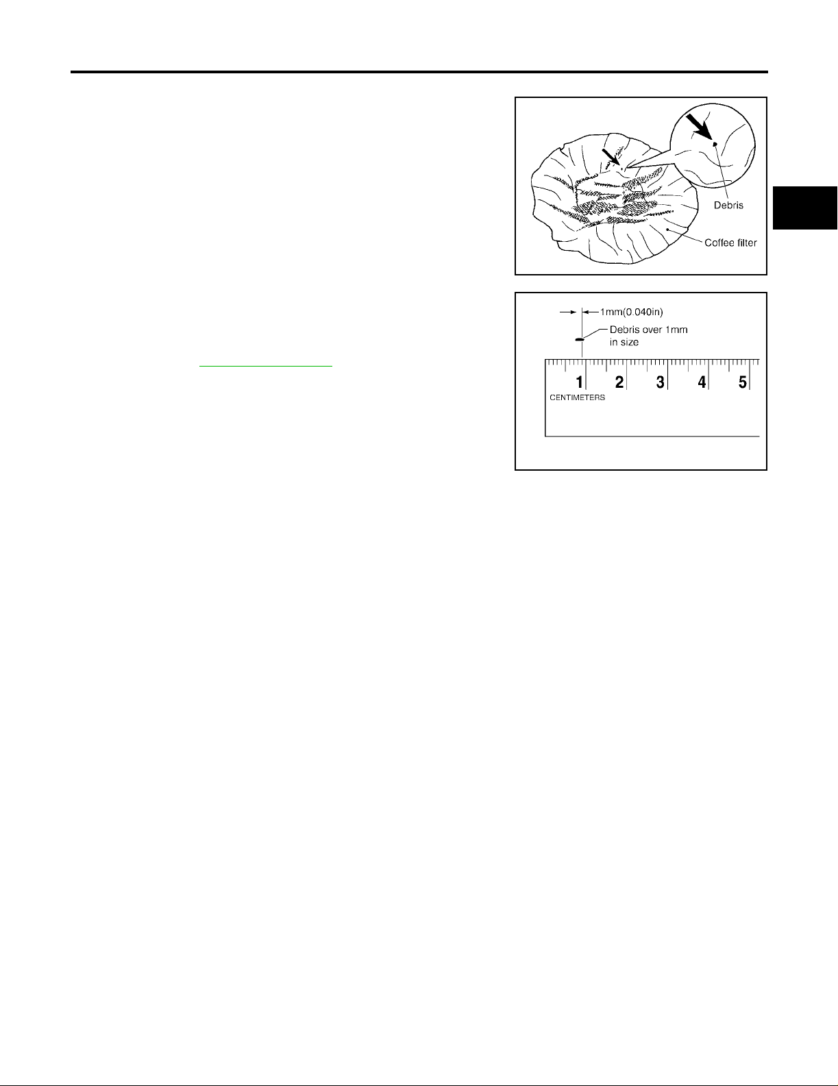
A/T FLUID COOLER INSPECTION PROCEDURE
1. Inspect the coffee filter for debris.
a. If small metal debri s less than 1mm (0.040 in) in size or metal
powder is found in the coffee filter, this is normal. If normal
debris is found, the A/T fluid cooler/radiator can be re-used and
the procedur e is ended.
A
B
AT
b. If one or more pieces of debris are found that are over 1mm
(0.040 in) in siz e an d/or peeled clutch facing material is fo un d in
the coffee filter, the fluid cooler is not servicea ble. The A/T fluid
cooler/radiator must be replaced and the inspection procedure is
ended.Refer to CO-10, "
RADIATOR" .
A/T FLUID COOLER FINAL INSPECTION
After performing all procedures, ensure that all remaining oi l is cleaned from all components.
SCIA2967E
SCIA5257E
D
E
F
G
H
I
J
K
Revision: April 2004 2004 Titan
AT-17
L
M
Page 18
A/T CONTROL SYSTEM
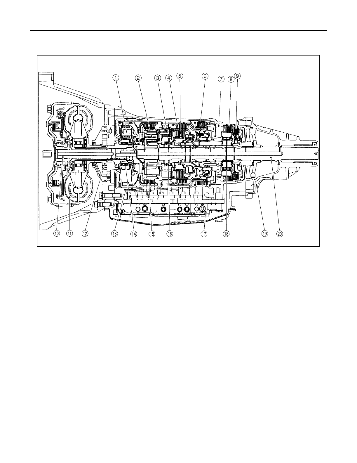
A/T CONTROL SYSTEM PFP:31036 Cross-Sectional View (2WD models)
UCS002MQ
1. Front planetary gear 2. Mid planetary gear 3. Rear planetary gear
4. Direct clutch 5. High & low reverse clutch 6. Reverse brake
7. Drum support 8. Forward brake 9. Low coast brake
10. Input shaft 11. Torque converter 12. Oil pump
13. Front brake 14 . 3rd one-way clut ch 15. Input clutch
16. 1st one-way clutch 17. Control valve with TCM 18. Forward one-way clutch
19. Rear extension 20. Output shaft
SCIA5267E
Revision: April 2004 2004 Titan
AT-18
Page 19
A/T CONTROL SYSTEM
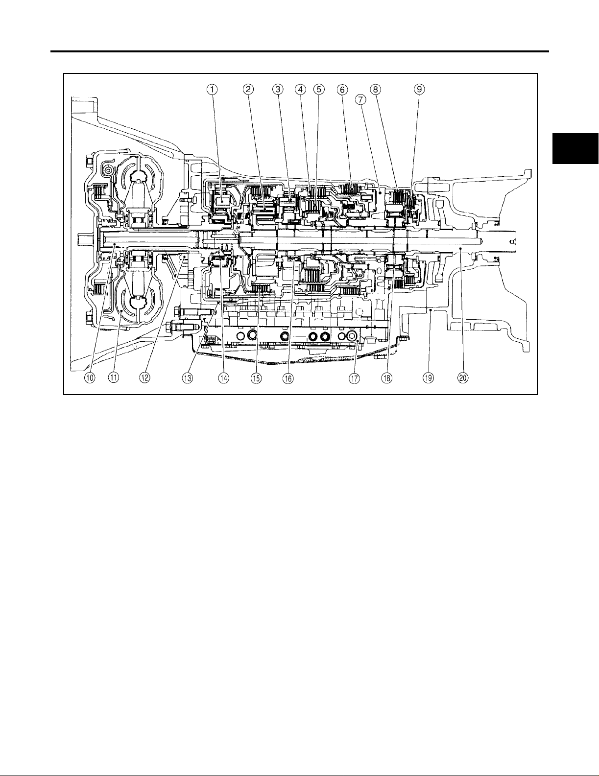
Cross-Sectional View (4WD models)
UCS002MR
A
B
AT
D
E
F
G
H
1. Front planetary gear 2. Mid planetary gear 3. Rear planetary gear
4. Direct clutch 5. High & low reverse clutch 6. Reverse brake
7. Drum support 8. Forward brake 9. Low coast brake
10. Input shaft 11. Torque converter 12. Oil pump
13. Front brake 14. 3rd one-way clutch 15. Input clutch
16. 1st one-way clutch 17. Control valve with TCM 18. Forward one-way clutch
19. Adapter case 20. Output shaft
SCIA5268E
I
J
K
L
M
Revision: April 2004 2004 Titan
AT-19
Page 20

A/T CONTROL SYSTEM
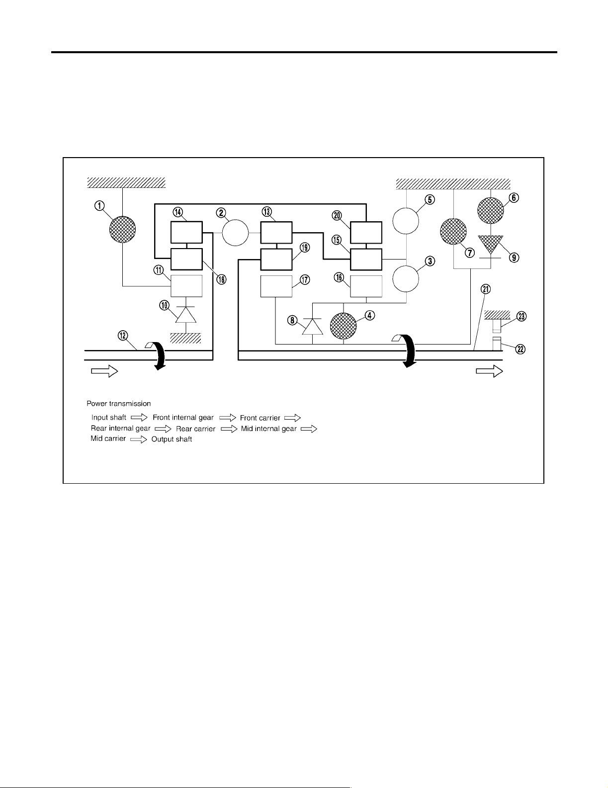
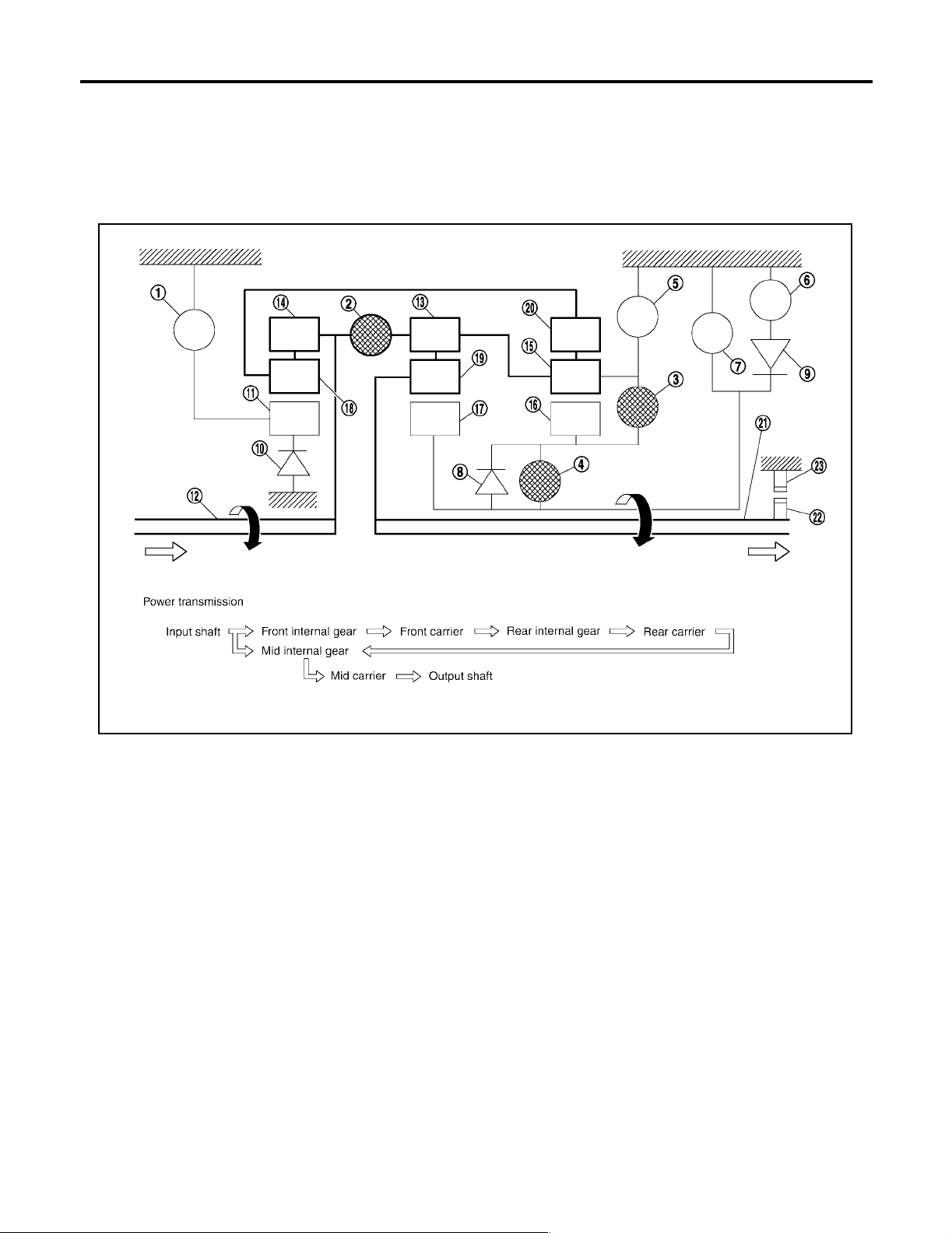
Shift Mechanism
UCS002MS
The automatic tra nsmission uses compact dual plan etary gear systems to improve powe r-transmission efficiency, simplify construction and reduce weight.
It also empl oys an o ptimum shi ft control and supe r wide ge ar ratios. They imp rove starti ng perform ance and
acceleration during medium and high-speed operation.
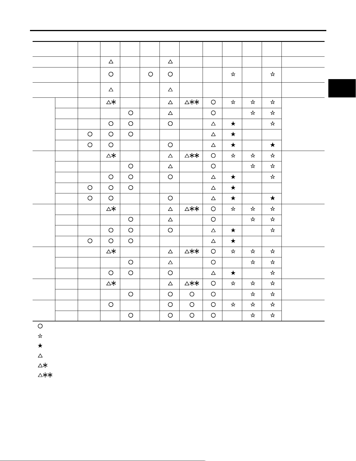
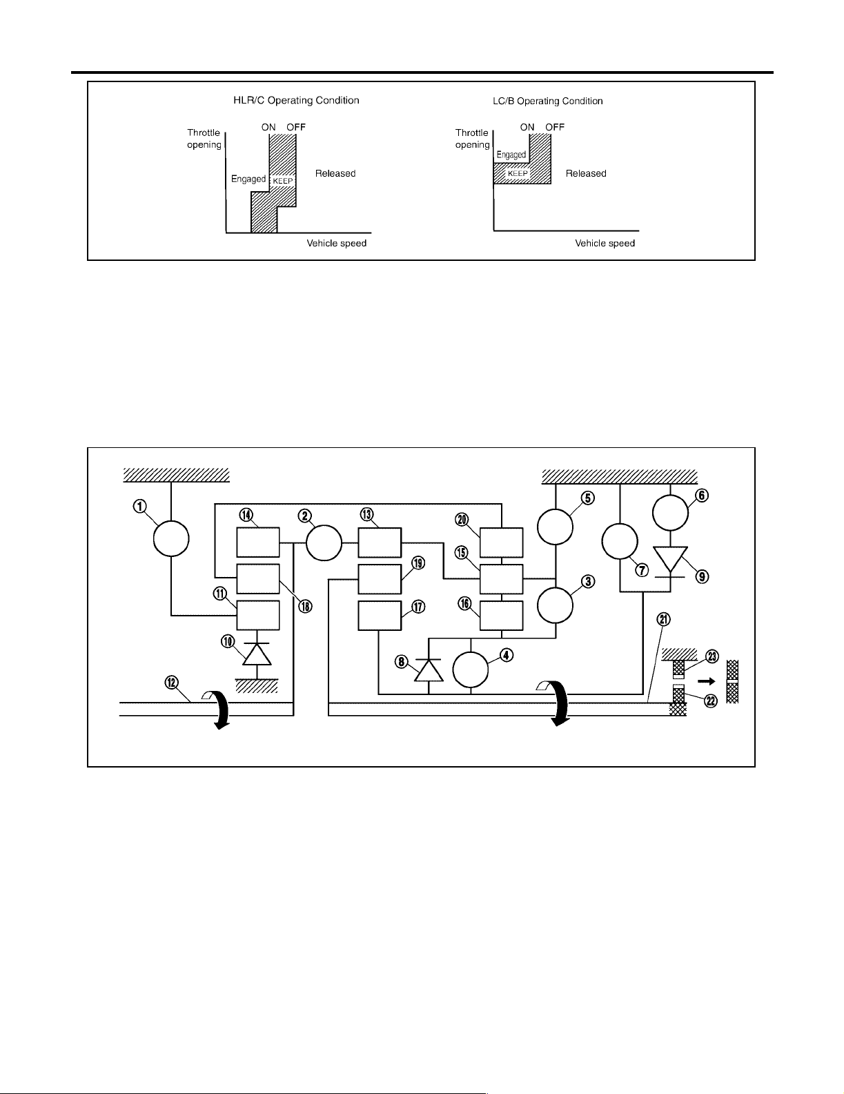
CONSTRUCTION
1. Front brake 2. Input clutch 3. Direct clutch
4. High and low reverse clutch 5. Reverse brake 6. Forward brake
7. Low coast brake 8. 1st one-way clutch 9. Forward one-way clutch
10. 3rd one-way clutch 11. Front sun gear 12. Input sha ft
13. Mid internal gear 14. Front internal gear 15. Rear carrier
16. Rear sun gear 17. Mid sun gear 18. Front car rier
19. Mid carrier 20. Rear internal gear 21. Outpu t sha ft
22. Parking gear 23. Parking pawl
FUNCTION OF CLUTCH AND BRAKE
Name of the Part Abbreviati on Function
Front brake (1) FR/B Fastens t he front sun gear (11).
Input clutch (2) I/C
Direct clutch (3) D/C Connects the rear carrier (15) and the rear sun gear (16).
High and low reverse clutch (4) HLR/C Connects the mid sun gear (17) and the rear sun gear (16).
Reverse brake (5) R/B Fastens the rear carrier (15).
Forward brake (6) F/B Fastens the mid sun gear (17).
Low coast brake (7) LC/B Fastens the mid sun gear (17).
1st one-way clutch (8) 1st/O.C
Forward one-way clutch (9) F/O.C
3rd one-way clutch (10) 3rd/O.C
Connects the input shaft (12), the front internal gear (14) and the mid internal
gear (13).
Allows the rear sun gear (16) to turn freely forward relative to the mid sun gear
(17) but fastens it for reverse rotation.
Allows the mid sun gear (17) to turn freely in the forward direction but fastens it
for reverse rotat i o n.
Allows the front sun gear (11) to turn freely in the forward direction but fastens
it for reverse rotat ion.
PCIA0002J
Revision: April 2004 2004 Titan
AT-20
Page 21

A/T CONTROL SYSTEM
CLUTCH AND BAND CHART (FLOOR SHIFT MODELS)
Shift position I/C HLR/C D/C R/B FR/B LC/B Fwd/B
P PARK POSITION
R
N
1st
2nd
D
3rd
4th
5th
1st
OWC
Fwd
OWC
3rd
OWC
Remarks
REVERSE
POSITION
NEUTRAL POSI-
TION
Automatic shift
1⇔2⇔3⇔4⇔5
A
B
AT
D
E
1st
4
2nd
3rd
4th
1st
2nd
3
3rd
4th
1st
2nd
2
3rd
4th
1st
2nd
1
3rd
4th
● —Operates
● —Operates during “progressive” accel era tion.
● —Operates and effects power transmission while coasting.
● —Line pressure is applied but does not affect power transmiss io n.
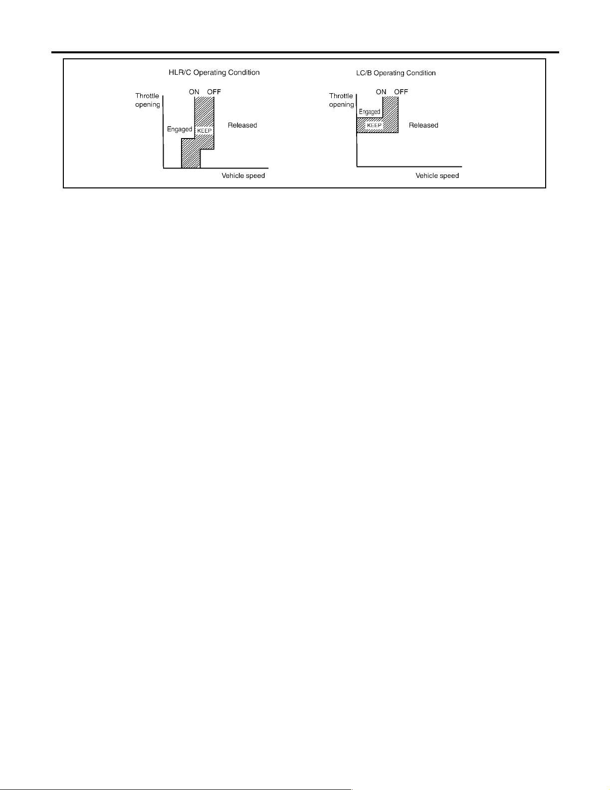
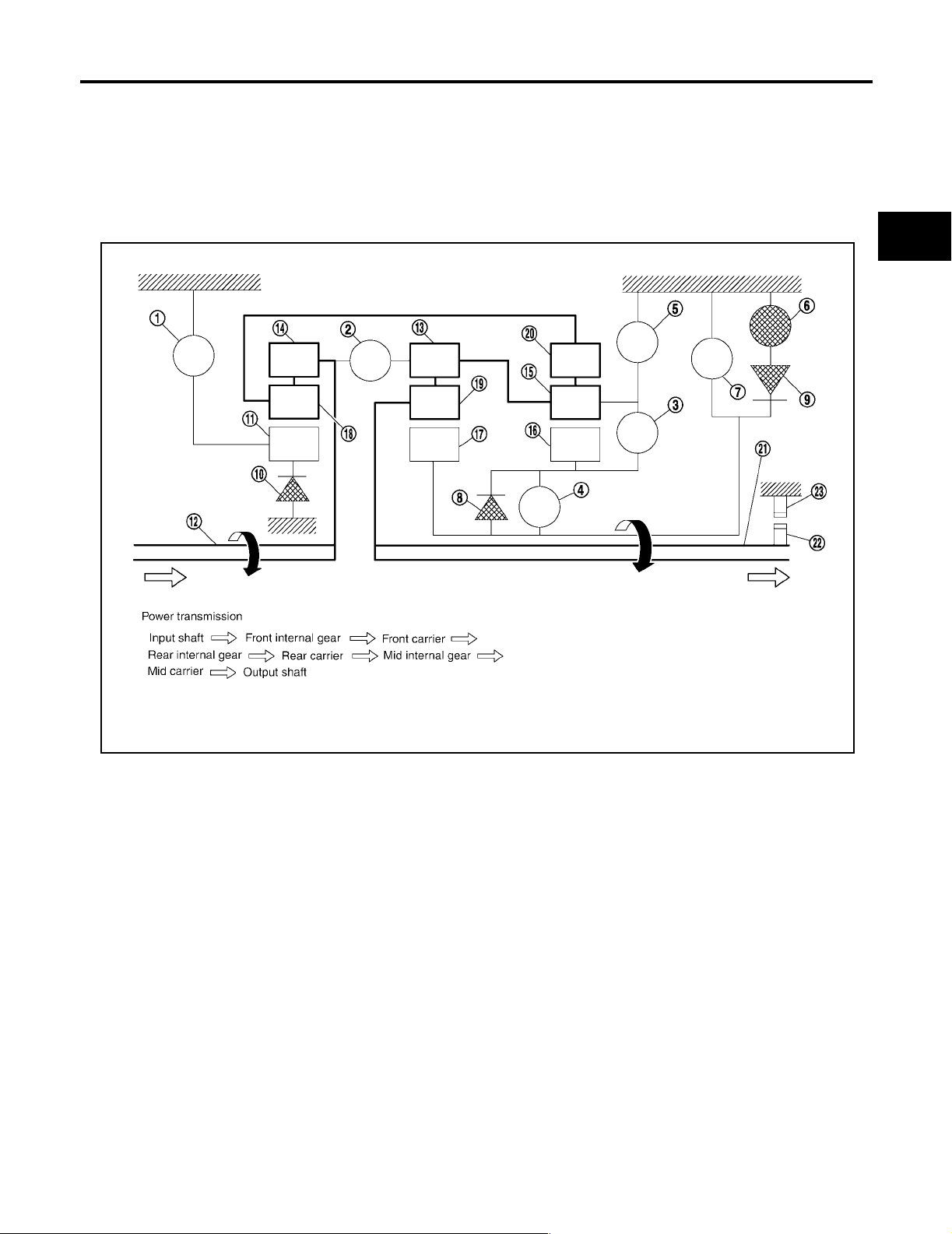
● —Operates under conditions shown in HLR/C Op era ting C ond iti on
● —Operates under conditions show n in LC/B Op era ting Condition. Delay control is applied during D (4,3,2,1) ÞN shift.
Automatic shift
1⇔2⇔3⇔4
Automatic shift
1⇔2⇔3⇐4
Automatic shift
1⇔2⇐3⇐4
Locks (held sta-
tionary in 1st
gear)
1⇐2⇐3⇐4
F
G
H
I
J
K
L
M
Revision: April 2004 2004 Titan
AT-21
Page 22
A/T CONTROL SYSTEM
SCIA5642E
Revision: April 2004 2004 Titan
AT-22
Page 23
A/T CONTROL SYSTEM
CLUTCH AND BAND CHART (COLUMN SHIFT MODELS)
Shift position I/C HLR/C D/C R/B FR/B LC/B Fwd/B
P PARK POSITION
R
N
1st
2nd
D
3rd
4th
5th
1st
OWC
Fwd
OWC
3rd
OWC
Remarks
REVERSE
POSITION
NEUTRAL POSI-
TION
Automatic shift
1⇔2⇔3⇔4⇔5
A
B
AT
D
E
1st
2nd
M5
M4
M3
M2
M1
● —Operates
● —Operates during “progressive” accel era tion.
● —Operates and effects power transmission while coasting.
● —Line pressure is applied but does not affect power transmiss io n.
● —Operates under conditions shown in HLR/C Op era ting C ond iti on
● —Operates under conditions show n in LC/B Op era ting Condition. Delay control is applied during D (4,3,2,1) ÞN shift.
3rd
4th
5th
1st
2nd
3rd
4th
1st
2nd
3rd
1st
2nd
1st
2nd
Automatic shift
1⇔2⇔3⇔4⇔5
Automatic shift
1⇔2⇔3⇔4
Automatic shift
1⇔2⇔3
Automatic shift
1⇔2
Locks (held sta-
tionary in 1st
gear)
F
G
H
I
J
K
L
M
Revision: April 2004 2004 Titan
AT-23
Page 24
A/T CONTROL SYSTEM
SCIA5642E
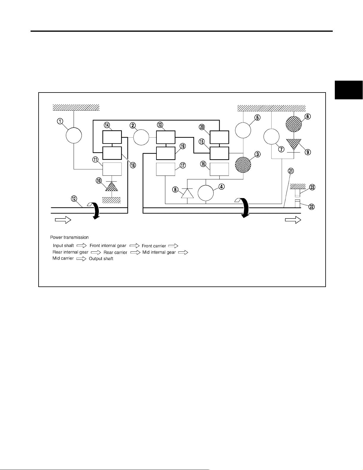
POWER TRANSMISSION
“N” position
Since both the forward brake and the reverse brake are released, torque from the input shaft drive is not transmitted to the output shaft.
“P” position
● The same as for the “N” position, both the forward brake and the reverse brake are released, so torque
from the input shaft drive is not transmitted to the output shaft.
● The parking pawl linked w ith the se lect lever mes hes with the parking gear a nd fastens the output sh aft
mechanically.
PCIA0003J
1. Fr ont brak e 2. I nput clutch 3. Direct clutch
4. H i gh and l ow reverse clutch 5. R everse brake 6. Forward brake
7. Low coast brake 8. 1st one-way clutch 9. Forward one-way clutch
10. 3rd one-way clutch 11. Front sun gear 12. Input shaft
13. Mid internal gear 14. Front internal gear 15. Rear carrier
16. Rear sun gear 17. Mid sun gear 18. Front carrie r
19. Mid carrier 20. Rear internal gea r 2 1. Output shaft
22. Parking gear 23. Parking pawl
Revision: April 2004 2004 Titan
AT-24
Page 25
A/T CONTROL SYSTEM
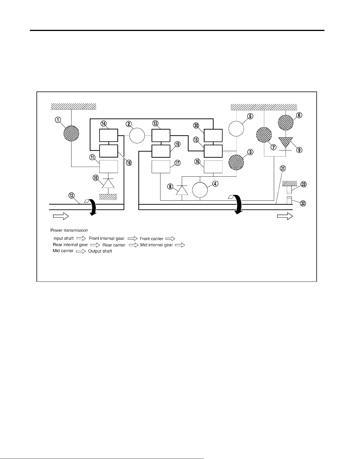
“D”, “M5”, “M4”, “M3”, “M2” positions (column sh ift), “D”, “4”, “3”, “2” positions (floor shift)
1st gear
● The forward brake and the forward one-way clutch regulate reverse rotation of the mid sun gear.
● The 1st one-way clutch regulates reverse rotation of the rear sun gear.
● The 3rd one-way clutch regulates rever s e rotation of the front sun gear .
● During deceleration, the mid sun gear turns forward, so the forward one-way clutch idles and the engine
brake is not act ivated.
A
B
AT
D
E
F
G
1. Front brake 2. Input clutch 3. Dir ect clutch
4. High and low reverse clutch 5. Reverse brake 6. Forward brake
7. Low coast brake 8. 1st one-way clutch 9. Forward one-way clutch
10. 3rd one-way clutch 11. Front sun gear 12. Input shaft
13. Mid internal gear 14. Front internal gear 15. Rear carrier
16. Rear sun gear 17. Mid sun gear 18. F ron t carrier
19. Mid carrier 20. Rear internal gear 21. Output shaft
22. Parking gear 23. Parking pawl
H
I
J
K
SCIA1512E
L
M
Revision: April 2004 2004 Titan
AT-25
Page 26
A/T CONTROL SYSTEM
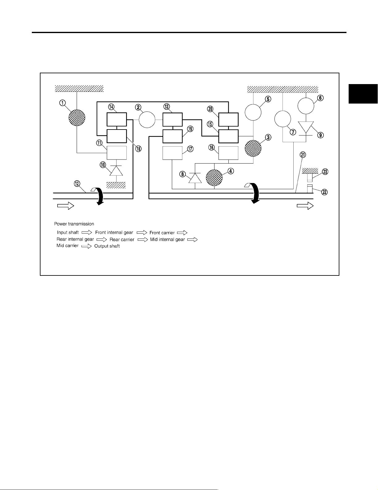
“M1” position (column shift), “1 ” position (floor shift) 1st gear
● The front brake fastens the front sun gear.
● The forward brake and the forward one-way clutch regulate reverse rotation of the mid sun gear.
● High and low reverse clutch connects the rear sun gear and the mid sun gear.
● The low coast brake fastens the mid sun gear.
● During deceleration, the low coast brake regulates forward rotation of the mid sun gear and the engine
brake functions.
1. Fr ont brak e 2. I nput clutch 3. Direct clutch
4. H i gh and l ow reverse clutch 5. R everse brake 6. Forward brake
7. Low coast brake 8. 1st one-way clutch 9. Forward one-way clutch
10. 3rd one-way clutch 11. Front sun gear 12. Input shaft
13. Mid internal gear 14. Front internal gear 15. Rear carrier
16. Rear sun gear 17. Mid sun gear 18. Front carrie r
19. Mid carrier 20. Rear internal gea r 2 1. Output shaft
22. Parking gear 23. Parking pawl
SCIA1513E
Revision: April 2004 2004 Titan
AT-26
Page 27
A/T CONTROL SYSTEM
“D”, “M5”, “M4”, “M3” positions (column shift), “D”, “4”, “3” positions (column shift) 2nd gear
● The forward brake and the forward one-way clutch regulate reverse rotation of the mid sun gear.
● The 3rd one-way clutch regulates rever s e rotation of the front sun gear .
● The direct clutch is coupled and the rear carrier and rear sun gear are connected.
● During deceleration, the mid sun gear turns forward, so the forward one-way clutch idles and engine
brake is not act ivated.
A
B
AT
D
E
F
G
1. Front brake 2. Input clutch 3. Dir ect clutch
4. High and low reverse clutch 5. Reverse brake 6. Forward brake
7. Low coast brake 8. 1st one-way clutch 9. Forward one-way clutch
10. 3rd one-way clutch 11. Front sun gear 12. Input shaft
13. Mid internal gear 14. Front internal gear 15. Rear carrier
16. Rear sun gear 17. Mid sun gear 18. F ron t carrier
19. Mid carrier 20. Rear internal gear 21. Output shaft
22. Parking gear 23. Parking pawl
H
I
J
K
SCIA1514E
L
M
Revision: April 2004 2004 Titan
AT-27
Page 28
A/T CONTROL SYSTEM
“M2”, “M1” positions (column shift), “2”, “1” positions (floor shift) 2nd gear
● The front brake fastens the front sun gear.
● The forward brake and the forward one-way clutch regulate reverse rotation of the mid sun gear.
● The direct clutch is coupled, and the rear carrier and rear sun gear are connected.
● The low coast brake fastens the mid sun gear.
● During deceleration, the low coast brake regulates forward rotation of the mid sun gear and the engine
brake functions.
1. Fr ont brak e 2. I nput clutch 3. Direct clutch
4. H i gh and l ow reverse clutch 5. R everse brake 6. Forward brake
7. Low coast brake 8. 1st one-way clutch 9. Forward one-way clutch
10. 3rd one-way clutch 11. Front sun gear 12. Input shaft
13. Mid internal gear 14. Front internal gear 15. Rear carrier
16. Rear sun gear 17. Mid sun gear 18. Front carrie r
19. Mid carrier 20. Rear internal gea r 2 1. Output shaft
22. Parking gear 23. Parking pawl
SCIA1515E
Revision: April 2004 2004 Titan
AT-28
Page 29
A/T CONTROL SYSTEM
“D”, “M5”, “M4”, “M3” positions (column shift), “D”, “4”, “3” positions (floor shift) 3rd gear
● The front brake fastens the front sun ge ar.
● The direct clutch is coupled, and the rear carrier and rear sun gear are connected.
● The high and low reverse clutch is coupled and the mid sun gear and rear sun gear are connected.
A
B
AT
D
E
F
G
1. Front brake 2. Input clutch 3. Dir ect clutch
4. High and low reverse clutch 5. Reverse brake 6. Forward brake
7. Low coast brake 8. 1st one-way clutch 9. Forward one-way clutch
10. 3rd one-way clutch 11. Front sun gear 12. Input shaft
13. Mid internal gear 14. Front internal gear 15. Rear carrier
16. Rear sun gear 17. Mid sun gear 18. F ron t carrier
19. Mid carrier 20. Rear internal gear 21. Output shaft
22. Parking gear 23. Parking pawl
H
I
J
SCIA1516E
K
L
M
Revision: April 2004 2004 Titan
AT-29
Page 30
A/T CONTROL SYSTEM
“D”, “M5”, “M4” positions (column shift), “D”, “4” positions (floor shift) 4th gear
● The direct clutch is coupled, and the rear carrier and rear sun gear are connected.
● The high an d low reverse clutch is coupled and the mid sun gear and rear sun gear are connected.
● The input clutch is coupled and the front internal gear and mid internal gear are connected.
● The drive power is co nveyed to the front in ternal gear, mid internal gear, and rear carrier an d the three
planetary gears rotate forward as one unit.
1. Fr ont brak e 2. I nput clutch 3. Direct clutch
4. H i gh and l ow reverse clutch 5. R everse brake 6. Forward brake
7. Low coast brake 8. 1st one-way clutch 9. Forward one-way clutch
10. 3rd one-way clutch 11. Front sun gear 12. Input shaft
13. Mid internal gear 14. Front internal gear 15. Rear carrier
16. Rear sun gear 17. Mid sun gear 18. Front carrie r
19. Mid carrier 20. Rear internal gea r 2 1. Output shaft
22. Parking gear 23. Parking pawl
SCIA1517E
Revision: April 2004 2004 Titan
AT-30
Page 31

A/T CONTROL SYSTEM
“D”, “M5” positions (column shift), “D” position (floor shift) 5th gear
● The front brake fastens the front sun ge ar.
● The input clutch is coupled and the front internal gear and mid internal gear are connected.
● The high and low reverse clutch is coupled and the mid sun gear and rear sun gear are connected.
A
B
AT
D
E
F
G
1. Front brake 2. Input clutch 3. Dir ect clutch
4. High and low reverse clutch 5. Reverse brake 6. Forward brake
7. Low coast brake 8. 1st one-way clutch 9. Forward one-way clutch
10. 3rd one-way clutch 11. Front sun gear 12. Input shaft
13. Mid internal gear 14. Front internal gear 15. Rear carrier
16. Rear sun gear 17. Mid sun gear 18. F ron t carrier
19. Mid carrier 20. Rear internal gear 21. Output shaft
22. Parking gear 23. Parking pawl
H
I
J
SCIA4984E
K
L
M
Revision: April 2004 2004 Titan
AT-31
Page 32

A/T CONTROL SYSTEM
“R” position
● The front brake fastens the front sun gear.
● The high and low reverse clutch is coupled, and the mid sun gear and rear sun gear are connected.
● The reverse brake fastens the rear carrier.
1. Fr ont brak e 2. I nput clutch 3. Direct clutch
4. H i gh and l ow reverse clutch 5. R everse brake 6. Forward brake
7. Low coast brake 8. 1st one-way clutch 9. Forward one-way clutch
10. 3rd one-way clutch 11. Front sun gear 12. Input shaft
13. Mid internal gear 14. Front internal gear 15. Rear carrier
16. Rear sun gear 17. Mid sun gear 18. Front carrie r
19. Mid carrier 20. Rear internal gea r 2 1. Output shaft
22. Parking gear 23. Parking pawl
SCIA1519E
Revision: April 2004 2004 Titan
AT-32
Page 33

A/T CONTROL SYSTEM
TCM Function
UCS002MT
The function of the TCM is to:
● Receive input signals sent from various switches and sensors.
● Determine required line pressure, shifting point, lock-up operation, and engine brake operation.
● Send required output signals to the respective solenoids.
CONTROL SYSTEM OUTLIN E ( FLOOR SHIFT)
The automatic transmission se ns es v eh ic le op era ting conditions thro ugh various sens o r s o r s ig nals. It always
controls the optimum shift position and reduces shifting and lock-up shocks.
SENSORS (or SIGNALS)
PNP switch
Accelerator pedal position sensor
Closed throttle position signal
Wide open throttle position signal
Engine speed signal
A/T fluid temperature sensor
Revolution sensor
Vehicle speed signal
Stop lamp switch signal
Turbine revolution sensor
1st position switch signal
4th position switch signal
ATF pressure switch
Tow mode switch signal
Þ
Shift control
Line pressure control
Lock-up control
Engine brake control
Timing control
Fail-safe control
Self-diagnosis
CONSULT-II communication line
Duet-EA control
CAN system
TCM
Þ
ACTUATORS
Input clutch solenoid valve
Direct clutch solenoid valve
Front brake solenoid valve
High & low reverse clutch solenoid valve
Low coast brake solenoid valve
T orque converter clutch solenoid
valve
Line pressure solenoid valve
A/T CHECK indicator lamp
Starter relay
Back-up lamp relay
CONTROL SYSTEM DIAGRAM
A
B
AT
D
E
F
G
H
K
M
I
J
L
SCIA5624E
Revision: April 2004 2004 Titan
AT-33
Page 34

A/T CONTROL SYSTEM
CONTROL SYSTEM OUTLINE (COLUMN SHIFT)
The automatic transmission senses vehicle operating conditions through various sensors or signals. It always
controls the optimum shift position and reduces shifting and lock-up shocks.
SENSORS (or SIGNALS)
PNP switch
Accelerator pedal position sensor
Closed throttle position signal
Wide open throttle position signal
Engine speed signal
A/T fluid temperature sensor
Revolution sensor
Vehicle speed signal
Stop lamp switch signal
Turbine revolution sensor
Manual mode switch
Tow mode switch signal
CONTROL SYSTEM DIAGRAM
Þ
Shift control
Line pressure control
Lock-up control
Engine brake control
Timing control
Fail-safe control
Self-diagnosis
CONSULT-II communication line
Duet-EA control
CAN system
TCM
Þ
ACTUATORS
Input clutch solenoid valve
Direct clutch solenoid valve
Front brake solenoid valve
High & low reverse clutch solenoid valve
Low coast brake solenoid valve
T orque converter clutch solenoid
valve
Line pressure solenoid valve
A/T CHECK indicator lamp
Start e r relay
Back-up lamp relay
SCIA5625E
Revision: April 2004 2004 Titan
AT-34
Page 35

A/T CONTROL SYSTEM
CAN Communication
UCS002MU
SYSTEM DESCRIPTION
CAN (Controller Area Network) is a serial communication line for real time application. It is an on-vehicle multiplex communication line with high data communication speed and excellent error detection ability. Many electronic control units are equipped onto a vehicle, and each control unit shares information and links with other
control units during opera tion (not independent). In CA N communication, cont rol units are connected with 2
communicatio n lines ( CAN H lin e, CAN L li ne) al lowi ng a high rate of in forma tio n trans missi on wi th less w iring .
Each control unit transm its/receives da ta but selectively read s required data only. For details, refer to LAN-8,
"CAN COMMUNICATION" .
Input/Output Signal of TC M
Line
Control item
Accelerator pedal position signal
Vehicle speed sensor A/T
(revolution sensor)
Vehicle speed sensor MTR
Closed throttle position signal
Wide open throttle position signal
Turbine revolution sensor 1 X X X X X
Turbine revolution sensor 2
Input
(for 4th speed only)
Engine speed signals
PNP switch XXXXXXX
A/T fluid temperature sensors 1, 2XXXXXXX
Operation signal
ASCD
TCM power supply voltage signal XXXXX X
Direct clutch solenoid (ATF pres-
sure switch 5)
Input clutch solenoid (ATF pressure
switch 3)
High & low reverse clutch solenoid
(ATF pressure switch 6)
Front brake solenoid (ATF pressure
Out-
switch 1)
put
Low coast brake solenoid (ATF
pressure switch 2)
Line pressure solenoid XXXX XXX
TCC solenoid X X X
Self-diagnostics table
Starter relay XX
*1: Spare for vehicle speed sensor·A/T (revolu tion sensor)
*2: Spare for accelerator pedal position signal
*3: If these input and output signals are different, the TCM triggers th e fail -s afe function.
*4: CAN communications
Overdrive cancel
signal
(*1) (*4)
(*4)
(*4)
(*4)
(*4)
(*4)
pressure
control
(*4)
(*4)
XXXXXXX
XXXX XX
XXXX X
(*2) X (*2) X X (*2) X X
(*2) X (*2) X (*2) X X
XX X XX
Vehicle
speed
control
XXXX
XXX
XX XX
XX XX
XX XX
XX XX
XX XXX
Shift
control
Lock-up
control
XX
Engine
brake
control
Fail-safe
function
(*3)
UCS002MV
Self-diag-
nostics
function
X
A
B
AT
D
E
F
G
H
I
J
K
L
M
Revision: April 2004 2004 Titan
AT-35
Page 36

A/T CONTROL SYSTEM
Line Pressure Control
● When an input torque signal equivalent to the engine drive force is sent from the ECM to the TCM, the
UCS002MW
TCM controls the line pressure solenoid.
● This line pressure s olenoid controls the pressure regu lator valve as the signal press ure and adjusts the
pressure of the o perating oil dischar ged from the oil pump to the line pressur e most appropriate to t he
driving state.
PCIA0007E
LINE PRESSURE CONTROL IS BASED ON THE TCM LINE PRESSURE CHARACTERISTIC PATTERN
● The TCM has store d in memory a n umb er of patterns for t he o ptimum line pr essure ch arac terist ic fo r the
driving state.
● In order to obtain the most app ropriate line pres sure characteristi c to meet the current d riving state, the
TCM controls the line pressure solenoid current valve and thus controls the line pressur e.
Normal control
Each clutch is adjusted to the necessary pressure to match the
engine drive force.
Back-up control (Engine brake)
When the select operation is performed during driving and the transmission is shifted down, the line pressure is set according to the
vehicle speed.
PCIA0008E
PCIA0009E
Revision: April 2004 2004 Titan
AT-36
Page 37

A/T CONTROL SYSTEM
During shift change
The necessary a nd adequate line pressure for sh ift change is set.
For this reason, line pressure pattern setting corresponds to input
torque and gearshift selection. Also, line pressure characteristic is
set according to engine speed, during engine brake operation.
A
B
AT
D
E
F
G
PCIA0010E
At low fluid temperature
When the A/T fluid temperature drops below the prescribed temperature, in order to speed up the action of each friction element, the line
pressure is set higher than the no rma l lin e pre ss ure char ac te ris tic .
PCIA0011E
Shift Control
The clutch pressure control solenoid is controlled by the signals from the switches and sensors. Thus, the
clutch pressure is adjusted to be appropriate to the engine load state and vehicle driving state. It becomes
possible to finely control the clutch hydraulic pressure with high precision and a smoother shift change characteristic is attained.
UCS002MX
H
I
J
K
L
M
PCIA0012E
SHIFT CHANGE
The clutch is contro lle d w it h th e op tim um tim in g a nd oil pres su re by th e en gi ne spe ed , en gine torque information, etc.
Revision: April 2004 2004 Titan
AT-37
Page 38

Shift change system diagram
A/T CONTROL SYSTEM
*1: Full phase real-time feedback control monitors movement of gear ratio at gear change, and controls oil
PCIA0013E
pressure at real-time to achieve the best gear ratio.
Lock-Up Control
UCS002MY
The torque conve rter clutch piston in the torque conv erter is engaged to eliminate torqu e converter slip to
increase power transmission efficiency.
The torque converter clutch control valve operation is controlled by the torque converter clutch solenoid valve,
which is controlled by a signal from TCM, and the torque converter clutch control valve engages or releases
the torque converter clutch piston.
Lock-up Operation Condition Table
Select lever D position M5 position M4 or 4 position M3 or 3 position M2 or 2 position
Gear position 545432
Lock-up × – ××××
Slip lock-up ××––––
TORQUE CONVERTER CLUTCH CONTROL VALVE CONTROL
Lock-up control system diagram
PCIA0014E
Lock-up released
● In the lock-up released state, the torque converter clutch control valve is set into the unlocked state by the
torque converter clutch solenoid and t he lock-up apply pressure is drained.
In this way, the torque converter clutch piston is not coupled.
Revision: April 2004 2004 Titan
AT-38
Page 39

A/T CONTROL SYSTEM
Lock-up applied
● In the lock-up applied state, the torque converter clutch control valve is set into the locked state by the
torque converter clutch solenoid and lock-up apply pressure is generated.
In this way, the torque converter clutch piston is pressed and coupled.
SMOOTH LOCK-UP CONTROL
When shifting f rom the lock -up releas ed st at e to the lock- up ap plied st ate, the cur rent outp ut to the tor que converter clutch sole noid is controlled with the TCM. In this w ay, when shi fting to the lock-up applied state, the
torque converter clutch is temporarily set to the half-clutched state to reduce the shock.
Half-clutched state
● The current output from the TCM to the torque converter clutch solenoid is varied to gradually increase
the torque con v erter clutch solenoid pressure.
In this way, the lock-up apply pressure gradually rises and while the torque convert er clutch pisto n is put
into half-clutc hed status, the to rque conv erter clutch piston ope rating pres sure is incr eased and the coupling is completed smoothly.
Slip lock-up control
● In the slip regi on, t he to rque conv erter clutc h s oleno id c urrent is con troll ed w ith t he TCM to p ut it into the
half-clutched state. This absorbs the engine torque fluctuation and lock-up operates from low speed.
This raises the fuel efficiency for 4th and 5th gears at both low speed and when the acceler ator has a low
degree of opening.
A
B
AT
D
E
F
G
H
K
M
I
J
L
Revision: April 2004 2004 Titan
AT-39
Page 40

A/T CONTROL SYSTEM
Engine Brake Control
● The forward one-way clutch transmits the driv e force fro m the engine to the rear whe els. But th e reverse
UCS002MZ
drive from the rear wheels is not transmitted to the engine because the one-way clutch is idling.
Therefore, the low coast brake solenoid is operated to pre v ent the forward one-way clutch from idling an d
the engine brake is operated in the same manner as conventionally.
SCIA1520E
● The operation of the low coast brake solenoid switches the low coast brake switching valve and controls
the coupling and releasing of the low coast brake.
The low coast brake reducing valve controls the low coast brake coupling force.
Control Valve
UCS002N0
FUNCTION OF CONTROL VALVE
Name Function
In order to prevent the pressure supplied to the torque converter from being excessive,
Torque converter regulat or valve
Pressure regulator valve
Pressure regulator plug
Pressure regulator sleeve
Front brake control valve
Accumulator control valve
Pilot valve A
Pilot valve B
Low coast brake switching valve During engine braking, supplies the line pressure to the low coast brake reducing valve.
Low coast brake reducing valve
N-R accumulator Produces the stabilizing pressure for when N-R is se lec te d.
Direct clutch piston switching valve Operates in 4th gear and switches the direct clutch coupling capacity.
High and low reverse clutch control valve
the line pressure is adjusted to the optimum pressure (torque converter operating pressure).
Adjusts the oil discharged from the oil pump to the optimum pressure (line pressure) for
the driving state.
When the front brake is coupled, adjusts the line pressure to the opt imum pre ssur e
(front brake pressure) and supplies it to the front brake. (In 1st, 2nd, 3rd, and 5th gears,
adjusts the clutch pressure.)
Adjusts the pressure (accumulator contro l pressure) acting on the accumulator piston
and low coast reducing valve to the pressure appropriate to the driving state.
Adjusts the line pressure and produces the constant pressu re (pilot pres sur e) requir ed
for line pressure control, shift change con trol , and lock-up control.
Adjusts the line pressure and produces the constant pressu re (pilot pres sur e) requir ed
for shift change control.
When the low coast brake is coupled, adjusts the line pressure to the optimum pressure
(low coast brake pressure) and supplies it to the low coast brake.
When the high and low reverse clutch is coupled, adj usts the line pr essure to the optimum pressure (high and low reverse clutch pressure) and supplies it to the high and low
reverse clutch. (In 1st, 3rd, 4th and 5th gears, adjusts the clutc h pre ssur e. )
Revision: April 2004 2004 Titan
AT-40
Page 41

A/T CONTROL SYSTEM
Name Function
When the input clutch is coupled, adjusts the line press ure to the opt imum pressure
Input clutch control valve
Direct clutch control valve
TCC cont rol valve
TCC control plug
TCC control sleeve
Torque converter lubrication valve
Cool bypass valve Allows excess oil to bypass cooler circuit without being fed into it.
Line pressure relief valve Discharges excess oil from line pre ssur e ci rc uit.
N-D accumulator Produces the stabilizing pressure for when N-D is selected.
Manual valve
(input clutch pressure) and supplies it to the inpu t clut ch. (In 4th an d 5th ge ars , adjus ts
the clutch pressure.)
When the direct clutch is coupled, adjusts the line pressure to the optimum pressure
(direct clutch pressure) and supplie s it to the direct clutch. (In 2nd, 3rd, and 4th gears,
adjusts the clutch pressure.)
Switches the lock-up to operating or released. Also, by performing the lock-up operation
transiently, lock-up smoothly.
Operates during lock-up to switch the torque converter, cooling, and lubrication system
oil path.
Sends line pressure to each circuit according to the select position. The circuits to which
the line pressure is not sent drain.
FUNCTION OF PRESSURE SWITCH
Name Function
Pressure switch 1 (FR/B)
Pressure switch 2 (LC/B)
Pressure switch 3 (I/C)
Pressure switch 5 (D/C)
Pressure switch 6 (HLR/C)
Detects any malfunction in the front brake hydraul ic press ure . When i t detects any malfunction, it puts the system into fail-safe mode.
Detects any malfunction in the low coast brake hydra ul ic pressure. When it detects any
malfunction, it puts the system into fail-safe mode.
Detects any malfunction in the input clutch hyd rau lic pr essure. When it detects any malfunction, it puts the system into fail-safe mode.
Detects any malfunction in the direct clutch hydraulic pressure. When it detects any malfunction, it puts the system into fail-safe mode.
Detects any malfunction in the high & low reverse clutch hydraulic pressure. When it
detects any malfunction, it puts the system into fail-saf e m ode.
A
B
AT
D
E
F
G
H
I
J
K
M
L
Revision: April 2004 2004 Titan
AT-41
Page 42

ON BOARD DIAGNOSTIC (OBD) SYSTEM
ON BOARD DIAGNOSTIC (OBD) SYSTEM PFP:00028 Introduction
UCS002N1
The A/T system has two self-diagnostic systems.
The first is the emission-related on board diagnostic system (OBD-II) performed by the TCM in combination
with the ECM. The malfunction is indicated by the MIL (malfunction indicator lamp) and is stored as a DTC in
the ECM memory but not the TCM memory.
The second is the TCM original self-diagn os is ind ic at ed by th e A/ T CHECK indicator lamp. Th e m alfunction is
stored in the TCM memory. The detected items are overlapped with OBD-II self-diagnostic items. For detail,
refer to AT-97, "
OBD-II Function for A/T System
SELF-DIAGNOSTIC RESULT MODE" .
UCS002N2
The ECM provides emission-related on board diagnostic (OBD-II) functions for the A/T system. One function
is to receive a signal from the TCM used with OBD-related parts of the A/T system. The signal is sent to the
ECM when a mal function occurs in the corre sponding OBD-related part. The other function is to ind icate a
diagnostic result by means of the MIL (malfunction indicator lamp) on the instru ment panel. Sensors, switches
and solenoid valves are used as sensing elements.
The MIL automatically illuminates in One or Two Trip Detection Logic when a malfunction is sensed in relation
to A/T system parts.
One or Two Trip Detection Logic of OBD-II
UCS002N3
ONE TRIP DETECTION LOGIC
If a malfunction is sensed during the first test drive, the MIL will illuminate and the malfunction will be stored in
the ECM memory as a DTC. The TCM is not provided with such a memory funct ion.
TWO TRIP DETECTION LOGIC
When a malfuncti on is sensed during the fi rst test drive, it is stored in the ECM memory as a 1st trip DT C
(diagnostic trouble code) or 1st trip freeze frame data. At this point, the MIL will not illuminate. — 1st Trip
If the same malf unction as that experien ced during the first test drive is sense d during the second te st drive,
the MIL will illuminate. — 2nd Trip
The “trip” in the “One or Two Trip Detection Logic” means a driving mode in which self-diagnosis is performed
during vehicle operation.
OBD-II Diagnostic Trouble Code (DTC)
UCS002N4
HOW TO READ DTC AND 1ST TRIP DTC
DTC and 1st trip DTC can be read by the following methods.
( with CONSULT-II or GST) CONSULT-II or GST (Generic Scan Tool) Examples: P0705, P0720 etc.
These DTC are prescribed by SAE J2012.
(CONSULT-II also displays the malfu nctioning component or system.)
● 1st trip DTC No. is the same as DTC No.
● Output of the diagnostic trouble c ode indica tes that the in dicated circ uit has a malfu nction. How-
ever, in case of the Mode II and GST , they do not indicate whether the malfunction is still occurring
or occurred in the past and returned to normal.
CONSULT-II can identify them as shown below, therefore, CONSULT-II (if available) is recommended.
A sample of CONSULT-II display for DTC and 1st trip DTC is shown
on the next page. DTC or 1st trip D TC of a malf unction is displaye d
in SELF-DIAGNOSTIC RESULTS mode for “ENGINE” with CONSULT-II. Time data indicates ho w ma ny ti me s the vehicle wa s driven
after the last detection of a DTC.
SAT014K
Revision: April 2004 2004 Titan
AT-42
Page 43

ON BOARD DIAGNOSTIC (OBD) SYSTEM
If the DTC is being detected currently, the time data will be “0”.
If a 1st trip DTC is stored in the ECM, the time data will be “1t”.
A
B
AT
SAT015K
D
E
F
G
SAT016K
Freeze Frame Data and 1st Trip Freeze Frame Data
The ECM has a me mory function, whic h stores the driving c ondition such as fuel s ystem status, calcul ated
load value, engin e coolant temperature, short te rm fuel trim, long term fuel trim, engin e speed and vehicle
speed at the moment the ECM detects a malfunction.
Data which are stored in the ECM memory, along with the 1st trip DTC, are called 1st trip freeze frame data,
and the data, s tored to gether with t he DTC data, a re call ed freez e fram e data an d disp layed on CO NSULT-II
or GST. The 1st trip freeze frame data can only be displayed on the CONSULT-II screen, not on the GST. For
detail, refer to AT-42, "
ON BOARD DIAGNOSTIC (OBD) SYSTEM" .
Only one set of freeze frame data (either 1st trip freeze frame data of freeze frame data) can be stored in the
ECM. 1st trip freeze frame data is stored in the ECM memory along with the 1st trip DTC. There is no priority
for 1st trip freeze fr ame data and it is update d each time a different 1st trip DTC is det ected. However, once
freeze frame data (2nd trip detection/MIL on) is stored in the ECM memory, 1st trip freeze frame data is no
longer stored. R eme mber, only one set of free ze fra me da ta can be stored in the ECM . The ECM has th e following pri orities to update the data.
Priority Items
1 Freeze frame data Misfir e — DTC: P0300 - P0306
Fuel Injection System Function — DTC: P0171, P0172, P0174, P0175
2 Except the above items (Includes A/T related item s)
3 1st t r i p freeze frame data
Both 1st trip free ze frame data a nd f reeze fr ame data (al ong w ith t he D TC) are clea red w hen the ECM m emory is erased.
HOW TO ERASE DTC
The diagnostic trouble code can be erased by CONSULT-II, GST or ECM DIAGNOS TIC TEST MODE as
described followi ng .
● If the battery cable is disconnected, the diagnostic trouble code will be lost within 24 hours.
● When you erase the DTC, using CONSULT-II or GST is easier and quicker than switching the mode
selector on t he ECM.
The following emi ssion-related diagnostic inf ormation is cleared from the ECM m emory when erasing DTC
related to OBD-II. For details, refer to EC-50, "
● Diagnostic trouble codes (DTC)
● 1st trip diagnostic trouble codes (1st trip DTC)
● Freeze frame data
Emission-related Diagnostic Information" .
H
I
J
K
L
M
Revision: April 2004 2004 Titan
AT-43
Page 44

ON BOARD DIAGNOSTIC (OBD) SYSTEM
● 1st trip freeze frame data
● System rea diness test (SRT) codes
● Test values
HOW TO ERASE DTC (WITH CONSULT-II)
● If a DTC is displayed for both ECM and TCM, it is necessary to be erased for both ECM and TCM.
1. If the ignition switch s tays “ON” after repair work, be sure to tur n ignit ion sw itc h “OFF” once. Wait at least
10 seconds and then turn it “ON” (engine st op pe d) aga in .
2. Turn CONSULT-II “ON” and touch “A/T”.
3. Touch “SELF-DIAG RESULTS”.
4. Touch “ERASE”. (The DTC in the TCM will be erased.) Then touch “BACK” twice.
5. Touch “ENGINE”.
6. Touch “SELF-DIAG RESULTS”.
7. Touch “ERASE”. (The DTC in the ECM wi ll be erased.)
SCIA5334E
HOW TO ERASE DTC (WITH GST)
1. If the ignition switch s tays “ON” after repair work, be sure to tur n ignit ion sw itc h “OFF” once. Wait at least
10 seconds and then turn it “ON” (engine st op pe d) aga in .
2. Select Mode 4 with Generic Scan Tool (GST). For details refer to EC-115, "
Generic Scan Tool (GST)
Function" .
HOW TO ERASE DTC (NO TOOLS)
1. Disconnect battery for 24 hou rs.
2. Reconnect battery.
Revision: April 2004 2004 Titan
AT-44
Page 45

ON BOARD DIAGNOSTIC (OBD) SYSTEM
Malfunction Indicator Lamp (MIL)
DESCRIPTION
The MIL is located on the instrument panel.
1. The MIL wi ll li ght up whe n th e ign ition swi tch is tur ned “ON” with-
out the engine running. This is a bulb check.
● If the MIL does not light up, refer to DI-30, "WARNING LAMPS" .
2. When the engine is started, the MIL should go off.
If the MIL remains on, the on board diagnostic system has
detected an engine system malfunction.
UCS002N5
A
B
AT
D
SEF217U
E
F
G
H
K
M
I
J
L
Revision: April 2004 2004 Titan
AT-45
Page 46

TROUBLE DIAGNOSIS
TROUBLE DIAGNOSIS PFP:00004 DTC Inspection Priority Chart
UCS002N6
If some DTCs are displayed at the same time, perform inspections one by one based on the following priority
chart.
NOTE:
If DTC U1000 is displayed with other DTCs, first perform the trouble diagnosis for DTC U1000. Refer to
AT-107
Fail-Safe
.
Priority Detected items (DTC)
1 U1000 CAN communication line
2 Except above
UCS002N7
The TCM has an ele ct ric al fa il -s af e mo de . This mod e ma ke s it poss ib l e t o op era t e ev en if th er e is a an er ro r i n
a main electro nic control input/output signal circuit.
In fail-safe mode the transmission is fixed in 2nd, 4th, or 5th (depending on the breakdown position), so the
customer should feel “slipping” or “poor acceleration”. When fail-safe mode is triggered, when the ignition
switch is switched “ON”, the AT CHECK indicator lamp flashes for about 8 seconds.
Even when the electronic circuits are normal, under special conditions (for example, when slamming on the
brake with the wheels spinning drastically and stopping the tire rotation), the transmission can go into fail-safe
mode. If this happens, switch “OFF” the igniti on switch for 10 se conds, th en switch it “ON” again t o return to
the normal shif t p atter n. Al so, the AT CHECK indica tor la mp fla she s for abo ut 8 seco nds on ce, th en is cl ear ed.
Therefore, the customer's vehicle has returned to normal, so handle according to the “diagnostics flow” (Refer
to AT-49, "
WORK FLOW" ).
FAIL- SAFE FUNCTION
If any malfunction occurs in a sensor or solenoid, this function controls the A/T to mark driving possible.
Vehicle Speed Sensor
● Signals are input from two systems - from vehicle speed sensor A/T (revolution sensor) installed on the
transmission and from combination meter so normal driving is possible even if there is a malfunction in
one of the systems. And if vehicle speed sensor A/T (revolution sensor) has unusual cases, 5th gear and
manual mode ar e prohibited.
Accelerator Pedal Position Sensor
● If there is a mal fun ction in one of the sy stems, the ac celer ator op enin g angl e is co ntrol led by ECM acc ord-
ing to a pre-determi ned accelerator ang le to make driving po ssible. And if the re are malfunction s in tow
systems, the engine speed is fixed by ECM to a pre-determined engine speed to make driving possible.
Throttle Position Sensor
● If there is a mal fun ction in one of the sy stems, the ac celer ator op enin g angl e is co ntrol led by ECM acc ord-
ing to a pre-determi ned accelerator ang le to make driving po ssible. And if the re are malfunction s in tow
systems, the acce lerat or open ing a ngle i s con trolle d by th e idle signa l sent from th e ECM whic h is ba sed
on input indicating either idle condition or off-idle condition (pre-determined accelerator opening) in order
to make driving possible.
PNP Switch
● In the unli kely ev ent th at a ma lfunc tion sign al ente rs th e TCM, the posi tio n indi cator is swi tche d “OFF”, the
starter relay is switched “OFF” (starter starting is disabled), the back-up lamp relay switched “OFF” (backup lamp is OFF) and the position is fixed to the “D” range to make driving possible.
Starter Relay
● The starter relay is switched “OFF”. (Starter starting is disabled.)
Revision: April 2004 2004 Titan
AT-46
Page 47

TROUBLE DIAGNOSIS
A/T Interlock
● If there is an A/T interlock judgment malfunction, the transmission is fixed in 2nd gear to make driving pos-
sible.
NOTE:
When the vehicle is drive n fixe d in 2nd ge ar, a turbine revolution sen sor malfu nc t ion is dis pla ye d,
but this is not a turbine revolution sensor malfunction.
● When the coupling pattern below is detected, the fail-safe action corresponding to the pattern is per-
formed.
A/T INTERLOCK COUPLING PATTERN TABLE
●: NG X: OK
Clutch pressure output pattern after fail-safe func-
tion
I/C HLR/C D/C FR/B LC/B L/U
OFF OFF ON OFF OFF OFF
OFF OFF ON OFF OFF OFF
OFF OFF ON OFF OFF OFF
Gear position
A/T interlock coupling pattern
ATF pressure switch output
SW3
(I/C)
3rd – XX– ●
4th – XX– ●
5th X X – X ●
SW6
(HLR/
C)
SW5
(D/C)
SW1
(FR/B)
SW2
(LC/B)
Fail-safe
function
Held in
2nd gear
Held in
2nd gear
Held in
2nd gear
A
B
AT
D
E
F
G
A/T 1st Engine Braking
● When there is an A/T first gear engine brake judgment malfunction, the low coast brake solenoid is
switched “OFF” to avoid the engine brake operation.
Line Pressure Solenoid
● The solenoid is switc hed “OFF” and the line pressure is set to the maximum hydraulic pressure to make
driving possib le .
Torque Conve r ter Clu tc h Solenoid
● The solenoid is switched “OFF” to release the lock-up.
Low Coast Brake Solenoid
● When a (ele ctrical or functional) malfunction occurs, in order to make driving possible, the engine brake is
not applied in 1st and 2nd gear.
Input Clutch Solenoid
● If a (electrical or functional) malfunction occurs wi th the solenoid either “ON” or “OFF”, the transmission is
held in 4th gear to make drivin g po ss ib le .
Direct Clutch Solenoid
● If a (electrical or functional) malfunction occurs wi th the solenoid either “ON” or “OFF”, the transmission is
held in 4th gear to make drivin g po ss ib le .
Front Brake Clutch Solenoid
● If a (electrical or functional) malfunction occurs with the solenoid “ON”, in orde r to make driving p ossible,
the A/T is held in 5th gear; if the solenoid is OFF, 4th gear.
H
I
J
K
L
M
High & Low Reverse Clutch Solenoid
● If a (electrical or functional) malfunction occurs wi th the solenoid either “ON” or “OFF”, the transmission is
held in 4th gear to make drivin g po ss ib le .
Turbine Revoluti on Sensor 1 or 2
● The control is the same as if t here w ere no tur bine re volu tio n sens ors, 5 th ge ar and ma nual mode a re pro -
hibited.
Revision: April 2004 2004 Titan
AT-47
Page 48

TROUBLE DIAGNOSIS
How To Perform Trouble Diagnosis For Quick and Accurate Repair
UCS002N8
INTRODUCTION
The TCM receives a sign al fro m the vehi cle s peed sens or, accelerator pedal posi tion s ens or (thro ttle po siti on
sensor) or PNP switch and provides shift control or lock-up control via A/T solenoid valves.
The TCM also communicates with the ECM by means of a signal
sent from sensing elements used with the OBD-related parts of the
A/T system for malfu nction-diagnostic purpo ses. The TCM is capable of diagno si ng malfunction in g parts wh ile th e EC M ca n s t o re malfunctions in its memory.
Input and output signals must always be correct and stable in the
operation of the A/T system. The A/T system must be in good operating condition and be free of valve seizure, solenoid valve malfunction, etc.
SAT631IB
It is much more difficult t o diag nos e a error that oc curs intermit tent ly
rather than continuously. Most intermittent errors are caused by poor
electric connections or improper wiring. In this case, careful checking of suspected circuits may help prevent the replacement of good
parts.
A visual chec k on ly m ay not fi nd th e cau se o f the e rror s. A roa d tes t
with CONSULT-II (or GST) or a circuit tester connected should be
performed. Follow the AT-49, "
WORK FLOW" .
Before undertaking a ctual checks, take a fe w minutes to talk with a
customer who approaches with a driveability complaint. The customer can supply good information about such errors, especially
intermittent ones. Find out what symptoms are present and under
what condition s they occur. A “Diagnostic Worksheet” as shown on
the example (R efer to AT-50
) should be used.
St art your di agno sis by l ooki ng fo r “conventional” errors first. This will
help troubleshoot driveability errors on an electronically controlled
engine vehicle.
Also check related Service bulletins.
SAT632I
SEF234G
Revision: April 2004 2004 Titan
AT-48
Page 49

TROUBLE DIAGNOSIS
WORK FLOW
A good understanding of the malfunction conditions can make troubleshooting faster and more accurate.
In general, each cus tomer feels differently ab out a malfunction. It is important to fully understand th e symptoms or conditions for a customer complaint.
Make good use of the two sheets pr ovided, “Information From Customer” (Refer to AT-50
Worksheet” (Refer to AT-50
), to perform the best troubleshooting possible.
Work Flow Chart
) and “Diagnostic
A
B
AT
D
E
F
G
H
K
M
I
J
L
WCIA0251E
*1. AT-50 *2. AT-50 *3. AT-46
*4. AT-62 *5. AT-62, AT-63 *6. AT-65
*7. AT-95 *8. AT-42 *9. AT-107
*10. AT-195 *11. AT-199 *12. AT-238
*13. AT-73 *14. AT-43 *15. AT-107, AT-192
*16. EC-50
Revision: April 2004 2004 Titan
AT-49
Page 50

TROUBLE DIAGNOSIS
DIAGNOSTIC WORKSHEET
Information From Custom er
KEY POINTS
● WHAT..... Vehicle & A/T model
● WHEN..... Date, Frequencies
● WHERE..... Road conditions
● HOW..... Operating conditions, Symptoms
Customer name MR/MS Model & Year VIN
Trans. Model Engine Mileage
Malfunction Date Manuf. Date In Service Date
Frequency ❏ Continuous ❏ Intermittent ( times a day)
Symptoms ❏ Vehicle does not move. (❏ Any position ❏ Particular posit ion)
❏ No up-shift (❏ 1st → 2nd ❏ 2nd → 3rd ❏ 3rd → 4th ❏ 4th → 5th)
❏ No down-shift (❏ 5th → 4th ❏ 4th → 3rd ❏ 3rd → 2nd ❏ 2nd → 1st)
❏ Lock-up malfunction
❏ Shift poin t too high o r too low.
❏ Shift shock or slip (❏ N → D ❏ Lock-up ❏ Any drive position )
❏ Noise or vib ration
❏ No kick down
❏ No pattern select
❏ Others
()
AT CHECK indi cat or lamp Blinks for about 8 seconds.
❏ Continuously lit ❏ Not lit
Malfunction indicator lamp (MIL) ❏ Continuously lit ❏ Not lit
Diagnostic Worksheet Chart
1 ❏ Read the item on cautions concerning fail-safe and understand the customer's compla in t. AT-46
❏ ATF inspec tion
2
❏ Stall test and line pressure test
3
❏ Leak (Repair leak location.)
❏ State
❏ Amount
❏ Stall test
❏ Torque converter one-way clu tch
❏ Front brake
❏ High & low reverse clutch
❏ Low coast brake
❏ Forward brake
❏ Reverse brake
❏ Forward one-way clutch
❏ Line pressure inspection - Suspected part:
❏ 1st one-way clutch
❏ 3rd one-way clutch
❏ Engine
❏ Line pressure low
❏ Except for input clutch and direct
clutch, clutches and brakes OK
AT-62
AT-62, AT63
Revision: April 2004 2004 Titan
AT-50
Page 51

TROUBLE DIAGNOSIS
❏ Perform all road tests and enter checks in required inspection i tems . AT-65
Check before engine is started
❏ The AT CHECK Indicator Lamp does come on. AT-199 .
❏ Perform self-diagnostics Enter checks for detec ted item s.
❏ AT-116, "
❏ AT-140, "
❏ AT-160, "
❏ AT-121, "
❏ AT-127, "
❏ AT-148, "
❏ AT-154, "
4-1.
4
Idle inspection
❏ AT-200, "En gine Ca nnot Be Started In “P” or “N” Position" .
4-2.
4-3.
❏ AT-201, "
❏ AT-202, "
❏ AT-203, "
❏ AT-206, "
❏ AT-209, "
Driving tests
Part 1
❏ AT-211, "
❏ AT-214, "
❏ AT-216, "
❏ AT-218, "
❏ AT-221, "
❏ AT-223, "
❏ AT-225, "A/T Does N ot Hold Lock- up C ondit io n" .
❏ AT-227, "
❏ AT-228, "
❏ AT-172, "
❏ AT-166, "
❏ AT-113, "
❏ AT-134, "
❏ AT-137, "
❏ AT-142, "
❏ AT-145, "
❏ AT-109, "
❏ AT-132, "
❏ AT-119, "
❏ AT-107, "
❏ Battery
❏ Other
In “P” Position, Vehicle Moves When Pushed" .
In “N” Position, Vehicle Moves" .
Large Shock (“N” to “D” Position)" .
Vehicle Does Not Creep Backward In “R” Position" .
Vehicle Does Not Creep Forward In “D” Position" .
Vehicle Cannot Be Started From D1" .
A/T Does Not Shift: D1 → D2" .
A/T Does Not Shift: D2 → D3" .
A/T Does Not Shift: D3 → D4" .
A/T Does Not Shift: D4 → D5" .
A/T Does Not Perform Lock-up"
Lock-up Is Not Released" .
Engine Speed Does Not Return To Idle" .
DTC P0720 VEHICLE SPEED SENSOR A/T (REVOLUTION SENSOR)" .
DTC P1721 VEHICLE SPEED SENSOR MTR" .
DTC P1762 DIRECT CLUTCH SOLENOID VAL VE" .
DTC P0740 TORQUE CONVERTER CLUTCH SOLENOID VALVE" .
DTC P0745 LINE PRESSURE SOLENOID VALVE" .
DTC P1752 INPUT CLUTCH SOLENOID VALVE" .
DTC P1757 FRONT BRAKE SOLENOID VALVE" .
DTC P1772 LOW COAST BRAKE SOLENOID VALVE" .
DTC P1767 HIGH AND LOW REVERSE CLUTCH SOLENOID VALVE" .
DTC P0705 PARK/NEUTRAL POSITION SWITCH" .
DTC P1710 A/T FLUID TEMPERATURE SENSOR CIRCUIT" .
DTC P1716 TURBINE REVOLUTION SENSOR" .
DTC P1730 A/T INTERLOCK" .
DTC P1731 A/T 1ST ENGINE BRAKING" .
DTC P0615 START SIGNAL CIRCUIT" .
DTC P1705 THROTTLE POSITION SENSOR" .
DTC P0725 ENGINE SPEED SIGNAL" .
DTC U1000 CAN COMMUNICATION LINE" .
AT-66
AT-66
AT-67
A
B
AT
D
E
F
G
H
I
J
K
L
M
Revision: April 2004 2004 Titan
AT-51
Page 52

TROUBLE DIAGNOSIS
Part 2
❏ AT-2 11, "Vehicle Cannot Be Started From D1" .
❏ AT-214, "
❏ AT-216, "
❏ AT-218, "
Part 3
❏ AT-229, "Cannot Be Changed to Man ual Mo de (Col um n Shi ft) " .
❏ AT-229, "
❏ AT-232, "
❏ AT-233, "
❏ AT-235, "
❏ AT-238, "
❏ Perform self-diagnostics Enter checks for detected i tems.
44-3
❏ Inspect each system for items found to be NG in th e self- di agnostics and repair or replace the malfunction
5
parts.
6 ❏ Perform all road tests and enter the checks again for the required items. AT-65
❏ For any remaining NG items, perform the “diagnostics procedure” and repair or replace the malfunction parts.
See the chart for diagnostics by symptoms. (This chart also contains other symptoms and inspection proce-
7
dures.)
A/T Does Not Shift: D1 → D2" .
A/T Does Not Shift: D2 → D3" .
A/T Does Not Shift: D3 → D4" .
A/T Does Not Shift: 5th gear → 4th gear" .
A/T Does Not Shift: 4th gear → 3rd gear" .
A/T Does Not Shift: 3rd gear → 2nd gear" .
A/T Does Not Shift: 2nd gear → 1st gear" .
Vehicle Does Not Decelerate By Engine Brake" .
❏ AT-116, "
❏ AT-140, "
❏ AT-160, "
❏ AT-121, "
❏ AT-127, "
❏ AT-148, "
❏ AT-154, "
❏ AT-172, "
❏ AT-166, "
❏ AT-113, "
❏ AT-134, "
❏ AT-137, "
❏ AT-142, "
❏ AT-145, "
❏ AT-109, "
❏ AT-132, "
❏ AT-119, "
❏ AT-107, "
❏ Battery
❏ Other
DTC P0720 VEHICLE SPEED SENSOR A/T (REVOLUTION SENSOR)" .
DTC P1721 VEHICLE SPEED SENSOR MTR" .
DTC P1762 DIRECT CLUTCH SOLENOID VALVE" .
DTC P0740 TORQUE CONVERTER CLUTCH SOLENOID VALVE" .
DTC P0745 LINE PRESSURE SOLENOID VALVE" .
DTC P1752 INPUT CLUTCH SOLENOID VALVE" .
DTC P1757 FRONT BRAKE SOLENOID VAL VE" .
DTC P1772 LOW COAST BRAKE SOLENOID VALVE" .
DTC P1767 HIGH AND LOW REVERSE CLUTCH SOLENOID VALVE" .
DTC P0705 PARK/NEUTRAL POSITION SWITCH" .
DTC P1710 A/T FLUID TEMPERATURE SENSOR CIRCUIT" .
DTC P1716 TURBINE REVOLUTION SENSOR" .
DTC P1730 A/T INTERLOCK" .
DTC P1731 A/T 1ST ENGINE BRAKING" .
DTC P0615 START SIGNAL CIRCUIT " .
DTC P1705 THROTTLE POSITION SENSOR" .
DTC P0725 ENGINE SPEED SIGNAL" .
DTC U1000 CAN COMMUNICATION LINE" .
AT-69
AT-70
AT-73
8 ❏ Erase th e res ults of the self-diagnostics from the TCM.
Revision: April 2004 2004 Titan
AT-52
AT-43
Page 53

TROUBLE DIAGNOSIS
A/T Electrical Parts Location
UCS002N9
A
B
AT
D
E
F
G
H
K
M
I
J
L
SCIA5626E
Revision: April 2004 2004 Titan
AT-53
Page 54

TROUBLE DIAGNOSIS
Circuit Diagram
UCS002NA
BCWA0059E
Revision: April 2004 2004 Titan
AT-54
Page 55

TROUBLE DIAGNOSIS
Wiring Diagram — AT —
UCS002NB
A
B
AT
D
E
F
G
H
K
M
I
J
L
BCWA0319E
Revision: April 2004 2004 Titan
AT-55
Page 56

TROUBLE DIAGNOSIS
BCWA0055E
Revision: April 2004 2004 Titan
AT-56
Page 57

TROUBLE DIAGNOSIS
A
B
AT
D
E
F
G
H
K
M
I
J
L
BCWA0056E
Revision: April 2004 2004 Titan
AT-57
Page 58

TROUBLE DIAGNOSIS
WCWA0172E
Revision: April 2004 2004 Titan
AT-58
Page 59

FLOOR SHIFT
TROUBLE DIAGNOSIS
A
B
AT
D
E
F
G
H
K
M
I
J
L
BCWA0090E
Revision: April 2004 2004 Titan
AT-59
Page 60

COLUMN SHIFT
TROUBLE DIAGNOSIS
WCWA0173E
Revision: April 2004 2004 Titan
AT-60
Page 61

TROUBLE DIAGNOSIS
TCM TERMINAL MEASUREMENT CHART
TCM terminals and data are reference value. Measured between each terminal and ground.
T erminal
No.
1P
2P
3 W CAN-H ––
4V
5 B Ground Always 0V
Wire
color
Power supply
(Memory back-up)
Power supply
(Memory back-up)
K-line (CONSULTII signal)
Item Condition Data (Approx.)
Always Battery voltage
Always Battery voltage
The terminal is connected to the data link connector for CON SU LT-II. –
A
B
AT
D
– Battery voltage
6 Y/R Power supply
– 0V
7R
8 R CAN-L ––
9 B/R Starter relay
10 B Ground Always 0V
Back-up lamp
relay
Selector lever in “R” position. 0V
Selector lever in other positions. Battery voltage
Selector lever in “N”,“ P” positions. Battery voltage
Selector lever in other positions. 0V
E
F
G
H
I
J
K
L
Revision: April 2004 2004 Titan
AT-61
M
Page 62

TROUBLE DIAGNOSIS
Inspections Before Tr ouble Diagnosis
A/T FLUID CHECK
Fluid Leakage and Fluid Level Check
● Inspect for fluid leakage and check the fluid level. Refer to AT-13, "Checking A/T Fluid" .
Fluid Condit ion Check
Inspect the fluid condition.
Fluid condition Conceivable Cause Required Operation
Replace the ATF and check the A/T
Varnished (viscous
varnish state)
Milky white or
cloudy
Large amount of
metal powder mixed
in
STALL TEST
Stall Test Procedure
1. Inspect the amount of engine oil. Replenish the engine oil if necessary.
2. Drive for about 10 minutes to warm up the vehicle so that the A/
T fluid temperature is 50 to 80°C (122 to 176°F). Inspect the
amount of ATF. Replenish if necessary.
Clutch, brake
scorched
Water in the fluid
Unusual wear of
sliding parts within
A/T
main unit and the vehicle for malfunctions (wire harnesse s, co ole r
pipes, etc.)
Replace the ATF and check for
places where water is getting in.
Replace the ATF and check for
improper operation of the A/T.
UCS002NC
SAT638A
3. Securely engage the parking brake so that the tires do not turn.
4. Engine start, apply foot brake, and place selector lever in “D”
position.
5. While holding down the foo t brake, gradually press down the
accelerator pedal.
6. Qui ckly read off the stall spee d, then quickly remov e your foot
from the accelerator pedal.
CAUTION:
Do not hold down the accelerator pedal for more than 5 seconds during this test.
7. Move the selector lever to the “N” po si tion.
8. Cool down the ATF.
SAT647B
SCIA1224E
SAT514G
Revision: April 2004 2004 Titan
AT-62
Page 63

TROUBLE DIAGNOSIS
CAUTION:
Run the engine at idle for at least one minute.
Stall speed: 2,500 - 2,800 r pm
A
Judgement of Stall Test
Selector lever position
DR
● Forward brake
HO
Stall rotation
OH
LL
HH
O: Stall speed within standard value position
H: Stall speed higher than standard value
L: Stall speed lower than standard value
● Forward one -way clu tch
● 1st one-way clutch
● 3rd one-way clutch
● Reverse clut ch
● Engine and torque converter one-way clutch
● Line pressur e lo w
Stall test standard value position
Does not shift-up D, M position 1 → 2 Slipping in 2nd, 3rd, 4th gears D ir ect clutch slippage
Does not shift-up D, M position 2 → 3 Slipping in 3rd, 4th, 5th gears High and low reverse clutch slippage
Does not shift-up D, M position 3 → 4 Slipping in 4th, 5th gears Input clutch slippage
Does not shift-up D, M position 4 → 5 Slipping in 5th gear Front brake slippage
Expected problem location
LINE PRESSURE TEST
Line Pressure Test Port
B
AT
D
E
F
G
H
I
SCIA2187E
Line Pressure Test Procedure
1. Inspect the amount of engine oil and replenish if necessary.
2. Drive the car for about 10 minutes to warm it up so that the ATF reaches in range of 50 to 80°C (122 to
176°F), then inspect the amount of ATF and replenish if necessary .
NOTE:
The automatic fluid temperature rises in range of 50 to 80°C (122 to 176°F) during 10 minute s of
driving.
J
K
L
M
Revision: April 2004 2004 Titan
AT-63
Page 64

TROUBLE DIAGNOSIS
3. After warming up remove the oil pressure detection plug and
install t he oil pressure gauge [ST2505S001(J-34301-C)].
CAUTION:
When using the oil pressure gauge, be sure to use the Oring attached to the oil pressure detection plug.
4. Securely engage the parking brake so that the tires do not turn.
SCIA5309E
5. Start t h e en gin e, t hen meas ur e th e lin e p r es sure at b ot h idl e a nd
the stall speed.
CAUTION:
● Keep the brake pedal pressed all the way down during
measurement.
● When measuring the line pressure at the stall speed,
refer to AT-62, "
STALL TEST" .
6. After the measurements are complete, install the oil pressure
detection plug and tighten to the regulation torque below.
: 7.3 N·m (0.74 kg-m, 65 in-lb)
CAUTION:
Do not reuse the O-ring.
Line Pressure
2
Engine speed
R position D, M position
At idle speed 3 92 - 441 (4.0 - 4.5, 57 - 64) 373 - 422 (3.8 - 4.3, 54 - 61)
At stall speed 1,700 - 1,890 (17.3 - 19.3, 247 - 274) 1, 310 - 1,500 (13.3 - 15.3, 190 - 218)
Line pressure [kPa (kg/cm
, psi)]
SCIA1224E
SAT493G
Revision: April 2004 2004 Titan
AT-64
Page 65

Judgement of Line Pressure Test
Judgement Possible cause
Possible causes include malfunctions in the pre ssur e supply system and low oil pump output.
For example
● Oil pump wear
● Pressure regulator valve or plug sticking or spring fatigue
● Oil strainer Þ oil pump Þ pressure regulator valve passage oil leak
● Engine idle spee d too low
Possible causes include an oil pressure leak in a passage or devi ce re la ted to the position after
the pressure is distributed by the manual valve.
Possible causes include a sensor malfunction or malfunction in the line pressure adjustment function.
For example
● Accelerator pedal position signal malfunction
● ATF temperature sensor malfunction
● Line pressu re sol en o id mal funct i on (s ticki ng in “OFF” state, filter clog, cut line)
● Pressure regulator valve or plug sticking
Possible causes include a sensor malfunction or malfunction in the pressure adjustment function.
For example
● Accelerator pedal position signal malfunction
● TCM breakdown
● Line pressu re solenoid malfunction (shorting, sticking in “ ON” state)
● Pressure regulator valve or plug sticking
● Pilot valve sticki ng or pilot filter clog ged
Possible causes include malfunctions in the pre ssur e supply system and malfunction in the pressure adjustment function.
For example
● Accelerator pedal position signal malfunction
● Line pressu re sol en o id mal funct i on (s ticki ng, filter clog)
● Pressure regulator valve or plug sticking
● Pilot valve sticki ng or pilot filter clog ged
Possible causes include an oil pressure leak in a passage or devi ce re la ted to the position after
the pressure is distributed by the manual valve.
Idle speed
Stall speed
Low for all positions
(P, R, N, D, M)
Only low for a specific position
High
Oil pressure does
not rise higher than
the oil pressure for
idle.
The pressure rises,
but does not enter
the standard position.
Only low for a specific position
TROUBLE DIAGNOSIS
A
B
AT
D
E
F
G
H
I
J
K
ROAD TEST
Description
● The road test inspects overall performance of the A/T and analyzes possible malfun ction causes.
● The road test is carried out in the following three stages.
1. Check before engine is started. Refer to AT-66
2. Check at idle. Refer to AT-66
.
3. Cruise test
● Inspect all the items from Part 1 to Part 3. Refer to AT-67 , AT-69 , AT-70 .
● Before beginning the road test, check the test procedure and inspection items.
● Test all inspec tio n it e ms u ntil th e s ymp tom i s un co ve red . Di ag no se NG i te ms when al l ro ad t es t s ar e com -
plete.
Revision: April 2004 2004 Titan
.
AT-65
L
M
Page 66

TROUBLE DIAGNOSIS
Check Before Engine is Started
UCS002ND
1. CHECK AT CHECK INDICATOR LAMP
1. Park vehicle on leve l surface.
2. Move selector lever to “P” position.
3. Turn ignition switch to “OFF” position and wait at least 10 seconds.
4. Turn ignition switch to “ON” position. (Do not start engine.)
Does AT CHECK indicator lamp light up for about 2 seconds?
YES >> GO TO 2.
NO >> St op the road test and go to AT-199, "
AT CHECK Indicator Lamp does not come on" .
2. CHECK AT CHECK INDICATOR LAMP
Does AT CHECK indicator lamp flash for about 8 secon ds?
YES >> For TCM fail-safe mode, carry out self-diagn ostics and record all NG items on the diagnostics
worksheet. Refer to AT-97, "
NO >> 1. Turn ignition switch to “OFF” posi tio n.
2. Carry out th e self-diagnostics and record all NG items o n the diagnostics work sheet. Refer to
AT-97, "
3. Go to AT-66, "
CONSULT-II SETTING PROCEDURE" .
Check at Idle" .
Check at Idle
CONSULT-II SETTING PROCEDURE" .
UCS002NE
1. CHECK STARTING THE ENGINE
1. Park vehicle on leve l surface.
2. Move selector lever to “P” or “N” position.
3. Turn ignition switch to “OFF” position.
4. Turn ignition switch to “START” position.
Does the engine start?
YES >> GO TO 2.
NO >> St op the road test and go to AT-200, "
Engine Cannot Be Started In “P” or “N” Position" .
2. CHECK STARTING THE ENGINE
1. Turn ignition switch to “ON” position.
2. Move selector lever in “D” or “R” position.
3. Turn ignition switch to “START” position.
Does the engine start in either position?
YES >> S top the road test and go to AT-200, "Engine Cann ot Be Started In “P” or “N” Position" .
NO >> GO TO 3.
3. CHECK “P” POSITION FUNCTIONS
1. Move selector lever to “P” position.
2. Turn ignition switch to “OFF” position.
3. Release the parking brake.
4. Push the vehicle forward or backward.
5. Engage the parking brake.
When you push the vehicle with disengag ing the parking brake, does it move?
YES >> Enter a check mark at “Vehicle moves when pushed in “P” position” on the diagno stic s w or ksh ee t,
then continue the road test.
NO >> GO TO 4.
Revision: April 2004 2004 Titan
AT-66
Page 67

TROUBLE DIAGNOSIS
4. CHECK “N” POSITION FUNCTIONS
1. Start the engine.
2. Move selector lever to “N” position.
3. Release the parking brake.
Does vehicle move forward or backward?
YES >> Enter a ch eck mark at “Vehicle moves in “N” position” on the diagnostics worksheet, then continue
the road test.
NO >> GO TO 5.
5. CHECK SHIFT SHOCK
1. Engage the brake.
2. Move selector lever to “D” position.
When the transmission is shifted from
YES >> Enter a check mark at “Large shock when shifted from N to D” on the diagnostics worksheet, then
continue the road test.
NO >> GO TO 6.
“N” to “D”, is there an excessive shock?
6. CHECK “R” POSITION FUNCTIONS
1. Engage the brake.
2. Move selector lever to “R” position.
3. Release the brake for 4 to 5 seconds.
Does the vehicle creep backward?
YES >> GO TO 7.
NO >> Enter a check mark at “Vehicle does not creep backward in R position” on the diagnostics work-
sheet, then continue the road test .
A
B
AT
D
E
F
G
H
I
7. CHECK “D” POSITION FUNCTIONS
Inspect whether the vehicle moves forward when the transmission is put into the “D” position.
Does the vehicle move forward in the
YES >> Go to AT- 67 , "Cruise Test - Par t 1" , AT-69 , "Cruise Test - Part 2" , and AT-70, "Cruise Test - Part
3" .
NO >> Enter a check mark at “Vehicle does not mo ve forward in D posit ions” on the diagn ostics work-
sheet, then continue the road test.
Cruise Test - Part 1
“D” positions?
UCS002NF
1. CHECK STARTING OUT FROM D1
1. Drive the vehicle for about 10 minutes to warm up the engine oil and ATF.
Appropriate temperature for the ATF: 50 - 80°C (122 - 176°F)
2. Park the vehicle on a level surface.
3. Move selector lever to “P” position.
4. Start the engine.
5. Move selector lever to “D” position.
6. Press the accelerator p edal about half way down to a ccelerate the vehicle.
With CONSULT-II
Read off the gear positions.
Starts from D1?
YES >> GO TO 2.
NO >> Enter a check mark at “Vehicle cannot be started from D1” on the diagnostics workshee t, then
continue the road test.
J
K
L
M
Revision: April 2004 2004 Titan
AT-67
Page 68

TROUBLE DIAGNOSIS
2. CHECK SHIFT-UP D1 → D2
Press down the acce ler ator p edal about half way an d ins pect if the vehi cle s hif ts up (D1 → D2 ) at th e app rop riate speed.
● Refer to AT-72, "Vehicle Speed When Shifting Gears" .
With CONSULT-II
Read the gear position, throttle degree of opening, and vehicle speed.
Does the A/T shift-up D1
YES >> GO TO 3.
NO >> Enter a check ma rk at “A/T do es n ot shif t D1 → D2” on the diagnos tics worksh eet, then continue
the road test.
→ D2 at the correct speed?
3. CHECK SHIFT-UP D2 → D3
Press down the acce ler ator p edal about half way an d ins pect if the vehi cle s hif ts up (D2 → D3 ) at th e app rop riate speed.
● Refer to AT-72, "Vehicle Speed When Shifting Gears" .
With CONSULT-II
Read the gear position, throttle degree of opening, and vehicle speed.
Does the A/T shift-up D2
YES >> GO TO 4.
NO >> Enter a check ma rk at “A/T do es n ot shif t D2 → D3” on the diagnos tics worksh eet, then continue
the road test.
→ D3 at the correct speed?
4. CHECK SHIFT-UP D3 → D4
Press down the acce ler ator p edal about half way an d ins pect if the vehi cle s hif ts up (D3 → D4 ) at th e app rop riate speed.
● Refer to AT-72, "Vehicle Speed When Shifting Gears" .
With CONSULT-II
Read the gear position, throttle degree of opening, and vehicle speed.
Does the A/T shift-up D3
YES >> GO TO 5.
NO >> Enter a check ma rk at “A/T do es n ot shif t D3 → D4” on the diagnos tics worksh eet, then continue
the road test.
→ D4 at the correct speed?
5. CHECK SHIFT-UP D4 → D5
Press down the acce ler ator p edal about half way an d ins pect if the vehi cle s hif ts up (D4 → D5 ) at th e app rop riate speed.
● Refer to AT-72, "Vehicle Speed When Shifting Gears" .
With CONSULT-II
Read the gear position, throttle degree of opening, and vehicle speed.
Does the A/T shift-up D4
YES >> GO TO 6.
NO >> Enter a check ma rk at “A/T do es n ot shif t D4 → D5” on the diagnos tics worksh eet, then continue
the road test.
→ D5 at the correct speed?
Revision: April 2004 2004 Titan
AT-68
Page 69

TROUBLE DIAGNOSIS
6. CHECK LOCK-UP
When releasing accelerator pedal from D5, check lock-up from D5 to L/U.
● Refer to AT-72, "Vehicle Speed When Shifting Gears" .
With CONSULT-II
Select “TCC SOLENOID 0.00A” with the “MAIN SIGNAL” mode for A/T.
Does it lock-up?
YES >> GO TO 7.
NO >> Enter a check ma rk at “A/T does not perform lock-up” on the diagnostics worksheet, then continue
the road test.
7. CHECK LOCK-UP HOLD
Does it maintain lock-up status?
YES >> GO TO 8.
NO >> Enter a check mark at “A/T hold does not lock-up condition” on the diagnostics worksheet, then
continue the road test.
8. CHECK LOCK-UP RELEASE
Check lock-up cancellation by depressing brake pedal lightly to decelerate.
With CONSULT-II
Select “TCC SOLENOID 0.00A” with the “MAIN SIGNAL” mode for A/T.
Does lock-up cancel?
YES >> GO TO 9.
NO >> Enter a check mark at “Loc k-up is not re leased” on the dia gnostics worksheet, the n continue the
road test.
A
B
AT
D
E
F
G
H
I
9. CHECK SHIFT-DOWN D5 → D4
Decelerate by pressing lightly on the brake pedal.
With CONSULT-II
Read the gear po sition and engine speed.
When the A/T shift-down D5
YES >> 1. Stop the vehicle.
2. Go to Cruise test - Part 2 (Refer to AT-69
NO >> Enter a chec k mark at “A/T do es n ot s hift-d own” on the diagnostics worksheet, then continue the
road test. Go to Cruise test - Part 2 (Refer to AT-69
Cruise Test - Part 2
→ D4, does the engine speed drop smoothly back to idle?
).
).
UCS002NG
1. CHECK STARTING FROM D1
1. Move selector lever the “D” position.
2. Accelerate at half throttle.
With CONSULT-II
Read the gear position.
Does it start from D1?
YES >> GO TO 2.
NO >> Enter a check mark at “Vehicle cannot be started from D1” on the diagnostics work sheet, then
continue the road test.
J
K
L
M
Revision: April 2004 2004 Titan
AT-69
Page 70

TROUBLE DIAGNOSIS
2. CHECK SHIFT-UP D1 → D2
Press the accelerator pedal down all the way and inspect whether or not the transmission shifts up (D1 → D2)
at the correct speed.
● Refer to AT-72, "Vehicle Speed When Shifting Gears" .
With CONSULT-II
Read the gear position, throttle position and vehicle speed.
Does the A/T shift-up D1
YES >> GO TO 3.
NO >> Enter a check mark at “Vehicle does no t shift D 1 → D2” on th e dia gnostics workshe et, then con-
tinue the road test.
→ D2 at the correct speed?
3. CHECK SHIFT-UP D2 → D3
Press the accelerator pedal down all the way and inspect whether or not the transmission shifts up (D2 → D3)
at the correct speed.
● Refer to AT-72, "Vehicle Speed When Shifting Gears" .
With CONSULT-II
Read the gear position, throttle position and vehicle speed.
Does the A/T shift-up D2
YES >> GO TO 4.
NO >> Enter a check mark at “Vehicle does no t shift D 2 → D3” on th e dia gnostics workshe et, then con-
tinue the road test.
→ D3 at the correct speed?
4. CHECK SHIFT-UP D3 → D4 AND ENGINE BRAKE
When the transmission changes speed D3 → D4, return the accelerator pedal.
Does the A/T shift-up D3
YES >> 1. Stop the vehicle.
2. See AT-7 0, "
NO >> Enter a check mark at “Vehicle does no t shift D 3 → D4” on th e dia gnostics workshe et, then con-
tinue the road test.
Cruise Test - Part 3
→ D4 and apply the engine brake?
Cruise Test - Part 3" .
UCS002NH
1. IDENTIFY SHIFTER LOCATION
Identify the shifter location.
Is the shifter located on the steering column?
YES >> GO TO 2.
NO >> GO TO 4.
2. MANUAL MODE FUNCTION
Move to manual mode from D position.
Does it switch to manual mode?
YES >> GO TO 3.
NO >> Continue road test and add chi canery to “Cannot be changed to manual mode” on diagnostics
worksheet.
Revision: April 2004 2004 Titan
AT-70
Page 71

TROUBLE DIAGNOSIS
3. CHECK SHIFT-DOWN
During manual mode
With CONSULT-II
Read the gear position.
Is downshifting correctly performed?
YES >> GO TO 5.
NO >> Enter a check ma rk at “Vehicle does not shift” at the corresponding position (5th → 4th, 4th → 3rd,
3rd → 2nd, 2nd → 1st) on th e diagnostics worksheet, then continue the road test.
driving, move gear selector from M5 → M4 → M3 → M2 → M1.
4. CHECK SHIFT-DOWN
During D
Read the gear position.
Is downshifting correctly performed?
YES >> GO TO 5.
NO >> Enter a check ma rk at “Vehicle does not shift” at the corresponding position (5th → 4th, 4th → 3rd,
5 driving, move gear selector from D → 4 → 3 → 2 → 1.
With CONSULT-II
3rd → 2nd, 2nd → 1st) on th e diagnostics worksheet, then continue the road test.
5. CHECK ENGINE BRAKE
Does engine braking effectively reduce speed in M1 position (column shift) or 1
YES >> 1. Stop the vehicle.
2. Carry out the self-dia gn os tic s . Refer to AT-97, "
NO >> Enter a check mark at “Vehicle does not decelerate by engine brake” on the diagnostics work-
sheet, then continue trouble diagnosis.
CONSULT-II SETTING PROCEDURE" .
1 position (floor shift)?
A
B
AT
D
E
F
G
H
I
K
M
J
L
Revision: April 2004 2004 Titan
AT-71
Page 72

TROUBLE DIAGNOSIS
Ve hicle Speed When Shifting Gears
NORMAL MODE
Final
gear
ratio
2.937
3.357
● At half throttle, the accelerator opening is 4/8 of the full opening.
TOW MODE
Final
gear
ratio
2.937
3.357
● At half throttle, the accelerator opening is 4/8 of the full opening.
Throttle position
Full throttle
Half throttle
Full throttle
Half throttle
Throttle position
Full throttle
Half throttle
Full throttle
Half throttle
D
1 →D2 D2 →D3 D3 →D4 D4 →D5 D5 →D4 D4 →D3 D3 →D2 D2 →D1
70 - 74
(44 - 46)
46 - 50
(29 - 31)
61 - 65
(38 - 41)
41 - 45
(26 - 28)
D
1 →D2 D2 →D3 D3 →D4 D4 →D5 D5 →D4 D4 →D3 D3 →D2 D2 →D1
70 - 74
(44 - 46)
50 - 54
(31 - 34)
61 - 65
(38 - 41)
46 - 50
(28 - 31)
112 - 120
(70 - 75)
74 - 82
(46 - 51)
97 - 105
(61 - 66)
66 - 74
(41 - 46)
112 - 120
(70 - 75)
81 - 89
(50 - 55)
97 - 105
(61 - 66)
72 - 80
(45 - 50)
176 - 186
(110 - 116)
103 - 113
(64 - 71)
153 - 163
(95 - 102)
89 - 99
(56 - 62)
176 - 186
(110 - 116)
113 - 123
(70 - 76)
153 - 163
(95 - 102)
98 - 108
(61 - 67)
Vehicle speed km/h (MPH)
249 - 259
(155 - 161)
135 - 145
(84 - 90)
236 - 246
(147 - 153)
117 - 127
(73 - 79)
Vehicle speed km/h (MPH)
249 - 259
(155 - 161)
135 - 145
(84 - 90)
236 - 246
(147 - 153)
117 - 127
(73 - 79)
245 - 255
(152 - 159)
109 - 119
(68 - 74)
232 - 242
(144 - 151)
95 - 105
(59 - 66)
245 - 255
(152 - 159)
109 - 119
(68 - 74)
232 - 242
(144 - 151)
95 - 105
(59 - 66)
166 - 176
(103 - 110)
69 - 79
(43 - 49)
143 - 153
(89 - 95)
59 - 69
(37 - 43)
166 - 176
(103 - 110)
69 - 79
(43 - 49)
143 - 153
(89 - 95)
59 - 69
(37 - 43)
100 - 108
(62 - 67)
44 - 52
(28 - 33)
87 - 95
(54 - 59)
38 - 46
(24 - 29)
100 - 108
(62 - 67)
44 - 52
(28 - 33)
87 - 95
(54 - 59)
38 - 46
(24 - 29)
UCS002NI
43 - 47
(27 - 30)
11 - 15
(7 - 10)
43 - 47
(27 - 30)
11 - 15
(7 - 10)
43 - 47
(27 - 30)
11 - 15
(7 - 10)
43 - 47
(27 - 30)
11 - 15
(7 - 10)
Vehicle Speed When Performing and Releasing Complete Lock-up
Final
gear
ratio
2.937
3.357
● At closed throttle, the accelerator opening is less than 1/8 condit ion .
● At half throttle, the accelerator opening is 4/8 of the full opening.
Throttle position
Closed throttle 74 - 82 (46 - 51) 71 - 79 (45 - 49)
Half throttle 188 - 196 (117 - 122) 136 - 144 (85 - 90)
Closed throttle 65 - 73 (41 - 46) 62 - 70 (39 - 44)
Half throttle 168 - 176 (105 - 110) 118 - 126 (74 - 79)
Lock-up “ON” Lock-up “OFF”
Vehicle speed km/h (MPH)
Vehicle Speed When Performing and Releasing Slip Lock-up
Final
gear
ratio
2.937 Closed throttle
3.357 Closed throttle
● At closed throttle, the accelerator opening is less than 1/8 condit ion .
Throttle position Gear position
4th 52 - 60 (33 - 38) 49 - 57 (31 - 36)
5th 52 - 60 (33 - 38) 49 - 57 (31 - 36)
4th 46 - 54 (29 - 34) 43 - 51 (27 - 32)
5th 46 - 54 (29 - 34) 43 - 51 (27 - 32)
Slip lock-up “ON” Slip lock-up “OFF”
Vehicle speed km/h (MPH)
UCS002NJ
UCS002NK
Revision: April 2004 2004 Titan
AT-72
Page 73

TROUBLE DIAGNOSIS
Symptom Chart
● The diagnostics item numbers show the sequence for inspection. Inspect in order from item 1.
● Overhaul and insp ect insid e the A/T only if A/T fluid cond ition is NG. Refer to AT- 62, "Fluid Condi-
UCS002UC
tion Check" .
No. Items Symptom Condition Diagnostic Item
1. Engine idle speed EC-32
2. Engine speed signal AT-119
3. Accelerator pedal position sensor AT-132
4. Control cable adjustment AT-243
5. ATF tempera tu re sen sor AT-134
Large shock. (“N” →“
D” position)
1
Shift
Shock
2
3
Refer to AT-203,
"Large Shock (“N” to
“D” Position)" .
Shock is too large
when changing D
D
2 , 11 → 22 or M1
2 .
→ M
Shock is too large
when changing D
3 , 22 → 33 or M2
D
→ M
3 .
1 →
2 →
ON vehicle
OFF vehicle
ON vehicle
OFF vehicle 10. Direct clutch AT-322
ON vehicle
OFF vehicle 10. High and low reverse clutch AT-320
6. ATF pressure switch 1 and front brake solenoid valve
7. CAN communication line AT-107
8. Fluid level and state AT-62
9. Line pressure test AT-63
10. Control valve with TCM AT-255
11. Forwar d bra ke (Pa rts behind drum support is impossible
to perform inspection by disassembly. Refer to AT-18 , AT-19 .)AT-288
1. Accelerator pedal position sensor AT-132
2. Control cable adjustment AT-243
3. ATF pressure switch 5 and direct clutch solenoid valve
4. CAN communication line AT-107
5. Engine speed signal AT-119
6. Turbine revolution sensor AT-137
7. Vehicle speed sensor A/T and vehicle speed sensor MTR
8. Fluid level and state AT-62
9. Control valve with TCM AT-255
1. Accelerator pedal position sensor AT-132
2. Control cable adjustment AT-243
3. ATF pressure switch 6, high and low reverse clutch sole-
noid valve
4. CAN communication line AT-107
5. Engine speed signal AT-119
6. Turbine revolution sensor AT-137
7. Vehicle speed sensor A/T and vehicle speed sensor MTR
8. Fluid level and state AT-62
9. Control valve with TCM AT-255
Reference
page
AT-183
,
AT-154
AT-189
,
AT-160
AT-116
,
AT-140
AT-192,
AT-166
AT-116
,
AT-140
A
B
AT
D
E
F
G
H
I
J
K
L
M
Revision: April 2004 2004 Titan
AT-73
Page 74

TROUBLE DIAGNOSIS
No. Items Symptom Condition Dia gnos tic Item
1. Accelerator pedal position sensor AT-132
2. Control cable adjustment AT-243
3. ATF pressure switch 3 and input clutch solenoid valve
Shock is too large
4
5
Shift
Shock
6
when changing D
D
4 , 33 → 44 or M3
4 .
→ M
Shock is too large
when changing D
5 , 44 → D5 or M4
D
5 .
→ M
Shock is too large for
downshift when accelerator pedal is
pressed.
3 →
4 →
ON vehicle
OFF vehicle 10. Input clutch AT-310
ON vehicle
OFF vehicle
ON vehicle
OFF vehicle
4. CAN communication line AT-107
5. Engine speed signal AT-119
6. Turbine revolution sensor AT-137
7. Vehicle speed sensor A/T and vehicle speed sensor MTR
8. Fluid level and state AT-62
9. Control valve with TCM AT-255
1. Accelerator pedal position sensor AT-132
2. Control cable adjustment AT-243
3. ATF pressure switch 1 and front brake solenoid valve
4. CAN communication line AT-107
5. Engine speed signal AT-119
6. Turbine revolution sensor AT-137
7. Vehicle speed sensor A/T and vehicle speed sensor MTR
8. Fluid level and state AT-62
9. Control valve with TCM AT-255
10. Front brake (brake band) AT-276
11. Input clutch AT-310
1. Accelerator pedal position sensor AT-132
2. Control cable adjustment AT-243
3. CAN communication line AT-107
4. Engine speed signal AT-119
5. Turbine revolution sensor AT-137
6. Vehicle speed sensor A/T and vehicle speed sensor MTR
7. Fluid level and state AT-62
8. Control valve with TCM AT-255
9. Front brake (brake band) AT-276
10. Input clutch AT-310
11. High and low reverse clutch AT-320
12. Direc t c lutch AT-322
Reference
page
AT-186
,
AT-148
AT-116
,
AT-140
AT-183
,
AT-154
AT-116
,
AT-140
AT-116
,
AT-140
Revision: April 2004 2004 Titan
AT-74
Page 75

TROUBLE DIAGNOSIS
No. Items Symptom Condition Diagnostic Item
1. Accelerator pedal position sensor AT-132
2. Control cable adjustment AT-243
3. Engine speed signal AT-119
4. CAN communication line AT-107
ON vehicle
Shock is too large for
7
Shift
Shock
8
9
upshift when accelerator pedal is released.
Shock is too large for
lock-up.
Shock is too large
during engine brake.
OFF vehicle
ON vehicle
OFF vehicle 10. Tor que converter AT-288
ON vehicle
OFF vehicle
5. Turbine revolution sensor AT-137
6. Vehicle speed sensor A/T and vehicle speed sensor MTR
7. Fluid level and state AT-62
8. Control valve with TCM AT-255
9. Front brake (brake band) AT-276
10. Input clutch AT-310
11. High and low reverse clutch AT-320
12. Direct clutch AT-322
1. Accelerator pedal position sensor AT-132
2. Control cable adjustment AT-243
3. Engine speed signal AT-119
4. CAN communication line AT-107
5. Turbine revolution sensor AT-137
6. Vehicle speed sensor A/T and vehicle speed sensor MTR
7. Torque converter clutch solenoid valve AT-121
8. Fluid level and state AT-62
9. Control valve with TCM AT-255
1. Accelerator pedal position sensor AT-132
2. Control cable adjustment AT-243
3. CAN communication line AT-107
4. Fluid level and state AT-62
5. Control valve with TCM AT-255
6. Front brake (brake band) AT-276
7. Input clutch AT-310
8. High and low reverse clutch AT-320
9. Direct clutch AT-322
Reference
page
AT-116
,
AT-140
AT-116
,
AT-140
A
B
AT
D
E
F
G
H
I
J
K
L
M
Revision: April 2004 2004 Titan
AT-75
Page 76

TROUBLE DIAGNOSIS
No. Items Symptom Condition Dia gnos tic Item
1. Fluid level and state AT-62
2. Vehicle speed sensor A/T and vehicle speed sensor MTR
3. ATF pressure switch 5 and direct clutch solenoid valve
4. Line pressure test AT-63
5. CAN communication line AT-107
10
Gear does not change
1 → D2 or
from D
1 → 22 or from
from 1
1 → M2 .
M
Refer to AT-214, "
A/T
Does Not Shift: D1 →
D2" .
ON vehicle
6. Control valve with TCM AT-255
OFF vehicle 7. Direct clutch AT-322
1. Fluid level and state AT-62
2. Vehicle speed sensor A/T and vehicle speed sensor MTR
3. ATF pressure switch 6, high and low reverse clutch solenoid valve
4. Line pressure test AT-63
5. CAN communication line AT-107
11
Gear does not change
2 → D3 or
from D
from 2
2 → 33 or from
2 → M3 .
M
Refer to AT-216, "
A/T
Does Not Shift: D2 →
D3" .
ON vehicle
6. Control valve with TCM AT-255
OFF vehicle 7. High and low reverse clutch AT-320
1. Fluid level and state AT-62
2. Vehicle speed sensor A/T and vehicle speed sensor MTR
3. ATF pressure switch 3 and input clutch solenoid valve
4. ATF pressure switch 1 and front brake solenoid valve
5. Line pressure test AT-63
6. CAN communication line AT-107
12
No Up
Shift
Gear does not change
from D3 → D4 or
from 3
3 → 44 or from
3 → M4 .
M
Refer to AT-218, "
A/T
Does Not Shift: D3 →
D4" .
ON vehicle
7. Control valve with TCM AT-255
OFF vehicle 8. Input clutch AT-310
1. Fluid level and state AT-62
2. Vehicle speed sensor A/T and vehicle speed sensor MTR
3. ATF pressure switch 1 and front brake solenoid valve
4. ATF pressure switch 5 and direct clutch solenoid valve
5. Turbine revolution sensor AT-137
6. Line pressure test AT-63
7. CAN communication line AT-107
13
Gear does not change
from D4 → D5 or
from 4
4 → D5 or from
4 → M5 .
M
Refer to AT-221, "
A/T
Does Not Shift: D4 →
D5" .
ON vehicle
8. Control valve with TCM AT-255
OFF vehicle
9. Front brake (brake band) AT-288
10. Input clutch AT-310
Reference
page
AT-116
,
AT-140
AT-189
,
AT-160
AT-116
,
AT-140
AT-192,
AT-166
AT-116
,
AT-140
AT-186
,
AT-148
AT-183
,
AT-154
AT-116
,
AT-140
AT-183
,
AT-154
AT-189
,
AT-160
Revision: April 2004 2004 Titan
AT-76
Page 77

TROUBLE DIAGNOSIS
No. Items Symptom Condition Diagnostic Item
1. Fluid level and state AT-62
2. Vehicle speed sensor A/T and vehicle speed sensor MTR
3. ATF pressure switch 1 and front brake solenoid valve
4. ATF pressure switch 5 and direct clutch solenoid valve
5. CAN communication line AT-107
6. Line pressure test AT-63
7. Control valve with TCM AT-255
8. Front brake (brake band) AT-288
9. Input clutch AT-310
1. Fluid level and state AT-62
2. Vehicle speed sensor A/T and vehicle speed sensor MTR
3. ATF pressure switch 3 and input clutch solenoid valve
4. ATF pressure switch 1 and front brake solenoid valve
5. CAN communication line AT-107
6. Line pressure test AT-63
7. Control valve with TCM AT-255
1. Fluid level and state AT-62
2. Vehicle speed sensor A/T and vehicle speed sensor MTR
3. ATF pressure switch 6, high and low reverse clutch solenoid valve
4. CAN communication line AT-107
5. Line pressure test AT-63
6. Control valve with TCM AT-255
1. Fluid level and state AT-62
2. Vehicle speed sensor A/T and vehicle speed sensor MTR
3. ATF pressure switch 5 and direct clutch solenoid valve
4. CAN communication line AT-107
5. Line pressure test AT-63
6. Control valve with TCM AT-255
14
15
16
17
No Down
Shift
In D or M range, does
not downshift to 4th
gear.
Refer to AT-229, "
Does Not Shift: 5th
gear → 4th gear" .
In D or M range, does
not downshift to 3rd
gear.
Refer to AT-232, "
Does Not Shift: 4th
gear → 3rd gear" .
In D or M range, does
not downshift to 2nd
gear.
Refer to AT-233, "
Does Not Shift: 3rd
gear → 2nd gear" .
In D or M range, does
not downshift to 1st
gear.
Refer to AT-235, "
Does Not Shift: 2nd
gear → 1st gear" .
A/T
A/T
A/T
A/T
ON vehicle
OFF vehicle
ON vehicle
OFF vehicle 8. Input clutch AT-310
ON vehicle
OFF vehicle 7. High and low reverse clutch AT-320
ON vehicle
OFF vehicle 7. Direct clutch AT-322
Reference
page
AT-116
,
AT-140
AT-183
,
AT-154
AT-189
,
AT-160
AT-116
,
AT-140
AT-186
,
AT-148
AT-183
,
AT-154
AT-116
,
AT-140
,
AT-192
AT-166
AT-116
,
AT-140
AT-189
,
AT-160
A
B
AT
D
E
F
G
H
I
J
K
L
M
Revision: April 2004 2004 Titan
AT-77
Page 78

TROUBLE DIAGNOSIS
No. Items Symptom Condition Dia gnos tic Item
1. Fluid level and state AT-62
2. Vehicle speed sensor A/T and vehicle speed sensor MTR
3. Direct clutch solenoid valve AT-160
4. Line pressure test AT-63
5. CAN communication line AT-107
6. Control valve with TCM AT-255
7. 3rd one-way clutch AT-307
8. 1st one-way clutch AT-315
9. Gear system AT-276
10. Reverse brake AT-288
11. Forward one-way clutch (Parts behind drum support is
impossible to perform inspection by disassembly. Refer to
AT-18 , AT-19 .)
12. Forward brake (Parts behind drum support is impossible
to perform inspection by disassembly. Refer to AT-18
1. Fluid level and state AT-62
2. Vehicle speed sensor A/T and vehicle speed sensor MTR
3. Low coast brake solenoid valve AT-172
4. Line pressure test AT-63
5. CAN communication line AT-107
6. Control valve with TCM AT-255
7. 3rd one-way clutch AT-307
8. Gear system AT-276
9. Direct clutch AT-322
10. Forward brake (Parts behind drum support is impossible
to perform inspection by disassembly. Refer to AT-18
18
19
ON vehicle
When D or M position,
remains in 1st gear.
OFF vehicle
Slips/Will
Not
engage
ON vehicle
When D or M position,
remains in 2nd gear.
OFF vehicle
Reference
page
AT-116
AT-140
AT-288
, AT-19 .)AT-288
AT-116
AT-140
, AT-19 .)AT-288
,
,
Revision: April 2004 2004 Titan
AT-78
Page 79

TROUBLE DIAGNOSIS
No. Items Symptom Condition Diagnostic Item
1. Fluid level and state AT-62
2. Vehicle speed sensor A/T and vehicle speed sensor MTR
20
21
ON vehicle
When D or M position,
remains in 3rd gear.
OFF vehicle
Slips/Will
Not
engage
ON vehicle
When D or M position,
remains in 4th gear.
OFF vehicle
3. Line pressure test AT-63
4. CAN communication line AT-107
5. Control valve with TCM AT-255
6. 3rd one-way clutch AT-307
7. Gear system AT-276
8. High and low reverse clutch AT-320
9. Forward one-way clutch (Parts behind drum support is
impossible to perform inspection by disassembly. Refer to
, AT-19 .)
AT-18
10. Forward brake (Parts behind drum support is impossib le
to perform inspection by disassembly. Refer to AT-18
1. Fluid level and state AT-62
2. Vehicle speed sensor A/T and vehicle speed sensor MTR
3. ATF pressure switch 3 and input clutch solenoid valve
4. ATF pressure switch 5 and direct clutch solenoid valve
5. ATF pressure switch 6, high and low reverse clutch solenoid valve
6. Low coast brake solenoid valve AT-172
7. Front brake solenoid valve AT-154
8. Line pressure test AT-63
9. CAN communication line AT-107
10. Control valve with TCM AT-255
11. Input clutch AT-310
12. Gear system AT-276
13. High and low reverse clutch AT-320
14. Direct clutch AT-322
Reference
page
AT-116
AT-140
AT-288
, AT-19 .)AT-288
AT-116
AT-140
AT-186
AT-148
AT-189
160
AT-192
AT-166
,AT-
A
,
B
AT
D
E
F
G
,
,
H
,
I
J
K
L
M
Revision: April 2004 2004 Titan
AT-79
Page 80

TROUBLE DIAGNOSIS
No. Items Symptom Condition Dia gnos tic Item
1. Fluid level and state AT-62
2. Vehicle speed sensor A/T and vehicle speed sensor MTR
3. ATF pressure switch 1 and front brake solenoid valve
4. Line pressure test AT-63
5. CAN communication line AT-107
6. Control valve with TCM AT-255
7. Front brake (brake band) AT-288
8. Input clutch AT-310
9. Gear system AT-276
10. High and low reverse clutch AT-320
1. Fluid level and state AT-62
2. Accelerator pedal position sensor AT-132
3. Line pressure test AT-63
4. CAN communication line AT-107
5. Control valve with TCM AT-255
6. Torque converter AT-288
7. Oil pump assembly AT-305
8. 3rd one-way clutch AT-307
9. 1st one-way clutch AT-315
10. Gear system AT-276
11. Reverse brake AT-288
12. Forward one-way clutch (Parts behind drum support is
impossible to perform inspection by disassembly. Refer to
AT-18 , AT-19 .)
13. Forward brake (Parts behind drum support is impossible
to perform inspection by disassembly. Refer to AT-18
22
23
Slips/Will
Not
Engage
When D or M position,
remains in 5th gear.
Vehicle cannot be
started from D
Refer to AT-211,
"Vehicle Cannot Be
Started From D1" .
1 .
ON vehicle
OFF vehicle
ON vehicle
OFF vehicle
Reference
page
AT-116
AT-140
AT-183
AT-154
AT-288
, AT-19 .)AT-288
,
,
1. Fluid level and state AT-62
2. Line pressure test AT-63
3. Engine speed signal AT-119
Does not lock-up.
24
Refer to AT-223, "
Does Not Perform
Lock-up" .
Revision: April 2004 2004 Titan
A/T
ON vehicle
OFF vehicle
4. Turbine revolution sensor AT-137
5. Torque converter clut ch sol enoid valve AT-121
6. CAN communication line AT-107
7. Control valve with TCM AT-255
8. Torque converter AT-288
9. Oil pump assembly AT-305
AT-80
Page 81

TROUBLE DIAGNOSIS
No. Items Symptom Condition Diagnostic Item
1. Fluid level and state AT-62
2. Line pressure test AT-63
3. Engine speed signal AT-119
4. Turbine revolution sensor AT-137
5. Torque converter clutch solenoid valve AT-121
6. CAN communication line AT-107
7. Control valve with TCM AT-255
8. Torque converter AT-288
9. Oil pump assembly AT-305
1. Fluid level and state AT-62
2. Line pressure test AT-63
3. Engine speed signal AT-119
4. Turbine revolution sensor AT-137
5. Torque converter clutch solenoid valve AT-121
6. CAN communication line AT-107
7. Control valve with TCM AT-255
8. Torque converter AT-288
9. Oil pump assembly AT-305
1. Fluid level and state AT-62
2. Vehicle speed sensor A/T and vehicle speed sensor MTR
3. ATF pressure switch 5 and direct clutch solenoid valve
4. CAN communication line AT-107
5. Line pressure test AT-63
6. Control valve with TCM AT-255
7. Torque converter AT-288
8. Oil pump assembly AT-305
9. 3rd one-way clutch AT-307
10. Gear system AT-276
11. Direct clutch AT-322
12. Forward brake (Parts behind drum support is impossib le
to perform inspection by disassembly. Refer to AT-18
25
26
27
Slips/Will
Not
engage
Does not hold lock-up
condition.
Refer to AT-225, "A/T
Does Not Hold Lockup Condition" .
Lock-up is not
released.
Refer to AT-227,
"Lock-up Is Not
Released" .
No shock at all or the
clutch slips when
vehicle changes
speed D
→ 2
1 → D2 , 11
2 or M1 → M2 .
ON vehicle
OFF vehicle
ON vehicle
OFF vehicle
ON vehicle
OFF vehicle
Reference
page
AT-116
AT-140
AT-189
AT-160
, AT-19 .)AT-288
A
B
AT
D
E
F
G
H
,
I
,
J
K
L
M
Revision: April 2004 2004 Titan
AT-81
Page 82

TROUBLE DIAGNOSIS
No. Items Symptom Condition Dia gnos tic Item
1. Fluid level and state AT-62
2. Vehicle speed sensor A/T and vehicle speed sensor MTR
3. ATF pressure switch 6, high and low reverse clutch solenoid valve
4. CAN communication line AT-107
5. Line pressure test AT-63
6. Control valve with TCM AT-255
7. Torque converter AT-288
8. Oil pump assembly AT-305
9. 3rd one-way clutch AT-307
10. Gear system AT-276
11. High and low reverse clutch AT-320
12. Forward one- way clutch (Parts behind drum support is
impossible to perform inspection by disassembly. Refer to
AT-18 , AT-19 .)
13. Forward brake (Parts behind drum support is impossible
to perform inspection by disassembly. Refer to AT-18
1. Fluid level and state AT-62
2. Vehicle speed sensor A/T and vehicle speed sensor MTR
3. ATF pressure switch 3 and input clutch solenoid valve
4. ATF pressure switch 1 and front brake solenoid valve
5. CAN communication line AT-107
6. Line pressure test AT-63
7. Control valve with TCM AT-255
8. Torque converter AT-288
9. Oil pump assembly AT-305
10. Input clutch AT-310
11. Gear system AT-276
12. High and low reverse clutch AT-320
13. Direc t c lutch AT-322
28
29
Slips/Will
Not
engage
No shock at all or the
clutch slips when
vehicle changes
speed D
→ 3
No shock at all or the
clutch slips when
vehicle changes
speed D
→ 4
2 → D3 , 22
3 or M2 → M3 .
3 → D4 , 33
4 or M3 → M4 .
ON vehicle
OFF vehicle
ON vehicle
OFF vehicle
Reference
page
AT-116
AT-140
AT-192,
AT-166
AT-288
, AT-19 .)AT-288
AT-116
AT-140
AT-186
AT-148
AT-183
AT-154
,
,
,
,
Revision: April 2004 2004 Titan
AT-82
Page 83

TROUBLE DIAGNOSIS
No. Items Symptom Condition Diagnostic Item
1. Fluid level and state AT-62
2. Vehicle speed sensor A/T and vehicle speed sensor MTR
3. ATF pressure switch 1 and front brake solenoid valve
ON vehicle
4. ATF pressure switch 5 and direct clutch solenoid valve
30
31
Slips/Will
Not
engage
No shock at all or the
clutch slips when
vehicle changes
speed D
→ D
When you press the
accelerator pedal and
shift speed D
D
the engine idles or the
transmission slips.
4 → D5 , 44
5 or M4 → M5 .
5 → D4 ,
5 → 44 or M5 →M4
OFF vehicle
ON vehicle
OFF vehicle
5. CAN communication line AT-107
6. Line pressure test AT-63
7. Control valve with TCM AT-255
8. Torque converter AT-288
9. Oil pump assembly AT-305
10. Front brake (brake band) AT-288
11. Input clutch AT-310
12. Gear system AT-276
13. High and low reverse clutch AT-320
1. Fluid level and state AT-62
2. Vehicle speed sensor A/T and vehicle speed sensor MTR
3. ATF pressure switch 1 and front brake solenoid valve
4. ATF pressure switch 5 and direct clutch solenoid valve
5. CAN communication line AT-107
6. Line pressure test AT-63
7. Control valve with TCM AT-255
8. Torque converter AT-288
9. Oil pump assembly AT-305
10. Input clutch AT-310
11 . Ge ar syst e m AT-276
12. High and low reverse clutch AT-320
13. Direct clutch AT-322
Reference
page
AT-116
,
AT-140
AT-183
,
AT-154
AT-189
,
AT-160
AT-116
,
AT-140
AT-183
,
AT-154
AT-189
,
AT-160
A
B
AT
D
E
F
G
H
I
J
K
L
M
Revision: April 2004 2004 Titan
AT-83
Page 84

TROUBLE DIAGNOSIS
No. Items Symptom Condition Dia gnos tic Item
1. Fluid level and state AT-62
2. Vehicle speed sensor A/T and vehicle speed sensor MTR
3. ATF pressure switch 3 and input clutch solenoid valve
ON vehicle
4. ATF pressure switch 1 and front brake solenoid valve
5. CAN communication line AT-107
6. Line pressure test AT-63
7. Control valve with TCM AT-255
8. Torque converter AT-288
9. Oil pump assembly AT-305
10. 3rd one-way clutch AT-307
11. Gear system AT-276
12. High and low reverse clutch AT-320
13. Forward one- way clutch (Parts behind drum support is
impossible to perform inspection by disassembly. Refer to
AT-18 , AT-19 .)
14. Forward brake (Parts behind drum support is impossible
to perform inspection by disassembly. Refer to AT-18
1. Fluid level and state AT-62
2. Vehicle speed sensor A/T and vehicle speed sensor MTR
3. ATF pressure switch 6, high and low reverse clutch solenoid valve
4. ATF pressure switch 5 and direct clutch solenoid valve
5. CAN communication line AT-107
6. Line pressure test AT-63
7. Control valve with TCM AT-255
8. Torque converter AT-288
9. Oil pump assembly AT-305
10. 3rd one-way clutch AT-307
11. Gear system AT-276
12. Direc t c lutch AT-322
13. Forward brake (Parts behind drum support is impossible
to perform inspection by disassembly. Refer to AT-18
32
33
Slips/Will
Not
engage
When you press the
accelerator pedal and
shift speed D
4 → 33 or M4 →M3
4
the engine idles or the
transmi ssion slips.
When you press the
accelerator pedal and
shift speed D
3
3 → 22 or M3 →M2
the engine idles or the
transmi ssion slips.
4 → D3 ,
3 → D2 ,
OFF vehicle
ON vehicle
OFF vehicle
Reference
page
AT-116
AT-140
AT-186
AT-148
AT-183
AT-154
AT-288
, AT-19 .)AT-288
AT-116
AT-140
AT-192,
AT-166
AT-189
AT-160
, AT-19 .)AT-288
,
,
,
,
,
Revision: April 2004 2004 Titan
AT-84
Page 85

TROUBLE DIAGNOSIS
No. Items Symptom Condition Diagnostic Item
1. Fluid level and state AT-62
2. Vehicle speed sensor A/T and vehicle speed sensor MTR
3. ATF pressure switch 5 and direct clutch solenoid valve
4. CAN communication line AT-107
5. Line pressure test AT-63
6. Control valve with TCM AT-255
7. Torque converter AT-288
8. Oil pump assembly AT-305
9. 3rd one-way clutch AT-307
10. 1st one-way clutch AT-315
11 . Ge ar syst e m AT-276
12. Reverse brake AT-288
13. Forward one- way clutch (Parts behind drum support is
impossible to perform inspection by disassembly. Refer to
AT-18 , AT-19 .)
14. Forward brake (Parts behind drum support is impossib le
to perform inspection by disassembly. Refer to AT-18
1. Fluid level and state AT-62
2. Line pressure test AT-63
3. Accelerator pedal position sensor AT-132
4. CAN communication line AT-107
5. PNP switch AT-113
6. Control cable adjustment AT-243
7. Control valve with TCM AT-255
8. Torque converter AT-288
9. Oil pump assembly AT-305
10. 1st one-way clutch AT-315
11 . Ge ar syst e m AT-276
12. Reverse brake AT-288
13. Forward one- way clutch (Parts behind drum support is
impossible to perform inspection by disassembly. Refer to
AT-18 , AT-19 .)
14. Forward brake (Parts behind drum support is impossib le
to perform inspection by disassembly. Refer to AT-18
34
35
Slips/Will
Not
Engage
When you press the
accelerator pedal and
shift speed D
2 → 11 or M2 →M1
2
the engine idles or the
transmission slips.
With selector lever in
D position, acceleration is extremely poor.
2 → D1 ,
ON vehicle
OFF vehicle
ON vehicle
OFF vehicle
Reference
page
AT-116
AT-140
AT-189
AT-160
AT-288
, AT-19 .)AT-288
AT-288
, AT-19 .)AT-288
A
,
B
,
AT
D
E
F
G
H
I
J
K
L
M
Revision: April 2004 2004 Titan
AT-85
Page 86

TROUBLE DIAGNOSIS
No. Items Symptom Condition Dia gnos tic Item
1. Fluid level and state AT-62
2. Line pressure test AT-63
3. Accelerator pedal position sensor AT-132
4. ATF pressure switch 6, high and low reverse clutch solenoid valve
5. CAN communication line AT-107
6. PNP switch AT-113
7. Control cable adjustment AT-243
8. Control valve with TCM AT-255
9. Gear system AT-276
10. Output shaft AT-288
11. Reverse brake AT-288
1. Fluid level and state AT-62
2. Line pressure test AT-63
3. Accelerator pedal position sensor AT-132
4. CAN communication line AT-107
5. Control valve with TCM AT-255
6. Torque converter AT-288
7. Oil pump assembly AT-305
8. 3rd one-way clutch AT-307
9. 1st one-way clutch AT-315
10. Gear system AT-276
11. Reverse brake AT-288
12. Forward one- way clutch (Parts behind drum support is
impossible to perform inspection by disassembly. Refer to
, AT-19 .)
AT-18
13. Forward brake (Parts behind drum support is impossible
to perform inspection by disassembly. Refer to AT-18
36
37
Slips/Will
Not
Engage
ON vehicle
With selector lever in
R position, acceleration is extremely poor.
OFF vehicle
ON vehicle
While starting off by
accelerating in 1st,
engine races or slippage occurs.
OFF vehicle
Reference
page
AT-192,
AT-166
AT-288
, AT-19 .)AT-288
1. Fluid level and state AT-62
2. Line pressure test AT-63
3. Accelerator pedal position sensor AT-132
ON vehicle
While accelerating in
38
2nd, engine races or
slippage occurs.
OFF vehicle
Revision: April 2004 2004 Titan
4. CAN communication line AT-107
5. ATF pressure switch 5 and direct clutch solenoid valve
6. Control valve with TCM AT-255
7. Torque converter AT-288
8. Oil pump assembly AT-305
9. 3rd one-way clutch AT-307
10. Gear system AT-276
11. Direct clutch AT-322
12. Forward brake (Parts behind drum support is impossible
to perform inspection by disassembly. Refer to AT-18
, AT-19 .)AT-288
AT-189
AT-160
AT-86
,
Page 87

TROUBLE DIAGNOSIS
No. Items Symptom Condition Diagnostic Item
1. Fluid level and state AT-62
2. Line pressure test AT-63
3. Accelerator pedal position sensor AT-132
39
40
ON vehicle
While accelerating in
3rd, engine races or
slippage occurs.
OFF vehicle
Slips/Will
Not
Engage
ON vehicle
While accelerating in
4th, engine races or
slippage occurs.
OFF vehicle
4. CAN communication line AT-107
5. ATF pressure switch 6, high and low reverse clutch solenoid valve
6. Control valve with TCM AT-255
7. Torque converter AT-288
8. Oil pump assembly AT-305
9. 3rd one-way clutch AT-307
10. Gear system AT-276
11. High and low reverse clutch AT-320
12. Forward one- way clutch (Parts behind drum support is
impossible to perform inspection by disassembly. Refer to
, AT-19 .)
AT-18
13. Forward brake (Parts behind drum support is impossib le
to perform inspection by disassembly. Refer to AT-18
1. Fluid level and state AT-62
2. Line pressure test AT-63
3. Accelerator pedal position sensor AT-132
4. CAN communication line AT-107
5. ATF pressure switch 3 and input clutch solenoid valve
6. Control valve with TCM AT-255
7. Torque converter AT-288
8. Oil pump assembly AT-305
9. Input clutch AT-310
10. Gear system AT-276
11. High and low reverse clutch AT-320
12. Direct clutch AT-322
Reference
page
AT-192,
AT-166
AT-288
, AT-19 .)AT-288
AT-186
AT-148
A
B
AT
D
E
F
G
H
I
,
J
K
L
Revision: April 2004 2004 Titan
AT-87
M
Page 88

TROUBLE DIAGNOSIS
No. Items Symptom Condition Dia gnos tic Item
1. Fluid level and state AT-62
2. Line pressure test AT-63
3. Accelerator pedal position sensor AT-132
While accelerating in
41
42 Sl ip s at lock-up.
Slips/Will
Not
Engage
43
5th, engine races or
slippage occurs.
No creep at all.
Refer to AT-206,
"Vehicle Does Not
Creep Backward In
“R” Position" , AT-209,
"Vehicle Does Not
Creep Forward In “D”
Position"
ON vehicle
OFF vehicle
ON vehicle
OFF vehicle
ON vehicle
OFF vehicle
4. CAN communication line AT-107
5. ATF pressure switch 1 and front brake solenoid valve
6. Control valve with TCM AT-255
7. Torque converter AT-288
8. Oil pump assembly AT-305
9. Front brake (brake band) AT-288
10. Input clutch AT-310
11. Gear system AT-276
12. High and low reverse clutch AT-320
1. Fluid level and state AT-62
2. Line pressure test AT-63
3. Engine speed signal AT-119
4. Turbine revolution sensor AT-137
5. Torque converter clut ch sol enoid valve AT-121
6. CAN communication line AT-107
7. Control valve with TCM AT-255
8. Torque converter AT-288
9. Oil pump assembly AT-305
1. Fluid level and state AT-62
2. Line pressure test AT-63
3. Accelerator pedal position sensor AT-132
4. ATF pressure switch 5 and direct clutch solenoid valve
5. PNP switch AT-113
6. CAN communication line AT-107
7. Control cable adjustment AT-243
8. Control valve with TCM AT-255
9. Torque converter AT-288
10. Oil pump assembly AT-305
11. 1st one-way clutch AT-315
12. Gear system AT-276
13. Reverse brake AT-288
14. Direc t c lutch AT-322
15. Forward one- way clutch (Parts behind drum support is
impossible to perform inspection by disassembly. Refer to
AT-18 , AT-19 .)
16. Forward brake (Parts behind drum support is impossible
to perform inspection by disassembly. Refer to AT-18
Reference
page
AT-183
AT-154
AT-189
AT-160
AT-288
, AT-19 .)AT-288
,
,
Revision: April 2004 2004 Titan
AT-88
Page 89

TROUBLE DIAGNOSIS
No. Items Symptom Condition Diagnostic Item
1. Fluid level and state AT-62
2. Line pressure test AT-63
3. PNP switch AT-113
4. Control cable adjustment AT-243
5. Control valve with TCM AT-255
6. Oil pump assembly AT-305
7. Gear system AT-276
8. Output shaft AT-288
1. Fluid level and state AT-62
2. Line pressure test AT-63
3. PNP switch AT-113
4. Control cable adjustment AT-243
5. Control valve with TCM AT-255
6. Torque converter AT-288
7. Oil pump assembly AT-305
8. 1st one-way clutch AT-315
9. Gear system AT-276
10. Reverse brake AT-288
11. Forward one- way clutch (Parts behind drum support is
impossible to perform inspection by disassembly. Refer to
AT-18 , AT-19 .)
12. Forward brake (Parts behind drum support is impossib le
to perform inspection by disassembly. Refer to AT-18
1. Fluid level and state AT-62
2. Line pressure test AT-63
3. PNP switch AT-113
4. Control cable adjustment AT-243
5. Control valve with TCM AT-255
6. Gear system AT-276
7. Output shaft AT-288
8. Reverse brake AT-288
1. Vehicle speed sensor A/T and vehicle speed sensor MTR
2. Accelerator pedal position sensor AT-132
3. CAN communication line AT-107
4. ATF tempera tu re sen sor AT-134
5. Control valve with TCM AT-255
44
Slips/Will
45
Not
Engage
46
47 Others
Vehicle cannot run in
all positions.
With selector lever in
D position, driving is
not possible.
With selector lever in
R position, driving is
not possible.
Shift point is high in D
position.
ON vehicle
OFF vehicle
ON vehicle
OFF vehicle
ON vehicle
OFF vehicle
ON vehicle
Reference
page
AT-288
, AT-19 .)AT-288
AT-116,
AT-140
A
B
AT
D
E
F
G
H
I
J
K
L
M
Revision: April 2004 2004 Titan
AT-89
Page 90

TROUBLE DIAGNOSIS
No. Items Symptom Condition Dia gnos tic Item
1. Vehicle speed sensor A/T and vehicle speed sensor MTR
48
49
50
51
52
Others
Shift point is low in D
position.
Judder occurs during
lock-up.
Strange noise in “R”
position.
Strange noise in “N”
position.
Strange noise in “D”
position.
ON vehicle
ON vehicle
OFF vehicle 9. Torque converter AT-288
ON vehicle
OFF vehicle
ON vehicle
OFF vehicle
ON vehicle
OFF vehicle
2. Accelerator pedal position sensor AT-132
3. CAN communication line AT-107
4. Control valve with TCM AT-255
1. Fluid level and state AT-62
2. Engine speed signal AT-119
3. Turbine revolution sensor AT-137
4. Vehicle speed sensor A/T and vehicle speed sensor MTR
5. Accelerator pedal position sensor AT-132
6. CAN communication line AT-107
7. Torque converter clut ch sol enoid valve AT-121
8. Control valve with TCM AT-255
1. Fluid level and state AT-62
2. Engine speed signal AT-119
3. CAN communication line AT-107
4. Control valve with TCM AT-255
5. Torque converter AT-288
6. Oil pump assembly AT-305
7. Gear system AT-276
8. High and lo w r everse clutch AT-320
9. Reverse brake AT-288
1. Fluid level and state AT-62
2. Engine speed signal AT-119
3. CAN communication line AT-107
4. Control valve with TCM AT-255
5. Torque converter AT-288
6. Oil pump assembly AT-305
7. Gear system AT-276
1. Fluid level and state AT-62
2. Engine speed signal AT-119
3. CAN communication line AT-107
4. Control valve with TCM AT-255
5. Torque converter AT-288
6. Oil pump assembly AT-305
7. Gear system AT-276
8. Forward brake (Parts behind drum support is impo ssi ble
to perform inspection by disassembly. Refer to AT-18
Reference
page
AT-116
AT-140
AT-116
AT-140
, AT-19 .)AT-288
,
,
Revision: April 2004 2004 Titan
AT-90
Page 91

TROUBLE DIAGNOSIS
No. Items Symptom Condition Diagnostic Item
1. PNP switch AT-113
2. Fluid level and state AT-62
3. Control cable adjustment AT-243
4. 1st position switch AT-238
5. ATF pressure switch 5 AT-189
6. CAN communication line AT-107
7. Control valve with TCM AT-255
8. Input clutch AT-310
9. High and low reverse clutch AT-320
10. Direct clutch AT-322
1. PNP switch AT-113
2. Fluid level and state AT-62
3. Control cable adjustment AT-243
5. ATF pressure switch 6 AT-192
6. CAN communication line AT-107
7. Control valve with TCM AT-255
8. Front brake (brake band) AT-288
9. Input clutch AT-310
10. High and low reverse clutch AT-320
1. PNP switch AT-113
2. Fluid level and state AT-62
3. Control cable adjustment AT-243
4. 1st position switch AT-238
5. ATF pressure switch 5 AT-189
6. CAN communication line AT-107
7. Control valve with TCM AT-255
8. Input clutch AT-310
9. High and low reverse clutch AT-320
10. Direct clutch AT-322
53
54
55
Others
Vehicle dose not
decelerate by engine
brake.
Refer to AT-238,
"Vehicle Does Not
Decelerate By Engine
Brake" .
Engine brake does
not operate in “2”
position.
Engine brake does
not operate in “1”
position.
ON vehicle
OFF vehicle
ON vehicle
OFF vehicle
ON vehicle
OFF vehicle
Reference
page
A
B
AT
D
E
F
G
H
I
J
K
L
Revision: April 2004 2004 Titan
AT-91
M
Page 92

TROUBLE DIAGNOSIS
No. Items Symptom Condition Dia gnos tic Item
1. Fluid level and state AT-62
2. Line pressure test AT-63
3. Accelerator pedal position sensor AT-132
4. CAN communication line AT-107
5. Direct clutch solenoid valve AT-160
6. Control valve with TCM AT-255
7. Torque converter AT-288
8. Oil pump assembly AT-305
9. Input clutch AT-310
10. Gear system AT-276
11. High and low reverse clutch AT-320
12. Direc t c lutch AT-322
13. Forward one- way clutch (Parts behind drum support is
impossible to perform inspection by disassembly. Refer to
AT-18 , AT-19 .)
14 Forward brake (Parts behind drum support is impossible
to perform inspection by disassembly. Refer to AT-18
1. Engine idle speed EC-32
2. CAN communication line AT-107
3. ATF pressure switch 5 AT-189
1. PNP switch AT-113
2. Control cable adjustment AT-243
3. Parking pawl components AT-276
1. PNP switch AT-113
2. Fluid level and state AT-62
3. Control cable adjustment AT-243
4. Control valve with TCM AT-255
5. Parking pawl components AT-276
56
57
58
59
Others
Maximum speed low.
Extremely large
creep.
With selector lever in
P position, vehicle
does not enter parking
condition or, with
selector lever in
another position, parking condition is not
cancelled.
Refer to AT-201, "
“P” Position, Vehicle
Moves When Pushed"
.
Vehicle runs with
transmission in “ P”
position.
In
ON vehicle
OFF vehicle
ON vehicle
OFF vehicle 4. Torque converter AT-288
ON vehicle
ON vehicle
OFF vehicle 6. Gear syst em AT-276
Reference
page
AT-288
, AT-19 .)AT-288
Revision: April 2004 2004 Titan
AT-92
Page 93

TROUBLE DIAGNOSIS
No. Items Symptom Condition Diagnostic Item
1. PNP switch AT-113
2. Fluid level and state AT-62
3. Control cable adjustment AT-243
4. Control valve with TCM AT-255
5. Input clutch AT-310
6. Gear system AT-276
7. Direct clutch AT-322
8. Reverse brake AT-288
9. Forward one- way clutch (Parts behind drum support is
impossible to perform inspection by disassembly. Refer to
AT-18 , AT-19 .)
10. Forward brake (Parts behind drum support is impossib le
to perform inspection by disassembly. Refer to AT-18
1. Ignition switch and starter
2. Control cable adjustment AT-243
3. PNP switch AT-113
1. Ignition switch and starter
2. Control cable adjustment AT-243
3. PNP switch AT-113
1. Fluid level and state AT-62
2. Engine speed signal AT-119
3. Turbine revolution sensor AT-137
4. Torque converter clutch solenoid valve AT-121
5. CAN communication line AT-107
6. Control valve with TCM AT-255
1. Fluid level and state AT-62
2. Engine speed signal AT-119
3. Turbine revolution sensor AT-137
4. Torque converter clutch solenoid valve AT-121
5. CAN communication line AT-107
6. Control valve with TCM AT-255
Ve hicle runs with
transmission in “N”
60
61
Others
62
63 Engine stall.
64
position.
Refer to AT-202, "
“N” Position, Vehicle
Moves" .
Engine does not start
in “N” or “P” position.
Refer to AT-200,
"Engine Cannot Be
Started In “P” or “N”
Position" .
Engine starts in positions other than “N” or
“P”.
Engine stalls when
select lever shifted “N”
→ “D”, “R”.
ON vehicle
In
OFF vehicle
ON vehicle
ON vehicle
ON vehicle
OFF vehicle 7. Torque converter AT-288
ON vehicle
OFF vehicle 7. Torque converter AT-288
Reference
page
AT-288
, AT-19 .)AT-288
PG-4
, SC-
10
PG-4
, SC-
10
A
B
AT
D
E
F
G
H
I
J
K
L
M
Revision: April 2004 2004 Titan
AT-93
Page 94

TROUBLE DIAGNOSIS
No. Items Symptom Condition Dia gnos tic Item
1. Fluid level and state AT-62
2. ATF pressure switch 5 and direct clutch solenoid valve
3. ATF pressure switch 1 and front brake solenoid valve
4. Accelerator pedal position sensor AT-132
5. Vehicle speed sensor A/T and vehicle speed sensor MTR
6. CAN communication line AT-107
7. Control valve with TCM AT-255
8. Front brake (brake band) AT-288
9. Direct clutch AT-322
65 Others
Engine speed does
not return to idle.
Refer to AT-228,
"Engine Speed Does
Not Return To Idle" .
ON vehicle
OFF vehicle
TCM Input/Output Signal Reference Values
A/T ASSEMBLY TERMINAL CONNECTOR LAYOUT
Reference
page
AT-189
,
AT-160
AT-183
,
AT-154
AT-116
,
AT-140
UCS002UD
SCIA1658E
TCM INSPECTION TABLE
Data are reference value and are measured betwee n each t erm inal and gr ound.
T erminal
No.
1P
2P
3 W CAN H ––
4V
5 B Ground Always 0V
6 Y/R Power supply
7R
Wire
color
Item Condition Data (Approx.)
Power supply
(Memory back-up)
Power supply
(Memory back-up)
K-line ( C ONSULTII signal)
Back-up lamp
relay
The terminal is connected to the data link connector for CONSU LT-II. –
Selector lever in “R” position. 0V
Selector lever in other positions. Battery voltage
Always Battery voltage
Always Battery voltage
– Battery voltage
– 0V
8 R CAN L ––
Revision: April 2004 2004 Titan
AT-94
Page 95

TROUBLE DIAGNOSIS
T erminal
No.
9 B/R Starter relay
10 B Ground Always 0V
CONSULT-II
Wire
color
Item Condition Data (Approx.)
Selector lever in “N”,“ P” positions. Battery voltage
Selector lever in other positions. 0V
UCS002NN
After performing “SELF-DIAGNOSTIC PROCEDURE (WI TH CONSULT-II)” (Refer to AT-97 ), place check
marks for results on the AT-5 0 , "
DIAGNOSTIC WORKSHEET" . Reference pages are provided following the
items.
NOTICE:
1. The CONSULT-II ele ct ric al l y d is pl ays sh if t t i mi ng an d l ock -up t i ming ( tha t i s, o per at ion t im in g of e ac h so lenoid).
Check for time difference between actual shift timing and the CONSULT-II display. If the difference is
noticeable, mechanical parts (except solenoids, sensors, etc.) may be malfunctioning. Check mechanical
parts using applicable diagnostic procedures.
2. Shift schedule (which im plie s gear po sitio n) disp laye d on CO NSULT-II and that indicated in Service Manual may differ slightly. This occurs because of the following reasons:
– Actual shift schedule has more or less toleranc e or allowa nc e,
– Shift schedule indicated in Service Manual ref ers to the point where shifts start, and
– Gear position displayed on C ONSULT-II indicates the point where shifts are completed.
3. Display of solenoid valves on CONSULT-II changes at the start of shifting, while gear position is displayed
upon completion of shifting (which is computed by TCM).
4. Additional CONSULT-II information can be found in the Operation Manual supplied with the CONSULT-II
unit.
FUNCTION
Diagnostic test mode Function Refere nce page
Self-diagnostic results Self-diagnostic results can be read and erased quic kly. AT-97
Data monitor Input/Output data in the ECM can be read. AT-101
CAN diagnostic support
monitor
Function test
DTC work support Select the operating condition to confirm Diagnosi s Trouble Codes. AT-104
ECU part number ECU part number can be read. —
The results of transmit/receive diagnosis of CAN com m unication can be read. —
Conducted by CONSULT-II instead of a technician to determine whether each system
is “OK” or “NG”.
—
A
B
AT
D
E
F
G
H
I
J
K
L
CONSULT-II REFERENCE VALUE
Item name Condition Display value (Approx.)
ATF TEMP SE 1
ATF TEMP SE 2 2.2 - 1.7 - 0.45 V
TCC SOLENOID
SLCT LVR POSI
Revision: April 2004 2004 Titan
0°C (32° F) - 20°C (68°F) - 80°C (176°F)
When perform slip lock-up 0.2 - 0.4 A
When perform lock-up 0.4 - 0.6 A
Selector lever in “N”,“P” position. N/P
Selector lever in “R” position. R
Selector lever in “D” position. D
Selector lever in “4” position. 4
Selector lever in “3” position. 3
Selector lever in “2” position. 2
Selector lever in “1” position. 1
AT-95
2.2 - 1.8 - 0.6 V
M
Page 96

TROUBLE DIAGNOSIS
Item name Condition Display value (Approx.)
VHCL/S SE·A/T During driving
ENGINE SPEED Engine running
LINE PRES SOL During driving 0.2 - 0.6 A
TURBINE REV During driving (lock-up ON)
VHCL/S SE·MTR During driving
A TF PRES SW 1
A TF PRES SW 2
A TF PRES SW 3
A TF PRES SW 5
A TF PRES SW 6
I/C SOLENOID
FR/B SOLENOID
D/C SOLENOID
HLR/C SOL
ON OFF SOL
STARTER RELAY
ACCELE POSI
THROTTLE POSI
CLSD THL POS
W/O THL POS
BRAKE SW
Front brake engaged. Refer to AT-21
Front brake disengaged. Refer to AT-21
Low coast brake engaged. Refer to AT-21
Low coast brake disengaged. Refer to AT-21
Input clutch engaged. Refer to AT-21
Input clutch disengaged. Refer to AT-21
Direct clutch engaged. Refer to AT-21
Direct clutch disengaged. Refer to AT-21
High and low reverse clutch engaged. Refer to AT-21
23
High and low reverse clutch disengaged. Refer to AT-21
AT-23
Input clutch disengaged. Refer to AT-21
Input clutch engaged. Refer to AT-21
Front brake engaged. Refer to AT-21
Front brake disengaged. Refer to AT-21
Direct clutch disengaged. Refer to AT-21
Direct clutch engaged. Refer to AT-21
High and low reverse clutch disengaged. Refer to AT-21
AT-23
High and low reverse clutch engaged. Refer to AT-21
23
Low coast brake engaged. Refer to AT-21
Low coast brake disengaged. Refer to AT-21
Selector lever in “N”,“P” position. ON
Selector lever in other position. OFF
Released accelerator pedal. 0.0/8
Fully depressed accelerator ped al . 8/8
Released accelerator pedal. 0.0/8
Fully depressed accelerator ped al . 8/8
Released accelerator pedal. ON
Fully depressed accelerator ped al. OFF
Fully depressed accelerator ped al . ON
Released accelerator pedal. OFF
Depressed brake pedal. ON
Released brake pedal. OFF
, AT-23 ON
, AT-23 OFF
, AT-23 ON
, AT-23 OFF
, AT-23 ON
, AT-23 OFF
, AT-23 ON
, AT-23 OFF
, AT-23 0.6 - 0.8 A
, AT-23 0 - 0.05 A
, AT-23 0.6 - 0.8 A
, AT-23 0 - 0.05 A
, AT-23 0.6 - 0.8 A
, AT-23 0 - 0.05 A
, AT-23 ON
, AT-23 OFF
Approximately matches the
speedometer reading.
Closely matches the tachometer
reading.
Approximately matches the
engine speed.
Approximately matches the
speedometer reading.
, AT-
ON
,
OFF
,
0.6 - 0.8 A
, AT-
0 - 0.05 A
Revision: April 2004 2004 Titan
AT-96
Page 97

TROUBLE DIAGNOSIS
CONSULT-II SETTING PROCEDURE
CAUTION:
If CONSULT-II is used with no connection of CONSULT-II CONVERTER, malfunctions might be
detected in self-diagnosis depending on control unit which carry out CAN communication.
● For details, refer to the separate “CONSULT-II Operations Man-
ual”.
1. Turn ignition swi tch “OFF”.
2. Connect CONSULT-II and CONSULT-II CONVERTER to data
link connector, which is located in instrument lower panel on
driver side.
A
B
AT
D
3. Turn ignition swi tch “ON”. (Do not start engine.)
4. Touch “START (NISSAN BASED VHCL)”.
5. Touch “A/T”.
If “A/T” or “ENGINE” is not in dicate d, go to GI-38, "
CONSULT-II
Data Link Connector (DLC) Circuit" .
6. Perform each diagnostic test mode according to each service
procedure.
BDIA0013E
SAIA0450E
E
F
G
H
I
J
K
L
SAT014K
SELF-DIAGNOSTIC RESULT MODE
Operation Procedure
1. Perform “CONSULT-II SETTING PROCEDURE”. Refer to AT -97, "CONSULT-II SETTING PROCEDURE"
.
2. Touch “SELF-DIAG RESULTS”.
Display shows malfunction experienced since the last erasing
operation.
SCIA5304E
Revision: April 2004 2004 Titan
AT-97
M
Page 98

TROUBLE DIAGNOSIS
Display Items List
Items (CONSULT-II screen terms) Malfunction is detected when...
CAN COMM CIRCUIT
STARTER RELAY/CIRC
TCM
PNP SW/CIRC
VEH SPD SEN/CIR AT (Revolution
sensor)
ENGINE SPEED SIG
TCC SOLENOID/CIRC
A/T TCC S/V FNCTN
L/PRESS SOL/CIRC
TCM·RAM
TCM·ROM
TP SEN/CIRC A/T
ATF TEMP SEN/CIRC
TURBINE REV S/CIRC
VEH SPD SE/CIR·MTR
A/T INTERLOCK
A/T 1ST E/BRAKING
● When a ma lfunc tion i s detect ed i n CAN communications U1000 U1000
● If this signal is ON other tha n in P or N positio n, this is
judged to be a malfunction.
(And if it is OFF in P or N position, this too is judged to be a
malfunction.)
● TCM is malfunctioning P0700 P0700
● PNP switch 1-4 signal s i nput with impossible pattern
● P position is detected from N position without any other
position being detected in between.
● Signal from vehicle speed sensor A/T (Revolution sensor)
not input due to cut line or the like
● Unexpect ed si gnal input during running
● After ignition switch is turned ON, unexpected signal input
from vehicle speed sensor MTR before the veh ic le starts
moving
● TCM does not receive the CAN communication signal from
the ECM.
● Normal voltage not appl ied to sole noi d due t o cut line,
short, or the like
● A/T cannot perform lock-up even if electrical circuit is good.
● TCM detects as irregular by comparing difference value
with slip r o ta ti on.
● Normal voltage not appl ied to sole noi d due t o cut line,
short, or the like
● TCM detects as irregular by comparing target value with
monitor value.
● TCM memory (RAM ) is malfunctioning. P1702 —
● TCM memor y (ROM ) is ma lfunc tioni ng. P1703 —
● TCM does not receive the proper accelerator pedal position
signals (input by CAN communication) from ECM.
● During running, the ATF temperature sensor signal voltage
is excessively high or low
● TCM does not receive the proper voltage signal from the
sensor.
● TCM detects an irregularity only at position of 4th gear for
turbine revolution sensor 2.
● Signal (CAN communication) from vehicle speed sensor
MTR not input due to cut line or the like
● Unexpect ed si gnal input during running
● Except during shift change, the gear position and ATF pres-
sure switch states are monitored and comparative judgement made.
● Each ATF pressure switch and solenoid current is moni-
tored and if a pattern is detected having engine braking 1st
gear other than in the “M1” or “1” position, a malfunction is
detected.
X: Applicable, —: Not applicable
TCM selfdiagnosis
OBD-II (DTC)
MIL indicator
“A/T” with
CONSULT-II
lamp*1,
“ENGINE” with
CONSULT -II or
GST
P0615 —
P0705 P0705
P0720 P0720
P0725 —
P0740 P0740
P0744 P0744*2
P0745 P0745
P1705 —
P1710 P0710
P1716 P1716
P1721 —
P1730 P1730
P1731 —
Revision: April 2004 2004 Titan
AT-98
Page 99

TROUBLE DIAGNOSIS
Items (CONSULT-II screen terms ) Malfunctio n is de tec ted wh en. ..
● Normal voltage not applied to solenoid due to functional
I/C SOLENOID/CIRC
malfunction, cut line, short, or the like
● TCM detects as irregu lar by com paring target value with
monitor value.
● TCM detects that actual gear ratio i s irreg ular, and relation
between gear position and condition of ATF pressure
switch 3 is irregular during depressing accelerator pedal.
I/C SOLENOID FNCTN
(Other than during shift change)
● TCM detects that relation between gear position and condi-
tion of ATF pressure switch 3 is irregular during releasing
accelerator pedal. (Other than during shift change)
● Normal voltage not applied to solenoid due to functional
FR/B SOLENOID/CIRC
malfunction, cut line, short, or the like
● TCM detects as irregu lar by com paring target value with
monitor value.
● TCM detects that actual gear ratio i s irreg ular, and relation
between gear position and condition of ATF pressure
switch 1 is irregular during depressing accelerator pedal.
FR/B SOLENOID FNCT
(Other than during shift change)
● TCM detects that relation between gear position and condi-
tion of ATF pressure switch 1 is irregular during releasing
accelerator pedal. (Other than during shift change)
● Normal voltage not applied to solenoid due to cut line,
D/C SOLENOID/CIRC
short, or the like
● TCM detects as irregu lar by com paring target value with
monitor value.
● TCM detects that actual gear ratio i s irreg ular, and relation
between gear position and condition of ATF pressure
switch 5 is irregular during depressing accelerator pedal.
D/C SOLENOID FNCTN
(Other than during shift change)
● TCM detects that relation between gear position and condi-
tion of ATF pressure switch 5 is irregular during releasing
accelerator pedal. (Other than during shift change)
● Normal voltage not applied to solenoid due to functional
HLR/C SOL/CIRC
malfunction, cut line, short, or the like
● TCM detects as irregu lar by com paring target value with
monitor value.
● TCM detects that actual gear ratio i s irreg ular, and relation
between gear position and condition of ATF pressure
switch 6 is irregular during depressing accelerator pedal.
HLR/C SOL FNCTN
(Other than during shift change)
● TCM detects that relation between gear position and condi-
tion of ATF pressure switch 6 is irregular during releasing
accelerator pedal. (Other than during shift change)
LC/B SOLENOID/CIRC
● Normal voltage not applied to solenoid due to functional
malfunction, cut line, short, or the like
● TCM detects an improper voltage drop when it tries to oper-
ate the solenoid valve.
LC/B SOLENOID FNCT
● Condition of ATF pressure switch 2 is different from monitor
value, and relation between gear position and actual gear
ratio is irregular.
TCM selfdiagnosis
OBD-II (DTC)
MIL indicator
“A/T” with
CONSULT-II
“ENGINE” with
CONSUL T-II or
P1752 P1752
P1754 P1754*2
P1757 P1757
P1759 P1759*2
P1762 P1762
P1764 P1764*2
P1767 P1767
P1769 P1769*2
P1772 P1772
P1774 P1774*2
A
lamp*1,
B
GST
AT
D
E
F
G
H
I
J
K
L
M
Revision: April 2004 2004 Titan
AT-99
Page 100

TROUBLE DIAGNOSIS
Items (CONSULT-II screen terms) Malfunction is detected when...
MANU MODE SW/CIRC
ATF PRES SW 1/CIRC
ATF PRES SW 3/CIRC
ATF PRES SW 5/CIRC
ATF PRES SW 6/CIRC
NO DTC IS DETECTED FURTHER TESTING MAY BE
REQUIRED
*1: Refer to AT -45, "Malfunction Indicator Lamp (MIL)" .
*2: These malfunctions cannot be displayed MIL if another malfunction is assigned to MIL.
● When an impossible pattern of switch signals is detected, a
malfunction is detected.
● TCM detects that actual gear ratio is normal, and relation
between gear position and condition of ATF pressure
switch 1 is irregular during depressing accelerator pedal.
(Other than during shift change)
● TCM detects that actual gear ratio is normal, and relation
between gear position and condition of ATF pressure
switch 3 is irregular during depressing accelerator pedal.
(Other than during shift change)
● TCM detects that actual gear ratio is normal, and relation
between gear position and condition of ATF pressure
switch 5 is irregular during depressing accelerator pedal.
(Other than during shift change)
● TCM detects that actual gear ratio is normal, and relation
between gear position and condition of ATF pressure
switch 6 is irregular during depressing accelerator pedal.
(Other than during shift change)
● No NG item has been det ected. X X
TCM selfdiagnosis
“A/T” with
CONSULT-II
P1815 —
P1841 —
P1843 —
P1845 —
P1846 —
“ENGINE” with
CONSULT -II or
OBD-II (DTC)
MIL indicator
lamp*1,
GST
How to Erase Self-diagnostic Results
1. Perform “CONSULT-II SETTING PROCEDURE”. Refer to AT-
97, "CONSULT-II SETTING PROCEDURE" .
2. Touch “SELF-DAIG RESULTS”.
3. Touch “ERASE”. (The self-diagnostic results will be erased.)
SCIA5304E
PCIA0061E
Revision: April 2004 2004 Titan
AT-100
 Loading...