

Page 1
18349
Rohner
360-885-7641
Page 2

Page 3

3
24 MONTH WARRANTY
Titan Air hereby warrants its products against defects in material and workmanship for a period
of (24) twenty four months from date of shipment.
Start up checklist is due back within (30) thirty days of start-up or 120 days from date of delivery
for 24 month warranty to be effective. After (30) thirty days, and up until (60) sixty days, a (13)
thirteen month warranty will be observed. All warranties are null and void if start up checklist is not
received within (60) sixty days from start-up or 120 days from date of delivery. NO EXCEPTIONS
WILL BE MADE.
Titan Air reserves the right at Titan Air’s option, to replace or repair free of charge, any part
proven by Titan Air to be defective. Prompt notification of defective part must be given to Titan Air
and defective part must be returned freight prepaid within (30) thirty days of notification.
WARRANTY INCLUDES ONLY PARTS SUPPLIED BY TITAN AIR INCIDENTAL COSTS AND
LABOR CHARGES SHALL BE THE RESPONSIBILITY OF OTHERS. This warranty does not cover
fuses, belts, filters, refrigerant or water damaged parts which are the result of improper storage or
installation.
This warranty is void in event the product is improperly installed and/or operated under
conditions other than normal published ratings, improperly maintained, misused or not in compliance
with applicable codes or not in accordance with Titan Air’s operating instructions.
This warranty is void if attempts to correct or repair any alleged defective part or parts are made
by unauthorized personnel without Titan Air’s written approval.
In no event shall Titan Air be held liable for any damage, incidental or consequential, arising from
the installation, performance or operation of the product.
This warranty supersedes, voids, and/or is in lieu of any other verbal or written understanding
which may not be in total accordance with this expressed warranty.
Warranted parts must be returned to Titan Air within 60 days to receive credit.
Purchased components such as Steam Generators Systems, Electric Coils, Refrigerant
Condensers, Chillers, Coils, Heat Exchangers are covered under the original equipment
manufacturer’s warranty.
Page 4

4
PURPOSE/ APPLICABILITY
This manual is intended to provide installation, operating and service information on Titan Air’s
TA Series H.O.T.™ (High Outlet Temperature) air make-up units. Other types of equipment
including TAP Series H.O.T. ™ units are covered in other manuals.
A packet of reference materials for a specific unit (tracked by its Serial Number) is generally
included with this Operating and Service Manual. The reference materials include Unit
Specifications, Parts Lists, Gas Train and Burner Specifications, Electrical Schematic, and a
Sequence of Operation. A start up checklist is also included in this packet. Review the reference
materials for a specific unit and note any optional equipment or controls which are not specifically
addressed in this manual prior to attempting start-up or service work.
The information and recommendations contained in this publication are based on general
observation and are not intended to supplant requirements of federal, state or local codes having
jurisdiction. These codes should be reviewed before installation of equipment. All units must be
installed in accordance with national, state or local codes.
It is the responsibility of the purchaser at the time of order, to specify any and all code or
insurance requirements that may dictate the addition of components to the equipment in order to
comply with those requirements.
Only qualified personnel who have experience with the installation and operation of industrial/
commercial direct fired equipment should attempt to service Titan Air equipment..
Page 5

5
GENERAL INFORMATION PAGE #
24 MONTH WARRANTY ........................ 3
PURPOSE/ APPLICABILITY ................... 4
EQUIPMENT ARRIVAL ........................... 6
STORAGE ................................................ 6
COMPONENTS ..................................... 7-9
AIR FLOW SWITCH OPERATION ........ 10
INSTALLATION
PRE-INSTALLATION ....................... 11-12
POSITIONING THE HEATER ................ 12
CLEARANCE ......................................... 12
CURBING (OUTDOOR MOUNTING) .... 13
INSTALLATION SAFETY ...................... 13
GAS PIPING ..................................... 13-14
DUCTWORK ..................................... 14-15
SOUND AND VIBRATION CONTROL .. 15
DISCHARGE TEMP SENSOR BULB
INSTALLATION & WIRING ......................... 15
FIELD WIRING ....................................... 15
UNIT AND ACCESSORY INSTALLATION
UNIT & ACCESSORY SUPPORTING
OPTIONS...................................................... 16
SECTION ASSEMBLY-HORIZONTAL17-18
SECTION ASSEMBLY-VERTICAL .. 19-21
ACCESSORY INSTALLATION ........ 22-23
INTAKE DAMPER MOUNTING ............. 24
DISCHARGE DAMPER MOUNTING ..... 24
VERTICAL DISCHARGE DIFFUSER
MOUNTING .................................................. 25
MAINTENANCE
GENERAL MAINTENANCE .................. 26
FILTERS ................................................ 26
BURNER ................................................ 27
GENERAL V-BELT DRIVE TIPS ...... 28-29
BLOWER BEARINGS ........................... 30
MOTOR BEARINGS .............................. 30
BLOWER WHEEL .................................. 30
FLAME FAIL DIAGNOSTICS ............ 31-32
GENERAL START-UP INFORMATION . 33
VALVE LEAK TEST ............................... 34
SPECIFIC EQUIPMENT DETAILS
................................ pages not numbered
UNIT SPECIFICATION
UNIT DRAWING
SEQUENCE OF OPERATION
PARTS/ LEGEND SHEET
SCHEMATIC
GAS TRAIN / BURNER SPECIFICATION
COIL PERFORMANCE REPORTS (IF
APPLICABLE)
START-UP PROCEDURE
TROUBLESHOOTING (OPTIONAL)
SUPPLEMENTAL MANUALS
DX, CW, HW AND STEAM COIL
INSTALLATION & MAINTENANCE (IF
APPLICABLE)
EVAPORATIVE COOLER (IF APPLICABLE)
Note that operating and service manuals are
occasionally requested prior to production of a
unit. These manuals will be marked “PreProduction Release” on the front cover.
The final copy of the operating and service
manual for a specific unit will be sent with the
unit. Additional copies of the manual for a
specific unit are available.
A detailed unit specification sheet, parts/
legend sheet, schematic, sequence of operation
and start-up procedure are provided in the startup section of each operating and service
manual generated for a specific unit. Selected
vendor cut sheets on components will also be
included.
Page 6

6
EQUIPMENT ARRIVAL
When the air make-up unit arrives, be sure to inspect for shipping damage. The equipment was
thoroughly inspected before leaving the factory. Also upon receipt check the shipment for items
which shipped loose such as a remote box and remote sensors. Consult the Bill of Lading to identify
the potential shipped loose items. It should be noted that these items may have been placed inside
unit cabinet in multiple locations; however, more often than not, shipped loose items can be found in
the blower section of the unit. Any damaged or missing items should be reported to the transporter
immediately. DO NOT SEND DAMAGED FREIGHT BACK TO TITAN AIR! All claims must be filed
with the transporter. Be sure to take photographs and get the driver’s signature to confirm the
damage. The driver will have a number for you to call to file a claim. Request a written inspection
report from the carrier claims inspector to substantiate any necessary claim. Be sure to open the
unit access doors and inspect for internal damage.
STORAGE
If for some reason you are unable to install the equipment immediately, be sure that the
equipment is protected from the elements. Water damaged parts are not covered by Titan Air’s
warranty. If the equipment is stored for an extended length of time, be sure to completely check the
unit for any internal damage which may have been caused by excessive condensation. Also check
for damage caused by rodents, and be sure to eliminate any dust that may have built up on the
components while the unit was in storage.
LONG TERM STORAGE
Please observe the following precautions if the unit is to be stored for an extended period of
time. (NOTICE: The time elapsed during storage still counts against the warranty period.)
Best place to store the equipment is on a clean level surface, in a dry location
where the temperature can be controlled, if possible.
Isolate equipment from shock and vibration or damage may occur to the
stationary blower bearings.
At least once a month enter the blower vestibule and slowly rotate the blower
wheel about 30 times to redistribute the grease inside the bearings to help
prevent corrosion from occurring.
Reduce belt tension by at least 50% or remove belts completely.
Do not allow coverings to trap moisture against unit casing.
CAREFULLY AND THOROUGHLY READ TITAN AIR’S PRODUCT WARRANTY
Each unit is tested at the factory prior to shipping. Because we are not able to simulate exact
field conditions and sometimes actual conditions are different than what was stated on the order,
you may need to make some adjustments in the field. This is why it is very important that only
qualified personnel start-up and service Titan Air equipment. The start-up checklist (provided in
packet with this manual) must be filled out and returned to Titan Air in order to validate equipment
warranty.
For a fee, Titan Air personnel will travel to the job site, supervise start-up and provide operation
and maintenance training for the equipment.
Page 7
7
COMPONENTS
BLOWERS
The typical blower(s) used in Titan Air equipment are AMCA rated industrial type forward curve
D.W.D.I. fans. Backward incline, backward airfoil, and plenum/plug fans are used occasionally.
Models TA-109 through TA-136 utilize a single blower while models TA-215 through TA-242 utilize
twin blowers. All blower wheels are mounted on a solid, turned, ground and polished shaft. 9” and
12” blowers are supported with permanently lubricated ball bearings. Larger blowers are supported
by relubricatable pillow block ball bearings.
MOTOR & DRIVE
Rigid base, T-Frame, motors are utilized. The motor is mounted on an adjustable slide base.
Equipment furnished with a supply VFD will typically have a fixed motor sheave. However, some
equipment may still utilize a variable pitch sheave.
DIRECT FIRED HEATING
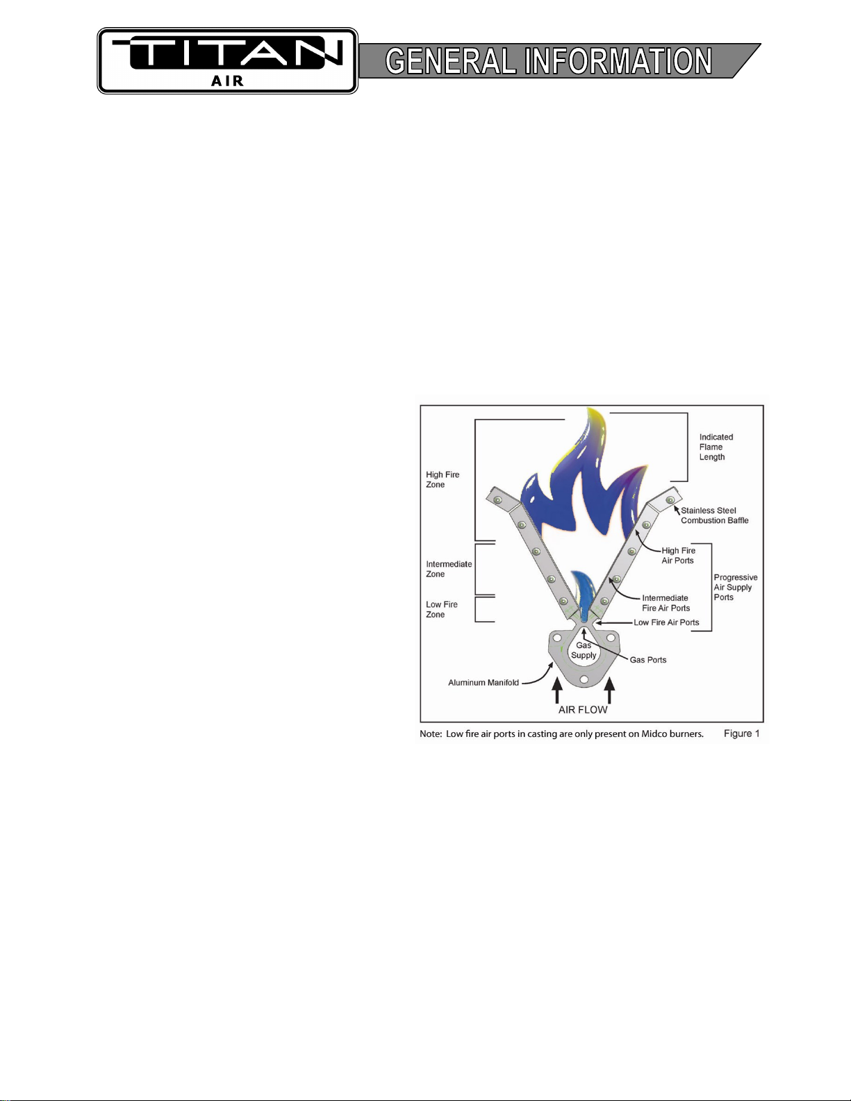
BURNER OPERATING PRINCIPLES
The direct fired burner is designed to
operate in a cabinet of flowing fresh air. Fuel
gas is fed directly to the burner; kinetic energy
of the airstream furnishes combustion air. It
will function properly at the design velocity and
pressure associated with ventilating systems.
Two speed H.O.T.™ units feature a
damper with actuator and controls to maintain
proper velocity across the burner profile as air
volume changes. Single speed H.O.T.™ units
have slide plates on either side of the burner
to allow manual adjustment of the burner
profile area.
The burner must be installed to fire with,
and parallel to, the air flow. By virtue of velocity impact and suction generated by the diverging
shape of the combustion baffles, air is induced through the air ports into the combustion zone.
Although the air supply to the burner combustion zone is constant, only some of the air is actually
mixing with the gas to produce combustion.
When a very small quantity of gas is admitted to the burner, sufficient mixing takes place in the
low fire slot where combustion takes place. Since the low fire zone is contained within the burner
casting it is effectively shielded from uncontrolled air entry.
As the gas supply is increased the flame progresses into the intermediate fire zone where an
additional supply of air is available. At higher or full capacity, mixing occurs at the larger air ports of
the high fire zone augmented by air flowing over the end of the baffles.
On a reduction of gas supply the reverse sequence takes place, the flame recedes to a location
of lesser air supply until the low fire zone is reached. The burner is suitable for a turndown range of
approximately 30 to 1.
Page 8

8
AIR SUPPLY
The supply fan is typically positioned to draw air across the burner. Air flow across the burner
must be substantially straight (laminar) and velocity must be within the proper range to develop the
desired turndown and capacity.
The direct fired burner is designed to operate in an air make-up heater with all air crossing the
burner taken directly from outdoors. Rare exceptions involve equipment that serves an unoccupied
space.
Total pressure rating of the blower includes allowance for the pressure drop through the primary
air handling unit including the burner, together with pressure losses at the inlet screen, inlet damper,
filters, outlet damper if used, plus the external pressure rating of the system.
BURNERS
Burners are purchased in 6” and 12” straight lengths and 12” tee sections and are assembled
to meet the BTU requirements of each piece of equipment.
According to national safety standards, the following factors could influence safe operation of
a direct fired air make-up unit and must be interlocked to either prevent the burner from firing or shut
it down if unsafe conditions occur.
1. AIR SOURCE – If a damper is used, it must be interlocked to prove it is open before the
blower can start.
2. BLOWER STARTER/VFD INTERLOCK – A contact proving that the blower starter is
energized or VFD is operating must be incorporated to prevent burner operation when
the blower is not operating.
3. AIR FLOW SWITCHES – Monitor the air flow (pressure drop) across the burner. The
switches (one high differential and one low differential) will not allow burner to operate if
air pressure drop across burner is outside of the high and low set points.
4. HIGH TEMPERATURE LIMIT – A manual reset high temperature limit control must be
utilized to prevent high temperature situations caused by excessive fuel pressure or lack
of air flow.
5. FLAME SAFEGUARD – Monitors the combustion process during ignition and operation
for safe conditions.
6. HIGH GAS PRESSURE SWITCH – Monitors gas pressure to the burner. This deenergizes the burner in the event gas pressure increases above its set point.
GAS CONTROLS
Titan Air H.O.T.™ equipment is constructed to meet ANSI Z83.25/CSA 3.19 standards.
Components in the gas delivery manifold on standard equipment include: two manual shut-off
valves, gas pressure regulator, two safety shut-off valves and an electronic gas modulating valve.
The pilot control includes a shutoff valve, gas pressure regulator and a pilot solenoid.
Page 9

9
ELECTRIC /ELECTRONIC CONTROLS
Titan Air H.O.T.™ units typically come standard with the following items: disconnect switch,
starter and overload assembly(s) or variable frequency drive(s), control power transformer (if a 3
wire system), air proving switches, high temperature limit, electronic flame safeguard and electronic
flame modulation with remote setpoint adjustment. Control systems can be designed to meet
specific requirements. Numerous temperature controls are available. Since H.O.T. units usually
temper outside air to replace the air exhausted from a paint booth, modulating discharge
temperature control is typical. At least one additional setpoint is usually included for the high outlet
temperature mode.
H.O.T.™ units are typically supplied with a remote control panel. This panel will include
switching for blower & burner operation and temperature setpoint(s). Timers are often included to
automate the bake cycle. Other options common for H.O.T.™ units include controls to interlock with
paint booth lights and compressed air solenoid as well as control a paint booth exhaust fan. Some
units feature operating lights, discharge temperature display, custom controls or contacts by others
to enable blower and/or burner operation.
Refer to the unit specification sheets, parts list, schematic, sequence of operation and start-up
procedure for a specific unit to determine the control options included.
IMPORTANT: If the malfunction of the heater creates a hazard to other fuel burning
equipment in the served building (i.e. supplying make-up air to boiler room) it is to be
interlocked to open an inlet air damper in case of failure.
NOTICE: The operating temperature control system must limit the discharge air
temperature from exceeding 250°F in the process air heater mode and 160°F
ventilation air heater mode.
Page 10
10
AIR FLOW SWITCH OPERATION
BURNER PROFILE AIR PRESSURE DROP
ANSI standards, Z83.25/CSA 3.19, require manufacturers to monitor air moving across the
burner for both high and low conditions. Titan Air utilizes air pressure drop across the burner to
satisfy this requirement.
Certification testing demonstrated that the burner will function properly between a low pressure
drop of 0.2" w.c. and high pressure drop of 0.95" w.c. The standards also mandate that the switches
cannot be adjustable. This makes air pressure drop across the burner profile a very important factor
at initial start up.
The design burner pressure drop at standard air conditions is 0.60” w.c. and will change as the
temperature of outside air increases or decreases from 70°F. In order for the burner to operate
within the range of the air flow monitoring switch set points, the pressure drop should be as close to
0.60” w.c. as possible.
Air pressure drop across the burner profile is dependent on OA temperature. When the burner is
off, pressure drop will climb significantly during cold weather. The burner is always off on initial start
-up. Therefore, if the burner profile air pressure drop is above 0.70” w.c. during a warm weather
start-up, it may exceed 0.95” w.c. during a cold weather start-up in northern regions. Such a high air
pressure drop would open the high airflow switch and prevent burner ignition.
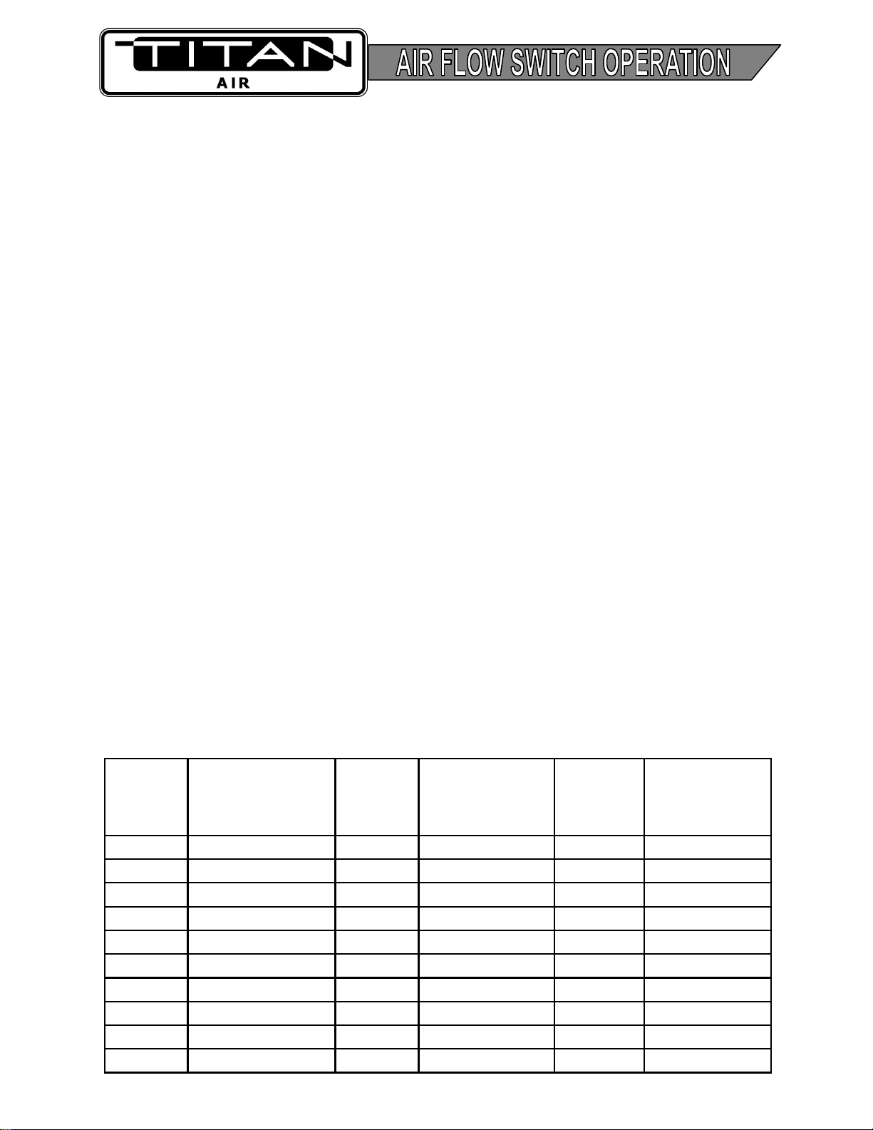
The following chart will aid in equipment set up at outside air temperatures different from 70°F
when the unit is operating with the burner off. The chart gives pressure drops, at various
temperatures, equivalent to 0.60” w.c. at 70°F.
Note that two speed H.O.T. units feature controls to maintain pressure drop across the burner as
air volume changes. Either high speed and low speed mechanical adjustments of damper actuator
travel or a dual pressure switch assembly are used to control burner air pressure drop. Burner
profile air pressure drop should be measured on high speed with the burner profile dampers near the
full open position. If the burner profile dampers open less than 50% on high speed, the unit is
probably delivering less than full rated airflow.
Burner Profile Air Pressure Drop at Various OA Temperatures (Burner Off)
OA
Temp
(˚F)
Burner
Profile Drop
(w.c.)
OA
Temp
(˚F)
Burner
Profile Drop
(w.c.)
OA
Temp
(˚F)
Burner
Profile Drop
(w.c.)
-40 0.76 10 0.68 60 0.61
-35 0.75 15 0.67 65 0.61
-30 0.74 20 0.66 70 0.60
-25 0.73 25 0.66 75 0.59
-20 0.72 30 0.65 80 0.59
-15 0.71 35 0.64 85 0.58
-10 0.71 40 0.64 90 0.58
-5 0.70 45 0.63 95 0.57
0 0.69 50 0.62 100 0.57
5 0.68 55 0.62 105
0.56
Page 11

11
PRE-INSTALLATION
Inspect the equipment making sure all parts and accessories are on the job site. Check
equipment against order and packing list. If the equipment has been sitting in storage for some
time, inspect it for moisture (from condensation, rain or snow) and/or dust accumulation. Both can
cause damage to electrical and electronic components as well as bearings and insulation.
INSTALLATION CODES
Care taken during the installation and start-up is vital to the longevity and reliability of the
equipment. Confirm that gas and electric utilities match the rating on the equipment name plate.
This heater shall be installed in accordance with local codes or, in the absence of
local code, according to National Fuel Gas Code, ANSI Z223.1/ NFPA 54, or the
CAN/ CSA B149.1 Natural Gas and Propane Installation Code.
If the heater is to be installed in an aircraft hangar, refer to ANSI/NFPA 409.
If the heater is to be installed in a parking garage, refer to ANSI/NFPA 88A.
If the heater is to be installed in a repair garage, refer to ANSI/NFPA 30A.
For installations in Canada, refer to CAN/CSA B149.1 National Gas and Propane
Installation Codes.
INSTALLATION PREREQUISITES
The heater inlet shall be located in accordance with the applicable building or
mechanical code provisions for ventilation air.
Adequate exhaust and/or relief must be provided to prevent over pressurizing the
served space when the heater is operating at its rated capacity. It should be noted
that this can be accomplished by taking into account, through standard
engineering methods, the structure’s designed infiltration rate; by providing
properly sized relief openings; or by interlocking a powered exhaust system; or by
a combination of these methods.
Heaters installed with intake ductwork must purge at least four air changes the
volume of the intake ductwork prior to an ignition attempt.
Ventilation air to the heater shall be ducted directly from outdoors when heater is
operated in the ventilation air mode.
An electric disconnect switch having adequate ampacity (see name plate on the
heater for voltage and ampacity), if not provided as part of the heater shall be
installed in accordance with the National Electric Code, ANSI/ NFPA 70.
If in doubt regarding the application of the direct fired heater, contact the sales
representative or the factory.
PAINT BOOTH HEATER INSTALLATION PREREQUISITES
Access opening(s) to the heated space must be equipped with door interlock
switch(es) to prevent the operation of the heater during a bake cycle when an
access door is open.
It is recommended to post the following warning marking at each access opening.
“Do not enter this space until the cool down cycle is complete.”
A post purge timer to purge contaminants from the space and cool the products to
avoid a burn hazard must be provided following a bake/ drying cycle.
Page 12

12
PAINT BOOTH HEATER INSTALLATION PREREQUISITES Contd.
An interlock must be provided to:
Lock out paint spraying equipment unless process heater is operating in
ventilation mode.
Lock out facility lighting with-in the heated space during bake cycle.
Ensure equipment has been operated in the ventilation mode for three
minutes or a minimum of four air changes of the paint booth volume,
whichever is greater at the start of the bake or drying cycle.
Initiate the heater fan in conjunction with the operation of the exhaust fan.
POSITIONING THE HEATER
Locate the heater exactly level, making certain minimum clearance required by local codes is
maintained between the heater and any combustible materials. See name plate on unit for minimum
recommended clearances.
When the makeup air equipment is located on a roof or at ground level on a concrete pad, the
unit intake needs to be a minimum of 24” above the roof and/ or ground to prevent the intake of
snow or splashed rain. The unit should be located in such a way to prevent prevailing winds from
blowing directly into the unit intake. If the application is critical, provisions must be made to protect
the unit inlet from the driving winds.
CLEARANCE
Select the installation location and support system (curb, stand or other) that meets or exceeds
all of the minimum safety clearance requirements.
BOTTOM
Unit should be installed to allow clearance for proper condensate trap (If applicable). Do not
install unit on combustible surfaces.
SIDES
The minimum recommended clearance on all sides of the unit except for the service side and
bottom is 6 inches.
SERVICE
The service side should have a minimum of 24 inches of clearance; however it is recommended
that the clearance be at least the width of the widest door.
Also, if the unit includes any coils or has twin blowers more clearance should be provided for
removal of those components.
The minimum clearances listed above are set, in place, by the standard in which Titan Air builds
their equipment to meet; however, one should consult with all authorities having jurisdiction to
ensure they don’t require larger clearances. Furthermore, the unit must be installed in such a way to
facilitate smooth operation and maintenance of all built in sections and components. Also, it should
be noted that the coil pull could be located on either side of the unit. Review the unit submittal
drawing for the correct direction of the coil pull.
Page 13

13
CURBING (OUTDOOR MOUNTING)
The use of a full perimeter curb or mounting rails under the heater is recommended. The only
openings in the roof should be for the supply air duct, return air duct (if required), gas and electrical
connections (if applicable). These openings must be sealed properly after installation. Titan Air
ships all curbs unassembled and un-insulated. Installing contractor supplies gaskets, cant strips,
insulation, etc.
INSTALLATION SAFETY
RIGGING
DANGER: Never enlarge lifting lug hole to accommodate larger anchor shackle.
WARNING: Never assemble unit sections or sub-assemblies together before rigging.
Always rig unit the way it was shipped from the factory.
CAUTION: It is the installer’s responsibility to confirm that the lifting equipment
capacity exceeds unit weight by an adequate safety factor. Never stack inlet hoods or
other components onto the unit as the unit is being lifted.
IMPORTANT: Apply appropriate sealant to roof curb and duct adapter(s) prior to
setting the unit in place (If applicable).
Lifting Requirements:
Protect coil connections, extending through unit casing, from damage by the
rigging cables through the use of plywood or other suitable materials.
Exercise care when moving the unit.
Rig the unit using ALL the lifting points, in a fashion that holds it level and
prevents it from tipping, falling and/ or twisting.
Spreader bars of sufficient width MUST be used across the top of the unit, to
ensure that the lifting cables clear unit cabinetry.
Utilize the same rigging and lifting methods as the ones applied to the unit, for
lifting the accessories.
Remove all wooden shipping blocks before setting unit(s) onto curb (If applicable).
After sections are set in place, assemble according to Unit Section Assembly (If
applicable).
NOTICE: Warranty does not cover damage from the unit being severely
twisted or dropped during handling.
GAS PIPING
Gas piping must be sized and installed in accordance with applicable codes. It must be able to
deliver the specified CFH and gas pressure at full flow. Refer to unit nameplate or unit specification
sheets for specified CFH and gas pressure.
NOTICE: A manual emergency fuel shut off valve is required to be installed in a
location which is accessible to personnel in case of a fire or explosion at the
equipment. This is the responsibility of the installing contractor.
Care must be taken with the gas piping to prevent problems at start-up and later during
operation. Before the union between the supply line and the unit is connected, the supply line
should be cleaned out to remove any foreign material (dirt, rust, metal shavings, etc.) and a drip leg
should be utilized.
Page 14

14
GAS PIPING Contd.
Refer to unit nameplate to determine the minimum gas supply pressure required to attain the
maximum specified gas capacity.
Suitable gas controls, regulators and valves (equipped with a diaphragm) in this unit are
furnished with an ANSI approved add-on vent limiter or have an integral vent limiter, if available.
However, final vent limiter approval will always be up to state, city or local codes. If local code
requires these components to be vented to outside, it is the responsibility of the installing contractor.
CAUTION: The heater and its individual shut off valve must be disconnected from the
gas supply piping system during any pressure testing in excess of ½ PSIG.
CAUTION: The heater must be isolated from the gas supply piping system by closing
its individual shut off valve during any pressure testing of the supply system at
pressures equal to or less the ½ PSIG.
During start-up, the technician should perform a gas leak check on all components and piping during
the heater’s normal operation. (See page 34)
DUCTWORK
Ductwork must be sized and installed in accordance with applicable codes and standards. As a
recommendation follow SMACNA guides for proper ductwork design, size and installation. A size
variation may exist from recommended duct size to unit or accessory flange size. Accessories on
the unit intake or discharge may be larger than the openings on the unit. Be sure to check the unit
submittal drawing for the correct equipment connection size. Recommended duct size applies to the
size of the duct at the connection to the equipment. Factory also recommends 2 1/2 times the
equivalent duct diameters of straight ductwork off the discharge outlet of the blower. A properly
designed duct transition from the blower outlet to a larger duct is recommended for long ducts or
ducts with numerous elbows. The unit was designed for a specific CFM and ESP (External Static
Pressure) stated on unit rating plate. The ductwork attached to the unit will significantly affect its
performance.
NOTICE: When the heater is operated as a process air heater with airborne
particulate matter in a recirculation mode, filters must be installed in the return air
duct. The particulate removal filters shall be approved by the authority having
jurisdiction. The return air duct system must also have doors/ access panels for
inspection and cleaning. The filters and duct require periodic inspection and cleaning.
NOTICE: The duct to a process air heater which will allow recirculation must be
designed to prevent recirculation of insufficiently diluted products of combustion. A
minimum amount of ventilation air must be supplied to exceed 200 CFM per 1000
CFH of natural gas based on maximum capacity of the heater plus an allowance to
sufficiently dilute the VOC’s created by the process to maintain the lower explosive
level (LEL) below a 25 percent threshold value.
On heaters mounted outdoors, discharge ductwork should be insulated to minimize
condensation during the “off” cycle in cold weather. A fresh air intake hood with bird screen is
required. Discharge ductwork on a twin blower unit must be common to both blowers.
On a heater mounted indoors with through the roof intake, a “mushroom” type intake hood is
recommended to prevent moisture entrainment. When using “through the wall” intake duct, the
intake louver should have adequate moisture baffling characteristics. All intake ductwork exposed to
Page 15

15
the heated space should be insulated. Also any ductwork passing through unconditioned spaces
must be insulated and covered with a vapor barrier.
Factory not responsible for field retro fits due to difference of the actual ESP from the designed
ESP.
SOUND AND VIBRATION CONTROL
Use of flex coupler between building ductwork and air makeup unit is highly recommended.
Vibration isolators that mount between the unit and support structure are optional and can be
supplied with the equipment for installation by others. Another option is internal isolation of the
blower/motor assembly with internal flexible connections between the blower housing and the unit
structure.
Appropriate insulation on the interior of ductwork significantly reduces sound levels.
DISCHARGE TEMPERATURE SENSOR BULB INSTALLATION & WIRING
The installing contractor may be responsible for field installation of the discharge temperature
sensor. Field installation of the discharge temperature sensor in the discharge ductwork results in a
better measurement of the average supply air temperature. For paint booth applications, the sensor
should typically be located as close to the booth’s supply air plenum as possible. Utilize shielded
cable for field installed discharge sensor wiring.
FIELD WIRING
Power supply wiring should be routed from a dedicated branch circuit per schematic. Depending
upon how the equipment was ordered, a single point power connection may be subdivided to
individual loads or multiple power supply circuits may be required.
If an intake or discharge damper was ordered as a loose accessory, it will have to be mounted
as specified in the Damper Installation Instructions found on page 24 and the actuator must be
wired. The remote panel must be mounted in a convenient location and wired to the unit. Interlocks
between the exhaust, unit and possibly spray booth will have to be connected by field wiring.
Carefully review the schematic and associated schematic symbol legend. Note that legend may
be on the parts/legend sheet rather than on the schematic.
Many codes require that low voltage wiring be routed in separate conduit from line voltage
wiring. If low voltage wiring is routed with 120 VAC control voltage wiring, it must be placed in
shielded cable(s) with appropriate insulation rating. Even if low voltage wiring is routed in separate
conduit, very low voltage sensor outputs and actuator control signals should be routed in shielded
cable.
NOTICE: All field wiring must conform to N.E.C. and/or any state or local codes.
POST INSTALLATION
Sealing integrity should be rechecked on a yearly basis. Most of the unit will likely be under a
negative pressure when the blower is operating. Dirt and moisture can be drawn into the unit. Check
for water in outdoor units after operation during a rain shower. Water damaged parts are not covered
by Titan Air’s warranty.
Page 16

16
Horizontal Unit-Supporting Options
Curb
Curbs are to be assembled in the field.
Assemble according to the letters marked
on the top of each curb piece using factory
supplied fasteners.
Caulking or Gasket material
(supplied by others)
Accessory-
Horizontal Unit Supporting Options
Recommended option for supporting
accessories on a flat roof:
Other method of installation using sheet
metal support legs.
IMPORTANT: Not recommended
for any unit larger than 125
model.
Typical Equipment Support
(by others)
Attach support brace to accessory seam
using field supplied fasteners.
Bent, 16 gauge (if supplied by factory),
sheet metal support brace.
6 X 6 inch sheet metal pad welded to
the support brace (if supplied by factory)
Wood Block (supplied by others)
Page 17

17
MULTI-SECTION EQUIPMENT
Horizontal Configuration
Before beginning:
Be sure to check the tightness of all bolts,
nuts and setscrews, which could have loosened
during shipping.
Rotate blower fan shaft(s) by hand to make
certain there is no interference or rubbing
between components.
Verify installation surface is level before
proceeding with unit installation.
Locate mounting hardware:
Items included: Caulk, Caulk Tape,
Fasteners
Check all sections, of the unit, thoroughly for
assembly hardware. The assembly hardware
will be found packaged in either a clear plastic
bag or corrugated box.
NOTICE: There may be more
than one package of assembly
materials provided.
1. Apply provided caulk tape to the face of
the joint to be bolted together, on one side only
as shown below, before assembly. Ensure
there are no gaps in the caulk tape when
applying. Do not cover bolt holes with caulk
tape.
2. Locate and match each section letter on
the service side of the unit with the
corresponding letter on the other section. In
addition, also refer to the unit submittal drawing
for proper assembly order.
3. Pull sections together at the lifting lugs
using, two, half inch rods w/ nuts and large
washers as shown below.
Caulk Tape
Caulk
Tape
Page 18

18
4. Use the provided
fasteners to secure the
seam at the top and
bottom before setting the
next section into place.
IMPORTANT:
Use all of the bolt
holes in the seam
for joining the unit
sections together
and then tighten
accordingly.
Trim off the excess
caulk tape squeezed out
of the joint at each unit
joint to provide a clean
appearance.
5. After all of the sections are bolted
together, caulk the external section seam(s) to
provide a water tight seal.
IMPORTANT: Check all external
sheet metal seams for caulk
shrinkage and re-caulk if
necessary. Titan Air. does not
warranty water damage units.
Unit seam sealing integrity
should be rechecked on a yearly
basis.
NOTICE: Access door swings
MUST be kept free of installation
piping and wiring to allow for
service and maintenance.
8. Roof Cap Installation
Apply caulk to section roof tee before
placing on the splice cap.
Fasten splice cap to roof tee using the
provided self tapping screws from the top.
Caulk around all edges of the splice cap.
Caulk
Page 19

19
MULTI-SECTION EQUIPMENT
Vertical Configuration
Before beginning:
Be sure to check the tightness of all bolts,
nuts and setscrews, which could have loosened
during shipping.
Rotate blower fan shafts by hand to make
certain there is no interference or rubbing
between components.
Verify installation surface is level before
proceeding with unit installation.
Locate mounting hardware:
Items included: Caulk, Caulk Tape,
Fasteners
Field Supplied Hardware: Anchoring studs
along with nuts and washers
Check all sections, of the unit, thoroughly for
assembly hardware. The assembly hardware
will be found packaged in either a clear plastic
bag or corrugated box.
NOTICE: There may be more
than one package of assembly
materials provided.
1. Anchor the stand on a level concrete pad
using studs or by other means. Each stand foot
pad needs to be secured.
NOTICE: For indoor units, the
stand must be enclosed
(sometimes height is increased.)
A transition (by others) must be
made from enclosed stand intake
opening to the intake damper or
louver (a size variation may
exist.)
Flat & Level
Concrete Pad
Set in Place Stud or
Wedge Type Anchor
Flat
Washer
Hex Nut
Page 20

20
2. Apply provided caulk tape to one side of
the joint to be assembled. Apply tape toward the
outside of the bolt pattern as seen below.
Ensure there are no gaps in the caulk tape
when applying. Do not cover the bolt holes with
caulk tape.
3. Locate and match each section letter on
the service side of the unit with the
corresponding letter on the other section. In
addition, also refer to the unit submittal drawing
for proper assembly order.
4. Lift blower section and center it over
burner section with the unit section letters lined
up. After blower section is set in place use drift
punches to line up seam bolt patterns. Fasten
sections together using the provided bolts, nuts
and washers filling all of the seam holes.
Caulk Tape
Page 21

21
5. Caulk around the outside of each section
seam.
IMPORTANT: Re-caulk unit
lifting lugs after assembly. Check
all external sheet metal seams
for caulk shrinkage and re-caulk
if necessary. Titan Air. does not
warranty water damage units.
Unit seam sealing integrity
should be rechecked on a yearly
basis.
Caulk
Page 22

22
Accessory Installation
NOTICE: Unit accessories may
be larger than unit intake and
discharge opening or flanges.
Due to infinite installation
possibilities, a section of
ductwork or transition may be
required for proper accessory
mounting (by others).
IMPORTANT: Installer MUST
SUPPORT accessory items
from a rigid point or points to
ensure solid mounting using field
or factory supplied hardware.
DESIGN CONSIDERATION:
Titan Air strongly recommends
using a flex coupler between the
AMU and Ductwork.
Refer to Field Wiring section, under the
installation section, for instructions on wiring the
damper actuators.
Design Requirement: If intake accessories
are supplied by others, the design shall
minimize entry of snow/ rain and include an
intake screen to meet ANSI standards.
Accessories on large equipment may be
shipped in two pieces for field assembly. As a
result, two damper actuators may need to be
field wired.
Horizontal Unit
Before beginning:
Verify with roofing manufacture the method
of installation preferred for supporting
accessories (Rooftop Units Only).
Locate assembly supplies:
Items included: Support Brackets (optional)
Field supplied hardware:
Caulk, Caulk Tape, Fasteners (Self tapping
screws and ¼ inch bolts/ nuts/ washers)
1. Match serial number on the accessory to
unit name plate inside control vestibule door.
2. Check unit submittal drawings to verify if
unit accessories need a transition to match up
with the air handler unit intake or discharge
opening.
Support
(by others)
Transition may be
required to interconnect
accessories and the
AMU (by others)
HOOD
FILTER
RACK
AMU
Page 23

23
3. Apply caulk tape (field supplied) directly
to the flange, below the screw pattern of the
joint to be fastened together.
4. Hoist accessory using all lifting lugs, if
provided; otherwise, a sling, to lift accessory
and center it over the panel opening.
5. Affix the accessory to the unit using (field
supplied) self tapping screws. Make certain
every pre-punched hole in the flange is used in
fastening.
6. Repeat steps three through five to attach
the hood to the filter section; except in step five
substitute ¼ inch bolts in for self taping screws
to attach the hood to the filter section.
7. After all of the accessories are installed,
caulk each seam to provide a water tight seal.
IMPORTANT: Re-caulk
accessory lifting lugs after
assembly (if applicable). Check
all external sheet metal seams
for caulk shrinkage and re-caulk
if necessary. Titan Air. does not
warranty water damage units.
Seam sealing integrity should be
rechecked on a yearly basis.
NOTICE: Access door swings
MUST be kept free of installation
piping and wiring to allow for
service and maintenance.
Caulk Tape
Caulk
Page 24

24
Intake Damper Mounting
Follow the Horizontal Accessory Installation
instructions for proper installation and the
diagrams below for mounting location of the
intake damper.
Indoor Installation Location:
Outdoor Installation Location:
Discharge Damper Mounting
Follow the Horizontal Accessory Installation
instructions for proper installation and the
diagram below for mounting location of the
discharge damper.
NOTICE: If the
Discharge Damper is
being mounted within
two to three duct
diameters from the unit
discharge opening
Titan Air highly
recommends the
discharge damper be
mounted so the blades
are orientated
vertically. (If possible)
IMPORTANT: Titan Air
also highly recommends
the discharge damper be
mounted at the wall or
ceiling indoors. However, if
the damper cannot be
mounted indoors the
damper actuator MUST BE
PROTECTED from the
outdoor elements (if
applicable).
BOTTOM VIEW
IMPORTANT: Intake
damper should be
mounted at the building
wall or ceiling.
INTAKE
DAMPE
FILTER RACK
(SIDE VIEW)
UNIT
IMPORTANT: Titan Air recommends the
intake damper be mounted with the damper
actuator facing the service side of the unit.
Make certain the damper actuator is
PROTECTED from the outdoor elements
with a sheet metal cover.
INTAKE
DAMPER
FILTER RACK
HOOD UNIT
Page 25

25
Vertical Unit Discharge Diffuser
Mounting and Supporting
Ductwork between AMU and diffuser or
discharge damper and diffuser is supplied by
others.
Support diffuser at two points using field
supplied materials (See example below).
Square
Tubing
DISCHARGE DAMPER
Secure turning vanes once
adjusted in the field (by others)
Mount discharge
diffuser after discharge
damper (if applicable).
Accessory Supporting
Example
Threaded Rod
(by others)
Page 26

26
GENERAL MAINTENANCE
Visit http://www.titan-air.com/ and click on “Tools & Resources” for more detailed
maintenance information.
As with any equipment or machinery, a maintenance program should be implemented.
Equipment maintenance should include the following:
Check filters and clean or replace as needed.
Check burner and flame rod - clean if necessary.
Check belts, belt tension and sheave alignment. (Do not over tension.)
Confirm smooth operation of dampers.
Lube bearings.
Check all hardware (bearings, etc.) for tightness.
Check settings for all controls.
Check duct connections for leaks.
Re-caulk seams if needed.
Perform complete start-up procedure once per year (prior to heating season).
FILTERS
Dirty or clogged filters will restrict air flow which in turn affects the equipment performance.
Therefore, it is necessary to check filters on a regular basis. Several standard filter types are
available including 2" pleated 30% efficient, 2" disposable fiberglass, 2" linked panel, and 1" or 2"
cleanable filters.
Cleanable filters should be removed from the filter rack and sprayed with a low pressure water.
Always spray these filters in the opposite direction to air flow and apply new coating to filters when
dry.
Note that cleanable filters alone may not adequately protect a coil from dust and dirt
accumulation.
Filters in an unheated outdoor airstream can “freeze-up” when the humidity is high (foggy)
and temperatures are near freezing.
Method of Prevention:
Install pre-filters in the outdoor airstream that can be removed during such weather.
Page 27

27
BURNER
NOTICE: Vertical Unit Burner Access: Filter rack can be slid out through the unit door
to allow access to the backside of the burner.
Maintaining the pilot assembly is essential to reliable operation. During pre-heating season
maintenance, the burner should be lit numerous times to confirm reliability. If ignition system
components require servicing, pay attention to the following:
Handle porcelain spark rod and flame rod with care. Small cracks lead to
intermittent ignition problems.
Midco burners utilize the pilot gas tube as a ground point for the ignition rod.
Keep this grounding point free from scale or other contaminant build-up.
Ignition wire routing should remain separated from sheet metal cabinet to
maintain optimal spark strength.
Dielectric grease is utilized inside of the ignition and flame sensor connection
boots to limit potential for moisture in the connection.
Maintaining low pilot regulator output pressure typically produces reliable ignition.
Excess pilot pressure creates a gas rich region that will not ignite consistently.
The pilot solenoid is disabled following main flame ignition. The low fire setting
must be high enough to maintain a proper amplified flame rectification signal.
Check that burner baffles are firmly attached to each other and to burner casting. Do not use
excessive force on screws in casting. Clean baffles with wire brush if needed.
Burner orifices may need to be re-drilled due to rust or other build-up. Burners with aluminum
castings will rarely require orifice cleaning. Use drill bit sizes listed below.
Fuel Type Burner Model Orifice Size
Natural Gas Eclipse AH-MA 2.4 mm Bit
Natural Gas Midco HMA-2 or 2A 1/8” Bit
LP Gas Eclipse AH-MA 2.0 mm Bit
LP Gas Midco HMA-2 or 2A 1/8” Bit
Low Fire Air Ports Midco HMA-2 or 2A
#43 Bit
Page 28

28
GENERAL V-BELT DRIVE TIPS
Keep the belts and sheaves free from foreign materials that may cause slippage
or damage to the belt and sheave surfaces.
Maintain sheave alignment.
Inspect the V-belt drive periodically. Re-tension the drive belts if they are slipping.
NOTE: Optimal belt tension is the lowest tension at which the belts will
not slip under peak load. Peak load typically occurs at start-up.
Over tensioning belts can cause premature bearing, sheave and belt failure.
Particular attention should be given to these conditions:
Worn groove sidewalls
Shiny sheave groove bottom
Wobbling sheaves
Damaged sheaves
BELT TENSION
Proper sheave alignment and belt tension are critical to belt and bearing service life. Incorrect
belt tension or misalignment of sheaves can cause any of the following:
Premature failure of bearings.
Premature failure of belts.
Reduced air volume.
Noise and vibrations.
Each Titan Air unit has as standard equipment an adjustable motor base. To adjust the belt
tension, loosen the motor hold down bolts and adjust the slide base with adjusting bolt(s) on the end
of the base (larger bases will have 2 adjustment bolts). Use a belt tension tester and associated
tables to determine proper tension. Re-tension after the first day of operation with new belts and
periodically thereafter.
Common belt tension gauges will specify a force required to produce a deflection of 1/64” per
inch of span. The force required to achieve this deflection is typically in the range of 3 lbs for Abelts, 5 lbs. for B-belts, and 15 lbs. for 5V belts. See Figure below.
Page 29

29
SHEAVE ALIGNMENT
With the use of a straight edge, sheave alignment can be checked quickly and accurately. One
of the sheaves will have to be loose on its shaft in order to make adjustment. Adjust until all 4 points
are in contact with the straight edge (see Figure below). Repeat on the other side of sheaves and
then re-tighten.
If a face width variation exists, measure the difference between each side of the narrowest
sheave and adjust until both sides are an equal distance from the straight edge.
BELT REPLACEMENT CONSIDERATIONS
IMPORTANT: Do not force belts onto sheaves by using a pry bar or by rolling the
sheaves.
NOTICE: Match the size of the new belts to existing ones, except if the sheave
groove size was adjusted. Replace drive belts in complete sets. Purchase set of belts
from the same manufacture.
Page 30

30
BLOWER BEARINGS
Bearings must be checked during each periodic maintenance inspection. Bolts and set screws
should be checked for tightness and the bearings may need lubrication. Refer to website for specific
manufacturer cut sheets pertaining to bearing maintenance.
Bearing Lubricate: Any good quality lithium or lithium complex base grease using mineral
oil conforming to NLGI grade 2 consistency and an oil viscosity of 455-1135 SUS at 100˚F (100-250
cSt at 40˚C) may be used for re-lubrication.(Only applicable if unit blower bearings are Browning AH
(Air Handler))
IMPORTANT: The following table is intended only as a guide to aid you in setting up
your own schedule.
LUBRICATION GUIDE FOR BLOWER BEARINGS
MOTOR BEARINGS
Motor bearings in a clean environment should be lubricated every 2 to 3 years. Under more
severe conditions of dirt or moisture, lubrication may be required every 6 months to 1 year. Refer to
website for specific manufacturer cut sheets pertaining to motor bearing maintenance.
Typical motor bearing lubrication procedure follows:
Remove fill and drain plugs.
Clean drain port of hard grease (with wire if necessary).
Add grease (cavity should be no more than ½ full.).
Start motor and let run for 10 minutes.
Wipe off any drained grease and replace fill and drain plugs.
IMPORTANT: Avoid adding an excessive amount of grease since this a common
cause of motor failure.
BLOWER WHEEL
Ensure that blower hub is securely fastened to shaft. Inspect blower wheel and blades for signs
of damage or cracks. Clean blades if necessary to maintain proper balance and performance.
Avoid use of excessive grease on blower bearings that can coat fan blades and attract dirt.
Operating Conditions Bearing Temp. (˚F) Grease Interval
Clean 32 – 120 6 – 10 ,months
120 – 150 1 – 3 months
150 – 200 1 – 4 weeks
32 – 150 1 – 4 weeks Dirty
150 – 200 Daily – 1 week
Moisture 32 - 200
Daily – 1 week
Page 31

31
FIREYE MICRO M SERIES LED INDICATING LIGHTS – STANDARD OPERATION
Operating Control - Energized whenever the burner control switch is on and
power is applied to terminal #7 in the flame safeguard.
Interlock - Illuminated solid when power is applied on terminal # 6 in the flame
safeguard to indicate that the air flow switch and other control & limit switches are
closed. This light flashes once per second if the user has selected the fan-only
mode (summer) or if an airflow switch or other safety circuit switch is open.
PTFI - Illuminated only during the pilot trial for ignition period.
Flame - Illuminated when flame signal is detected.
Alarm - LED will flash once per second when an alarm condition is detected.
Symbol Legend
Flashing
Light
Solid Light Light Off
Lockout Description OPR CNTL INTRLK PTFI FLAME ALARM
Line Frequency Noise Detected
Flame Fail – PTFI
Fault Unknown
Amplifier High Count Fail
Flame Fail – MTFI
False Flame – Standby
Interlock Open
Interlock Closed
Chassis Opto
Flame Fail – Auto
Check Chassis
Check Programmer
Amplifier Auto Check Fail
Check Blown Fuse
Check Sensor
Page 32

32
FIREYE MICRO M SERIES LED INDICATING LIGHTS – ALARM MODE
Line Frequency Noise Detected - At start up, the MICRO M measures the AC line to
determine if the input is 50 Hz or 60 Hz and set its flag accordingly. As the system is
running, line frequency is constantly monitored. Outside interference causing a
momentary shift in line frequency could be from SCR controls, VFD’s, etc.
Flame Fail - PTFI - No flame signal present at the end of pilot trial for ignition period.
Fault Unknown - A catch all message when, under certain high noise conditions, the
lockout message may become garbled and not translatable into any existing
message
Amplifier Count Fail - A message used to detect a failed amplifier module that would
generate an inordinate amount of pulses to micro computer, usually due to a shorted
transistor or oscillating electronic filter.
Flame Fail - MTFI - No flame signal present during main burner trial for ignition
period.
Flame Fail - Standby - Flame signal present, for a constant 60 seconds, while control
is in standby or off condition.
Interlock Open - Interlock safety circuit (terminal #6) has been detected open for
longer than ten minutes during the purge cycle or during main flame period on MEP
562.
Interlock Closed - If selected by dip switches, air flow or interlock switch (terminal #6)
is closed 30 seconds after the start of a cycle or when terminal #7 is closed. Titan Air
does not use this function.
Chassis Opto - Opto coupler located on chassis has been found to be defective. Opto
couplers are checked every 1/2 cycle of the AC main(s) to ensure they are off during
the negative 1/2 cycle.
Flame Fail Auto - If dip switches selected for non-recycle, no flame is detected during
the run cycle or main flame period.
Check Chassis - At beginning of cycle terminal #5 is energized.
Check Programmer - At beginning of cycle terminal #3 is energized or an internal
diagnostics test for the Micro controller has failed.
Check Amplifier - Diagnostic problem with amplifier has been found.
Amplifier Auto Check - The amplifier is checked every 8 seconds by the micro
computer to assure it is responding properly.
Check Blown Fuse - At the end of pilot try for ignition, no flame is detected and no
power is present on terminal #3, indicating the fuse, located on chassis, is blown.
Check Scanner - The UV self check scanner (UV equipped units only) is producing
flame pulses during the shutter closed period due to a malfunctioning shutter or a runaway UV tube.
Page 33

33
GENERAL START-UP INFORMATION
Even though Titan Air equipment is tested prior to leaving the factory, a complete field start-up is
essential for proper operation of the equipment. Qualified individuals should perform installation,
start-up and maintenance tasks.
The factory cannot duplicate the conditions the equipment will see in the actual installation (i.e.
gas pressure, static pressure, desired control settings, etc…). For this reason there are field
adjustments that have to be made. Performing a complete start-up procedure will help ensure that
correct adjustments are made and correct operation is verified. A step-by-step start-up procedure is
provided on subsequent pages. While working through the start-up procedure, record information
on the start-up checklist and return to Titan Air to validate the equipment warranty. The start-up
checklist is provided on cardstock with Titan Air’s address pre-printed on one side.
Because most component failures occur during start-up, it is very important that the function of
every component be checked out during start-up. It is just as important that the start-up technician
realize the malfunction of a component may be caused by other factors (i.e. air flow, gas pressure,
field wiring, etc…) and should fully investigate a component malfunction and its cause before
replacing the component.
Titan Air checks out all returned components and has found approximately 70% of returned parts
are in full operational condition. This history has proven that a little extra time invested in
troubleshooting will often save the considerable investment in parts, time, and paperwork associated
with replacing components.
SUGGESTED TOOLS AND INSTRUMENTS NEEDED FOR START-UP:
Volt/Ohm Meter
Ammeter
Tachometer (preferably non-contact style)
Thermometer (preferably digital with remote probes and sufficient lead lengths)
Gas pressure gauge (-10” to 0 to +10” of water column typical scale)
Air differential pressure gauge (-2” to 0 to +2” of water column typical scale)
Standard Hand Tools
Additional items for Maxitrol Series 14 or 44 temperature controls:
10,000 Ohm potentiometer
½ watt, 10,000 Ohm resistor
½ watt, 2,000 Ohm resistor
Additional items for temperature controls using Digital Programmable Controller:
1,070 Ohm resistor (supplied)
Page 34

VALVE LEAK TEST
This is a test for checking the closure tightness of the gas safety shutoff valve. It should be
performed by trained and experienced technicians. This test should be part of the scheduled
inspections and maintenance procedures.
Close the upstream manual gas valve.
Make sure manual test cock on leak test assembly is closed.
Remove the test plug on leaving side of gas valve.
Close the downstream manual gas valve.
Open the upstream manual gas valve.
Through the safety system enable the gas valve momentarily.
Immerse a ¼” tube vertically into a jar of water.
Slowly open the test cock on the leak assembly.
Once the rate of bubbles through the test assembly stabilizes, count the number
of bubbles appearing during the ten second time frame. Each bubble is
approximately 0.001 cfh.
Do this test for each shut off
valve.
Reference below leak test assembly
and leakage rate chart.
Pipe Size (in) Medium
Allowable
Leakage SCCH
Max. # of
Bubbles in 10 Sec.
Min. # of sec.
for 10 bubbles
3/8 & 1/2
.64 gas 294 7 13
1.57 LP 188 4 20.4
3/4 & 1
.64 gas 301 7 12.7
1.57 LP 192 5 19.9
1-1/4 & 1-1/2
.64 gas 532 13 7.2
1.57 LP 341 8 11.2
2
.64 gas 578 15 6.6
1.57 LP 370 9 10.3
1-1/2
.64 gas 752 19 5.1
1.57 LP 481 12 8
3
.64 gas 925 24 4.1
1.57 LP 592 15 6.5
Page 35

UNIT SPECIFICATIONS
Rep Job # Serial #
Sales Rep
Rohner
Quote #
16847
Revision
4
Job Name
R20200704.0
Date
01/20/21
18349
Tag #
Airhandling Specifications
Model:
CFM:
ESP ("w.c.):
Function:
Systems:
Location:
Configuration:
Elevation (ft):
TSP ("w.c.):
Fan Type:
Fan Model:
Fan RPM:
Fan BHP
TA-125 NG HLH H.O.T
20800 (20800)
1
High Outlet Temperature | HOT
HOT | Recirculating Cure
Indoor
HLH
0
2.82
FC DWDI
Lau A25-25H
660
16.7
Unit Control Summary
Controls:
BMS Comm.:
Enclosure:
Remote Panel:
Booth Manufacturer Temp Control
Remote Panel | None
Voltage and Supply Motor Specifications
Power Supply:
Motor HP:
Motor Type:
NEC Motor FLA:
Unit FLA:
SCCR:
480V, 3PH
20 HP
1750 rpm ODP Premium E
27
35.6
5 kA RMS Symmetrical at 480 VAC Maximum
Exhaust Fan Motor VFD Specifications
Power Supply:
Motor HP:
VFD Control:
VFD Location:
NEC Exh. FLA:
480V, 3PH
1 @ 5 HP
By Booth Manufacturer
Mounted in Unit Vestibule
7.6
Unit Construction
Exterior: Casing Type: Insulation:
Liner: Ins./Liner Loc.:
None
Single Wall Insulated
Entire Airstream
1" 1.5#G-90
Gas Heat Source
Heating Type: Gas Type: Gas Pressure:
Agency: Temp Rise: BTU/HR Min:
BTU/HR Max:
Direct-Fired 14" - 1#
STD-ANSI
2288000
NG
100 (100) 91520
2/16/2021 1:46:07 PMTitan Air, LLLP. - Kyle Kittelson
Page 36

Model: TA-125 NG HLH H.O.T
UNIT SPECIFICATIONS
Rep Job # Serial #
Sales Rep
Rohner
Quote #
16847
Revision
4
R20200704.0
Date
01/20/21
18349
Tag #Job Name
Optional Equipment Included:
- Mixing Box (By Titan Air)*
- 20 Percent Cure Mode Outside Air
- Intake Damper & Actuator*
- Type: Standard
- Finish: G-90
- Mixed Air V-Bank Filter Section*
- Filters: Linked Panel MERV-8
- Finish: G-90
NOTE: Options Ending With * Are Shipped Loose For Job Site Installation
Optional Controls Included:
- ETL Label (ANSI Z83.25 / CSA 3.19)
- HOT Package: Spray Booth | Controls by Booth Manufacturer
- Door Interlocked Non-Fused Disconnect
- Low Fire Start
- High Gas Pressure Switch
- Clogged Filter Switch | Switch Only
- Electronic High Temp. Limit
- VFD by Booth Manufacturer
- Supply/Exhaust Motor Circuits Sub-fused
- Air Handler Ducted Directly to Paint Booth
- OA Proving Switch
- RA Blade Switch
- Rohner PLC & VFD installed by Titan
- 160° F Maximum Discharge Temperature
2/16/2021 1:46:09 PMTitan Air, LLLP. - Kyle Kittelson
Page 37

FILTER
ACCESS
12) 20x25x2
20x30x1
DAMPER/
ACTUATOR
ACCESS
40x40x1
BLOWER/
MOTOR
ACCESS
40x40x1
ELEC./
GAS TRAIN
ACCESS
NTS
SERVICE ELEVATION
NTS
PLAN VIEW
NOTE:
ACCESSORIES ARE LARGER THAN OPENINGS
AND ARE SUPPORTED BY OTHERS
REV DATE DESCRIPTION INITIALS
- 10/22/20
ORIGINAL SN-18349 FROM Q-16847
AF
- 10/22/20
MOVE RA FROM BACK TO BOTTOM OF MIXING
BOX, CHANGE FROM HRD TO HRH
AF
- 12/14/20
UPDATE FROM HRH TO HLH; AND MOVE RA
FROM BOTTOM TO BACK PER CUSTOMER
AF
- 1/21/21 SUBMITTAL APPROVED AF
QUOTE NUMBER:
SERIAL NUMBER:
NOTICE:
REP. NAME:
JOB NAME:DRAWING NAME:
DESCRIPTION:
DRAWN BY:
DRAWN DATE:
SHEET #:
ISSUE #:
SCALE:
DRAWING NUMBER:
CONFIDENTIAL PROPERTY OF TITAN AIR
LLLP. INFORMATION CONTAINED
ON THIS DRAWING IS CONFIDENTIAL IN
NATURE, IT MAY NOT BE REPRODUCED OR
RELEASED WITHOUT PRIOR WRITTEN
CONSENT OF TITAN AIR INCORPORATED.
WL/AF
TA-125 HLH HOT
CUSTOM
18349
16847-4
ROHNER
R20200704.0
0-00-000-00001/25/2021
- = - - OF -
00
12
95
64
20
44
ACCESSORY
SIZE
48
50
48
50
2
36
ACCESSORY
SIZE
40
GAS INLET
VESTIBULE VENT
W/FAN
POWER ENTRY LOCATION
(OPTIONAL)
INTAKE DAMPER
MOUNT AT INSIDE WALL
(DUCT BY OTHERS)
20% OA OPENING
(7
1
2
X50)
4)25X60 LP
ROHNER PLC
CONTROL PANEL
2
48
ACCESSORY
SIZE
2
2
36
ACCESSORY
SIZE
12
43
2
60
ACCESSORY
SIZE
70
14
RA OPENING
ON OPPOSITE
SIDE
42
ACCESSORY
SIZE
4
Page 38

AIR MAKE-UP UNITS WITH DISCHARGE TEMPERATURE CONTROL VIA PLC BY
ROHNER AND RECIRCULATION IN BAKE MODE
SUMMER-PAINT MODE:
1. Start interlock (by others) closed and burner enable interlock (by others) open (see
schematic).
2. Damper (optional discharge or intake) will open. Note that this optional damper is
separate from the dampers on the recirculation mixing section.
3. Damper interlock switch closes, sending signal to PLC (by others).
4. PLC will energize the supply motor VFD (by others).
WINTER-PAINT MODE:
1. Start interlock and burner enable interlock (both by others) closed (see schematic).
2. Damper (optional discharge or intake) will open. Note that this optional damper is
separate from the dampers on the recirculation mixing section.
3. Damper interlock switch closes, sending signal to PLC (by others).
4. PLC will energize the supply motor VFD (by others).
5. Air Flow switch (P-1) makes when pressure drop across burner profile is sensed.
6. Air Flow switch (P-1A) monitors pressure drop across burner profile and will open
in the event the pressure drop increases above set point.
7. Manual reset high temperature limit (TL-1) is a normally closed safety switch and
will trip when discharge temperature increases above its set point (typically 225°F).
8. High (P-3) and low (P-2) gas pressure switches protect against abnormal gas
pressure and are manual reset safety switches.
9. Pre-purge (built into FS-1) clears cabinet of combustible gases before ignition.
10. Flame safeguard relay (FS-1) monitors the ignition and burn process. If abnormal
conditions exist, the control will shut down the unit. FS-1 is a manual reset control.
11. Discharge air temperature is controlled by the PLC with an output to the
modulating gas valve actuator (VM-1). PLC will keep VM-1 in the minimum
position until the flame is proven.
12. When the unit is shut off there is a fifteen second post purge (built into FS-1). The
blowers will operate for fifteen seconds after start interlock is opened.
BAKE MODE:
1. Unit operating in paint mode described above.
2. Bake mode interlock (by others) closed.
3. Following purge cycle, 90% OA damper closes and recirculation damper opens.
Refer to linkage adjustment instructions in operating and service manual if
percentage of outside air needs to be changed.
4. Burner circuit will be enabled and discharge temperature is controlled by PLC.
5. All burner safety controls function as in the winter-paint mode.
In all modes, exhaust fans interlocked with the unit or building relief must be provided by
others to ensure proper ventilation.
amu rohner plc recirc hot 2004.doc
Page 1 of 1
Page 39

Model: TA-125 NG HLH H.O.T
Man. Part # QtyAbbr. Description
UNIT PARTS LIST
Rep Job # Serial #
Sales Rep
Rohner
1Square D 9007MS01S0200 RA Damper Blade SwitchBS-1
1Belimo NFBUP-S Intake Damper ActuatorDM-1
1Belimo NFB24-MFT OA Damper ActuatorDM-3
1Belimo NFB24-MFT RA Damper ActuatorDM-3A
1Fireye MERT4 Flame Safeguard AmplifierFS-1
1Fireye 61-3060 Flame Safeguard BaseFS-1
1Fireye MEC120 Flame Safeguard ChassisFS-1
1Fireye MEP537 Flame Safeguard Programmer ModuleFS-1
1Mersen US6J3I 3-pole Class J Fuse HolderFU-1
3Mersen HSJ35 Class J High Speed 35a 600vac FuseFU-1
2Mersen ATQR11/2 600 VAC - Class CC Time Delay 1.5 AmpFU-2
1Mersen TRM3 250 VAC - Midget Type: 3 AmpFU-3
1Mersen USCC3I 3-pole Class Cc Fuse HolderFU-4
3Mersen ATMR15 Fus Atmr15 - Class Cc Fast Acting 15a 600vac FuseFU-4
1Baldor EM2515T 20 HP Motor(24A@460V,48A@230V,52A@208V)MT-1
1Cleveland DDP-109-187 Airflow Switch (0.2" & 0.95")P-1
1Dwyer ADPS-04-2-N Clogged Filter SwitchP-4
1Cleveland ANA-126-310 Air Flow Switch (0.2" Set Point)P-5
1Mersen MPDB63133 Power Distribution BlockPB-1
3Mersen MPDBC6263 Power Distribution Block CoverPB-1
4Idec SJ2S-07LW Relay BaseR-
1Idec RJ2S-CL-A120 120 VAC RelayR-1
1Idec RJ2S-CL-A120 120 VAC RelayR-2
1Idec RJ2S-CL-A120 120 VAC RelayR-3
1Idec RJ2S-CL-A120 120 VAC RelayR-4
1ABB OHB65J6 Disconnect HandleSW-1
1ABB OXP6X265 Disconnect ShaftSW-1
1ABB OHZX10 Disconnect Shaft GuideSW-1
1ABB OT63F3 Equipment DisconnectSW-1
1Carling 111-16-73/18 Service SwitchSW-5
1Carling 111-16-73/18 Service SwitchSW-6
1Senasys 2511F003-351 Vestibule Cooling StatT-11
1Eaton TRL04 Time RelayTDR-9
1Future Design FDC-L91-4110 High Temperature LimitTL-1
1Future Design DRA16 Plastic MountTL-1
1Hammond PH250MLI-FK Control TransformerTR-1
1Allanson 2260-P Ignition TransformerTR-2
1Honeywell AT120B1028/B 24 Vac TransformerTR-3
1ACI A/100-3W-D-12"-GD High Temp Limit SensorTS-7
1SC120-W5 Finger Guard For Vestibule Ventilation FansVF-1
1Mechatronics UF12A12-BTH Vestibule Ventilation FanVF-1
1Belimo LMCB24-SR-T Gas Valve ActuatorVM-1
1Lau 05038213C A27-27H Blower Assembly w/ 2-3/16" Bore
2Browning VPB-235-AH Bearing 2-3/16"
2Hammond FG4 Control Trans. Fuse Cover
25VX-&' Drive Belt
1OVH 256B2 Motor Base Motor Base
1SDS 1-5/8 QD Bushing
1SF 1-15/16 QD Bushing
Quote #
16847
Revision
4
R20200704.0
Date
01/20/21
18349
Tag #Job Name
2/16/2021 1:46:09 PMTitan Air, LLLP. - Kyle Kittelson
Page 40

Model: TA-125 NG HLH H.O.T
Man. Part # QtyAbbr. Description
UNIT PARTS LIST
Rep Job # Serial #
Sales Rep
Rohner
12/5V550SDS QD Sheave
12/5V1400SF QD Sheave
15102-08-12 72"W X 60"H Standard Intake Damper - 72 X 60
Quote #
16847
Revision
4
R20200704.0
Date
01/20/21
18349
Tag #Job Name
2/16/2021 1:46:09 PMTitan Air, LLLP. - Kyle Kittelson
Page 41

Page 42

Model: TA-125 NG HLH H.O.T
GAS TRAIN/BURNER SPECS
Rep Job # Serial #
Sales Rep
Rohner
Quote #
16847
Revision
4
R20200704.0
Date
01/20/21
18349
Tag #Job Name
CFM:
Gas Pressure:
Burner Manifold Pressure = 4.6`` w.c. For Specified BTU and Burner
Burner Length in Feet:
Profile:
MB Fixed Opening:
20800 (20800)
14" - 1#
4.0 with 1 Tees
50 in. W x 30.75 in. H
5 in. W x in. H
Man. Part # QtyAbbr. Description
Temp. Rise F:
@ 2288 CFH.
Burner Type:
MB OA Dmpr:
1Maxitrol RV91-1616 Main Gas Pressure RegulatorGP-1
1OARA 44-1-390-0025 Pilot Gas Pressure RegulatorGP-2
12" Hand Valve Shut-Off Valve (manual)GT-1
12" Hand Valve Shut-Off Valve (manual)GT-3
1Honeywell C6097B1028/U High Gas Pressure SwitchP-3
1Maxitrol BV250T-22 Pilot Shutoff Valve (manual)PG-1
1Honeywell V4046C1047 Pilot Solenoid ValveV-1
1Honeywell V4295A1064 Safety Shut-Off ValveV-2
1Honeywell V4295A1064 Safety Shut-Off ValveV-4
1RTC ABV-1.0NN-VO Modulating Ball ValveV-5
Pipe After V-5 - 2" Sch40 Blk
100 (100)
Midco HMA-2A
60 in. W x 34 in. H
BTU/HR Max:
MB RA Dmpr:
2288000
48 in. W x 42 in. H
Denotes Control Cabinet Terminal Block and Wire Number
Denotes Remote Panel Terminal Block and W ire Number
Denotes Field Wiring By Others
‐‐‐‐
1/25/2021 10:43:16 AMTitan Air, LLLP. - Brandon DeGrasse
Page 43

RECIRCULATING AIR MAKE-UP UNITS WITH TEMPERATURE
CONTROLS, UNIT FUNCTION SWITCHING BY ROHNER PLC
Start-up must be performed by a trained, experienced service person.
This general start-up procedure applies directly to H.O.T. units with mixed air section
before burner with temperature controls and unit function switching by others built to
accompany a spray booth (by others). Please note any added options for a specific unit
which may affect the control sequence or terminal numbering prior to attempting start-up
or service work. Read the entire start-up procedure and review all reference material
(Unit Specifications, Gas Train/Burner Specifications, Sequence of Operation, Parts
Lists, and Electrical Schematic) supplied with each unit.
STEP 1
Turn off incoming electrical power and gas supply to the unit. Electrical power
can be turned off at the unit disconnect. Gas supply shut-off is at the inlet of unit's gas
manifold.
At the user control interface, turn the unit off and the discharge temperature
setpoint to the lowest setting.
STEP 2
Verify that incoming electrical and gas supply match the name plate requirements
(i.e., voltage/amp capacity, gas pressure and volume capacities, etc). If they do not,
stop at this point and contact Titan Air.
STEP 3
Open the access doors to blower and control vestibule sections. Check all
electrical connections and hardware (blower drives, bearings, damper linkages, etc.) for
tightness and correct field wiring connections.
STEP 4
Check that all gas, pilot, vent, and pressure sensing lines are properly connected
and unobstructed. Verify the incoming gas line was "blown out" to flush out debris prior
to connecting gas line to unit. Also verify incoming gas line has been purged of air up to
unit's gas inlet.
STEP 5
At the manifold pressure test port, downstream of the modulating gas valve (V-5),
connect your gas pressure gauge (pressure gauge must read inches of water column to
10" with the capability of reading a negative pressure).
STEP 6
Turn on incoming electrical power at unit disconnect. Make sure the blower
access door is securely held open. Turn the blower service switch (SW-5) on.
STEP 7
If an optional intake or discharge damper is installed, the blower will not start until
the damper motor's internal "proof open" end switch closes (damper motor and end
switch wiring are generally completed in the field after damper is mounted). If an intake
or discharge damper is not installed, the blower should start immediately. Check the
rohner plc int ign mixed air across burner 2003 r1.doc
Page 1 of 4
Page 44

blower for proper rotation direction. If the rotation is reversed, turn both the service
switch and the disconnect switch off. For 3 phase motors, reverse any two leads. For
single phase motors, see instructions on the motor.
STEP 8
With proper blower rotation verified, check and record the RPM of the blower. If
the blower speed needs to be adjusted to change the rated CFM of the unit, the profile
plates around the burner will have to be adjusted also. Provide the factory with the AMP
draw of the motor and RPM of the blower and a new profile opening will be calculated.
STEP 9
Turn the unit off. Close and latch the blower access door.
STEP 10
Start unit with SW-5. Check and record the motor amp draw. If the motor amp
draw exceeds listed Full Load Amps (FLA), stop and call the factory.
STEP 11
Check and record the negative pressure reading on your burner manifold
pressure gauge. This measurement is necessary for proper setting of the burner
manifold pressure when the unit is forced into high fire mode. At this time, also measure
the pressure drop across the airflow switch ports (remove caps from fittings in tubing for
air flow switches and connect tubing from differential pressure gauge to fittings). This
measurement can be used as a simple indication of proper airflow through the unit. If
this second measurement is not between 0.7" w.c. and 0.5" w.c. ΔP, the blower speed
may need to be adjusted. If assistance is needed, contact Titan Air.
STEP 12
Turn the unit off. Check the pilot gas line for proper and tight connections with no
leaks. For shipping purposes, the pilot lines are disconnected.
STEP 13
Turn on the main gas valve and slowly open the manual pilot gas valve. If the unit
is supplied with a low gas pressure switch (P-2), reset to on position.
STEP 14
Place the run-check switch (located on flame safeguard programmer module) in
the check position. This will allow the pilot to light without lighting the main burner. If the
unit is equipped with an inlet ductstat (T-1), set this stat above the outside air
temperature. Start unit with SW-5 and enable the burner with the burner service switch
(SW-6).
Note that the burner should not be operated continuously in the check position for
more than 1 minute because the ignition transformer is not rated for continuous duty.
STEP 15
The unit should go through its complete burner ignition sequence with only the
pilot ignited. The sequence can be observed by following the indicating LED’s on the
flame safeguard. On new installations, resetting of the flame safeguard may be required
to purge air from the pilot line. If the unit does not cycle through its burner ignition
sequence after a few attempts, refer to the service information in the following section for
troubleshooting instructions.
STEP 16
rohner plc int ign mixed air across burner 2003 r1.doc
Page 2 of 4
Page 45

In the center of FS-1 are 2 voltmeter test ports. Set the volt-ohm meter to
approximately 30 VDC scale and insert the meter leads into the test ports (common lead
in black port, positive lead in red port).
STEP 17
With only the pilot operating, record the DC volt signal. The DCV range is noted
on the amplifier module of the controller (FS-1). There should be a steady DCV signal in
the upper range stated on the controller.
STEP 18
Once stable pilot is achieved, shut unit down and place run-check switch in the
run position. Force the burner control into a low fire condition. Low fire can be set with
the right hand rotation stop on V-5 actuator. Start unit allowing it to operate in low fire.
Check and record DC voltage as in the previous step. Check to make sure the flame is
contained in the burner casting and extends the full length of the burner with no breaks
in the flame. An ideal low fire setting results in a small flame with no breaks and that
also produces a stable DC voltage signal in the upper end of the range listed on the
flame safeguard amplifier module. If the low fire setting is adjusted, verify that both the
DC voltage signal and visual appearance of the flame are satisfactory.
STEP 19
Once stable pilot and low fire are achieved, force the burner into a high fire
condition. With your manifold pressure gauge, check the manifold pressure.
The reading on your manifold pressure gauge needs to be added to the negative
pressure recorded in step 11. The resulting total manifold pressure should be compared
to the unit's rated manifold pressure. If the total is higher or lower than the rated
pressure, adjustment can be made at the gas pressure regulator (GP-1).
Because of possible variations in the BTU content of gas, it may be necessary to
set the manifold pressure to the rated temperature rise (temperature difference between
the incoming air and the unit discharge air).
The high fire flame should be visually observed to verify proper combustion.
Experienced service personnel should be able to assess the appearance of a proper
high fire flame. If assistance is needed, contact the factory.
STEP 20
With the burner on high fire, turn the high temperature limit (TL-1) to its lowest
setting. The limit should trip out and shut down the burner. Turn TL-1 back to the
o
factory setting of 185 deg. F (225
F for H.O.T equipment) and reset the control.
STEP 21
With unit operating with the burner enabled, adjust the temperature setpoint and
observe modulation of the burner. If the burner does not modulate, verify the input
signal to the modulating gas valve actuator.
rohner plc int ign mixed air across burner 2003 r1.doc
Page 3 of 4
Page 46

STEP 22
With the unit operating in the winter mode, cycle the burner from SW-6. Verify that
burner fully lights within a few seconds of proved pilot.
STEP 23
With the unit operating in the winter mode, close the 2nd manual gas shutoff valve
(GT-3). The burner should shut down in a few seconds (look for flame LED to go out on
FS-1) with the unit shutting down in 30 seconds or less. Open GT-3 and reset FS-1 by
pressing button protruding through cover.
STEP 24
Restart the unit and check the operation of the 2 position, 20% outside air (OA)
damper. The 80% return air (RA) damper should modulate to maintain proper pressure
drop across the 20% OA damper.
STEP 25
Turn SW-5, SW-6 and the disconnect off. Verify all terminals, electrical
connections and hardware (bearings, sheaves, blower wheels, etc.) are securely
tightened. Adjust all controls to desired settings. Remove all gauges, meters, and hand
tools from the unit. Replace all covers on controls. Make sure all safety devices are
reset.
STEP 26
Turn the disconnect on. Start the unit from the remote panel. Verify proper
operation in all modes according to unit's sequence of operation.
The unit should be ready for operation. If any problems arise, refer to the service
information on the following page. To assure long lasting and efficient operation of Titan
equipment, a regular service inspection should be set up. Refer to the maintenance
section at the back of this manual for detailed maintenance information.
rohner plc int ign mixed air across burner 2003 r1.doc
Page 4 of 4
 Loading...