

Page 1

Page 2

Page 3
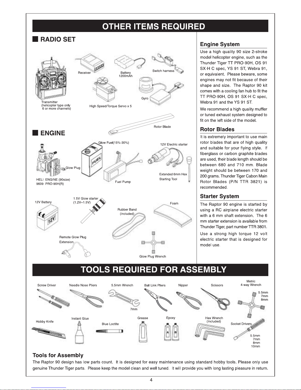
Page 4
Page 5
Page 6
Page 7
6
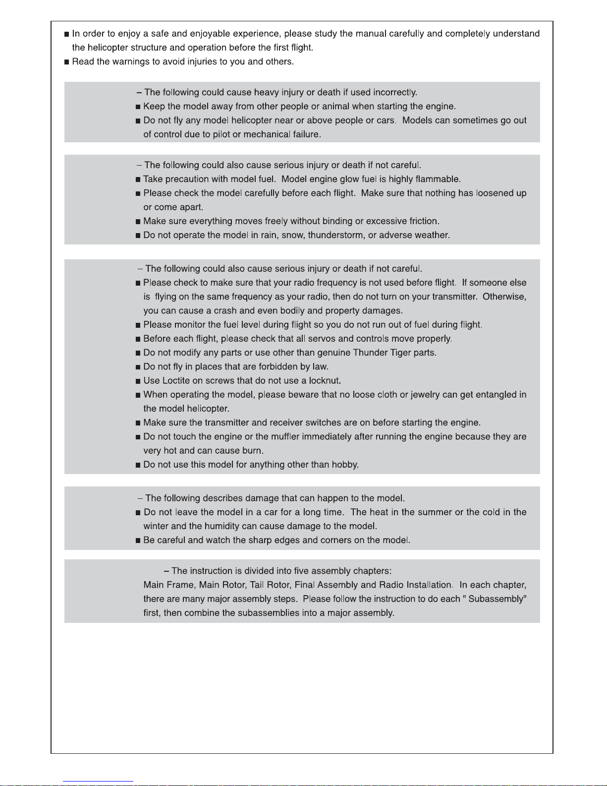
WARNING
WARNING
WARNING
WARNING
BUILDING HINT
Page 8
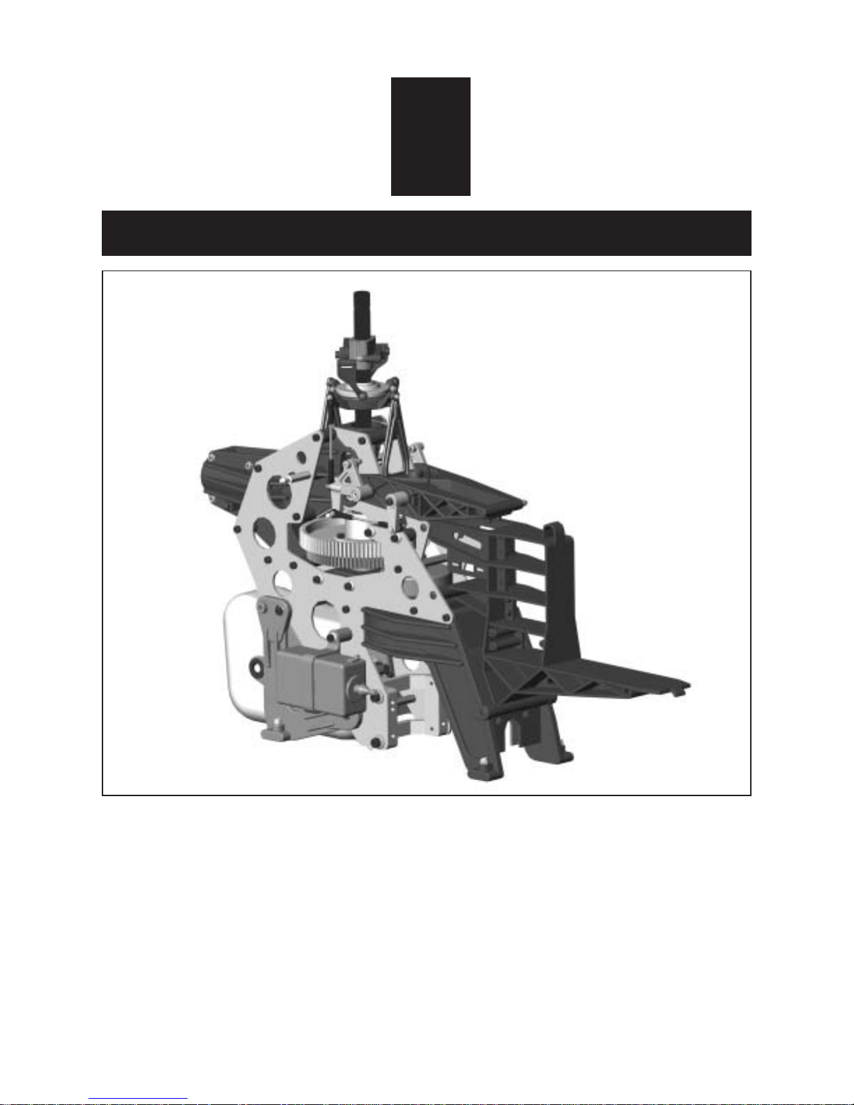
1
MAIN FRAME ASSEMBLY
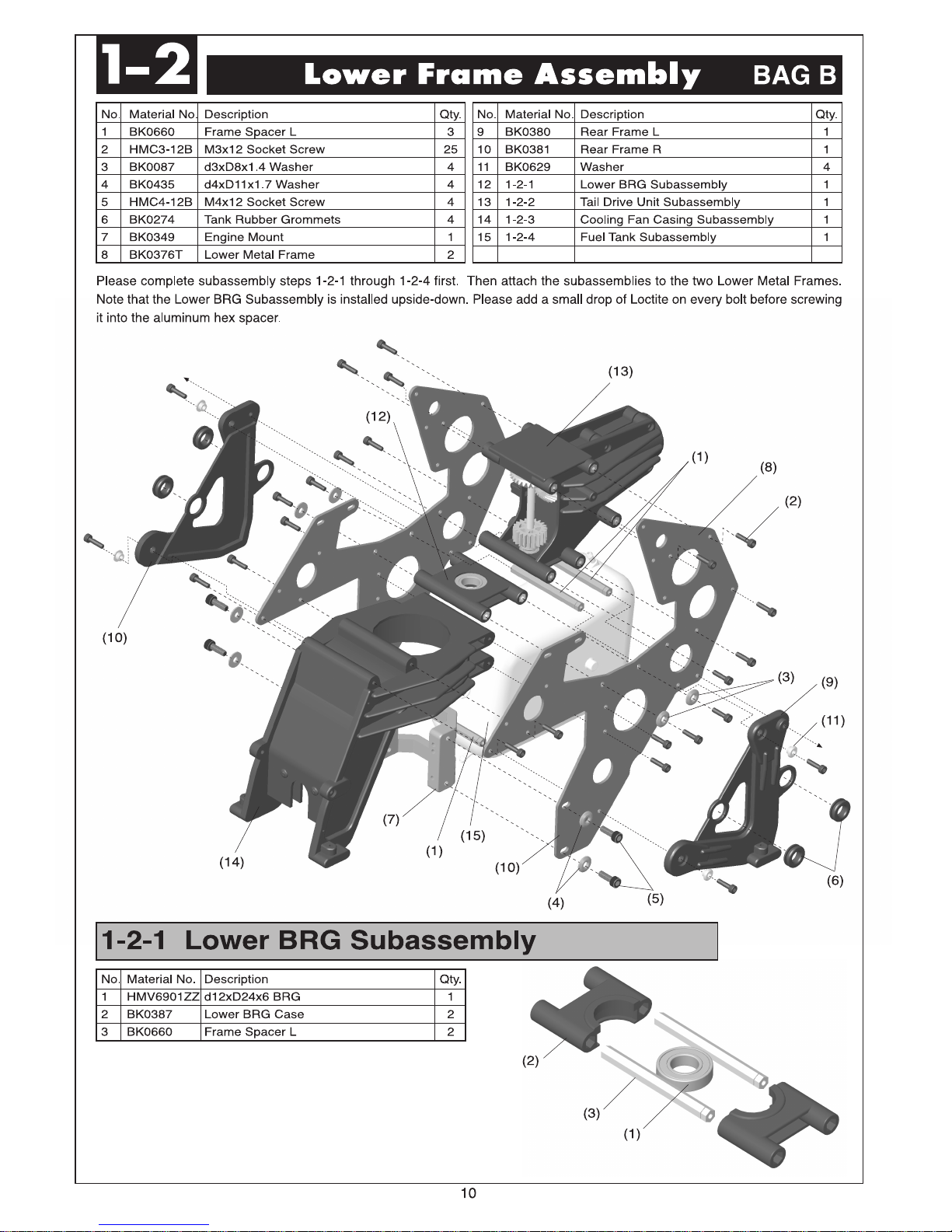
For the kit, parts are bagged according to each major assembly and are labeled "Bag A, Bag
B, etc." The heading for each assembly indicates which bag to open. As a good practice,
only open up the bag that you need for the particular assembly. Check the parts in that bag
against the parts list shown for each assembly as well as each sub-assembly to make sure
there are no missing parts. To prevent losing small hardware, please empty the small nuts
and bolts and parts into small plastic trays on your work table. At the end of each major
assembly, there should be no left over parts.
7
Page 9
Page 10
Page 11
Page 12
Page 13
Page 14
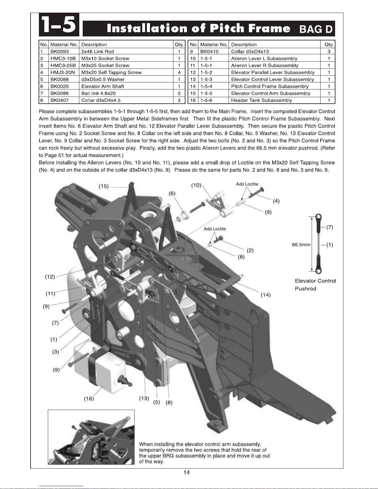
1-4
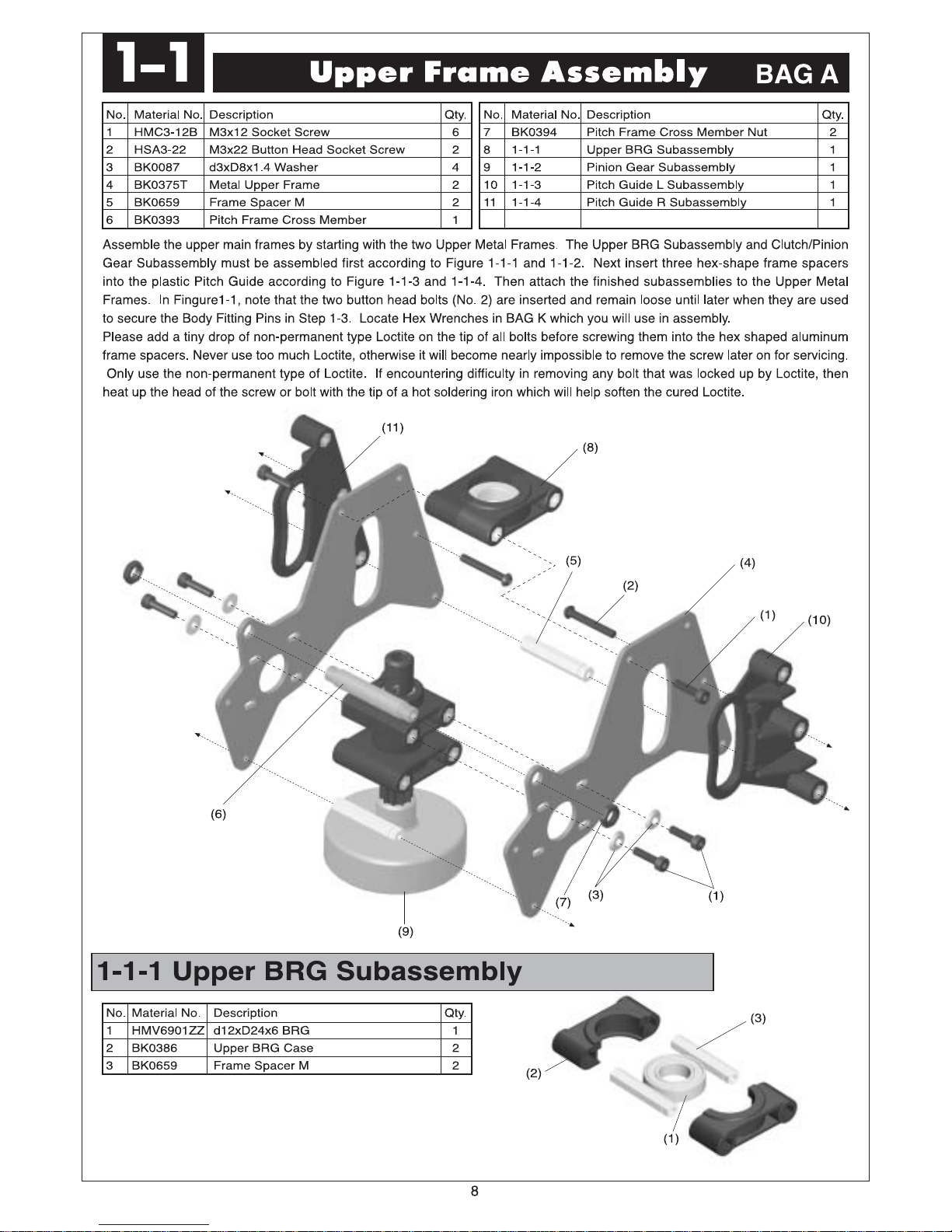
No. Material No. Description Qty.
1 BK0667 Servo Frame 1
2 HSE3-12B M3x12 Self-Tapping Screw 6
3 1-3 Main FrameAssembly 1
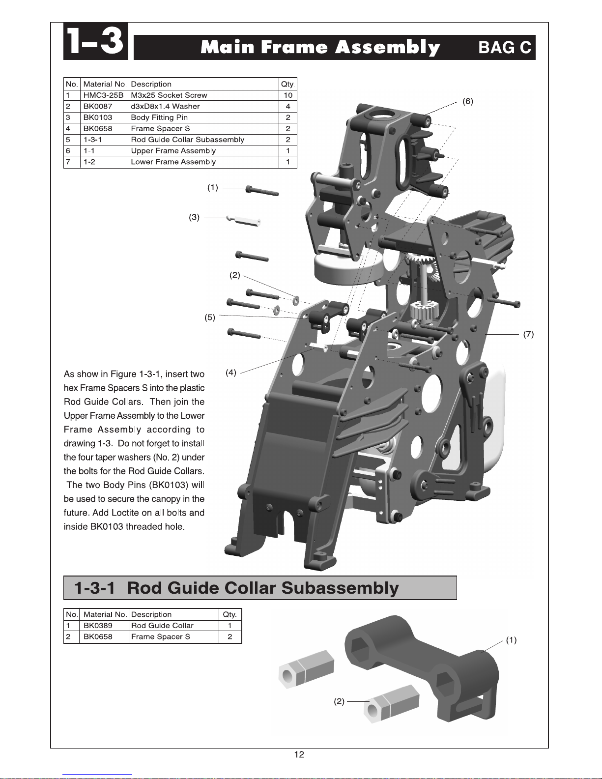
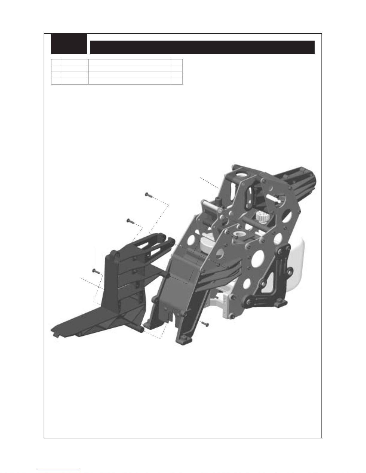
Install the one-piece servo frame using six self-tapping screws.
Do not use Loctite when attaching self-tapping screws to plastic
parts. Loctite is only for threading metal into metal parts.
Installation of Servo Frame
BAG C
(3)
(1)
(2)
13
Page 15
Page 16
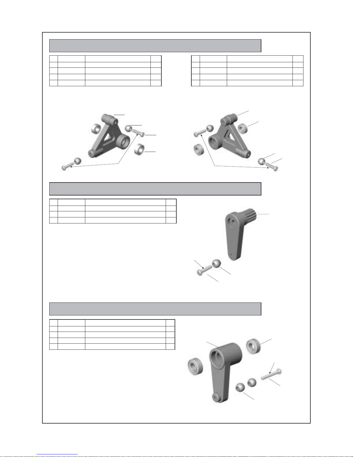
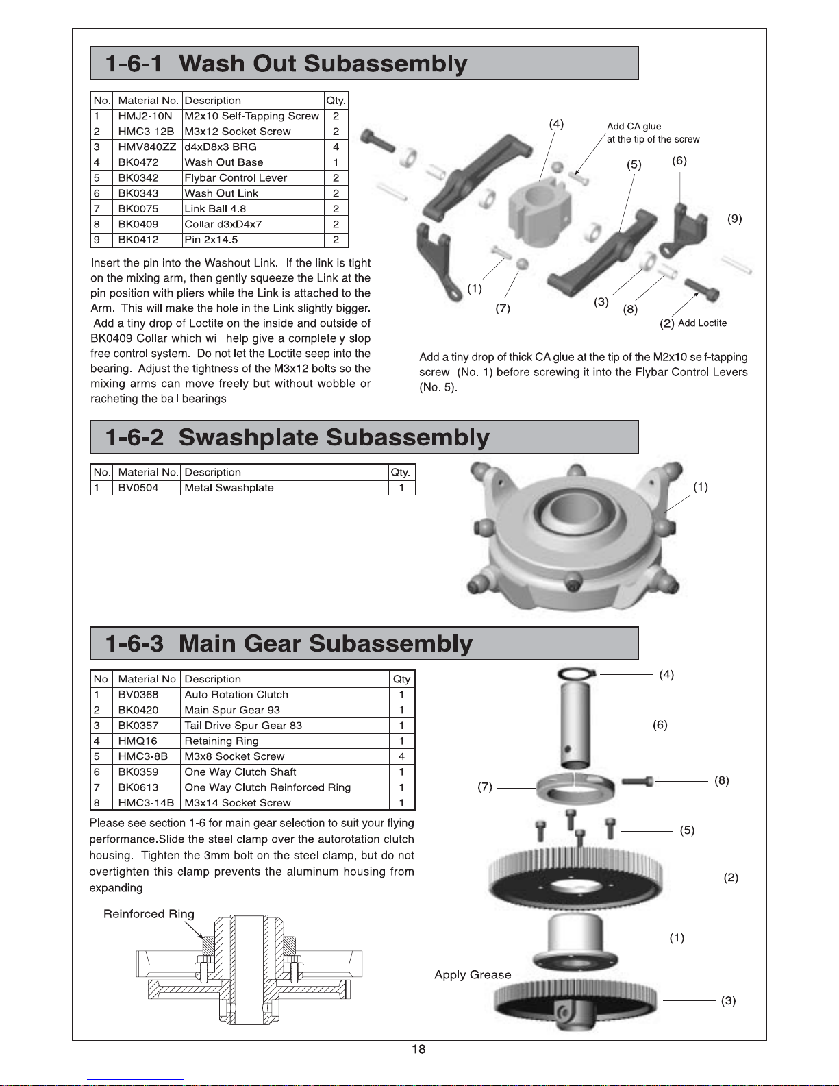
1-5-1 Aileron Lever Subassembly
No. Material No. Description Qty.
1 HMJ2-10N M2x10 Self-Tapping Screw 2
2 HMV840ZZ d4xD8x3 BRG 2
3 BK0340 Aileron ControlArm 1
4 BK0075 Link Ball 4.8 2
Add a tiny drop of thick CA glueat the tip of the M2x10
self-tapping screw (No. 1) before screwing itinto the
Aileron Levers.
(L)
(3)
(4)
Add CAglue
(1)
(2)
No. Material No. Description Qty.
1 HMJ2-10N M2x10 Self-Tapping Screw 2
2 HMV840ZZ d4xD8x3 BRG 2
3 BK0340 Aileron ControlArm 1
4 BK0075 Link Ball 4.8 2
(R)
Add CAglue
1-5-2 Elevator Parallel Lever Subassembly
No. Material No. Description Qty.
1 HMJ2-10N M2x10 Self-Tapping Screw 1
2 BK0337 Elevator Arm Parallel Lever 1
3 BK0075 Link Ball 4.8 1
(3)
(2)
(4)
(1)
(2)
Add CAglue
(3)
(1)
1-5-3 Elevator Control Lever Subassembly
No. Material No. Description Qty.
1 HMJ2-14N M2x14 Self-Tapping Screw 1
2 HMV840ZZ d4xD8x3 BRG 2
3 BK0338 Elevator Control Lever 1
4 BK0075 Link Ball 4.8 2
(3)
(2)
Add CAglue
(1)
(4)
15
Page 17
Page 18
Page 19
Page 20
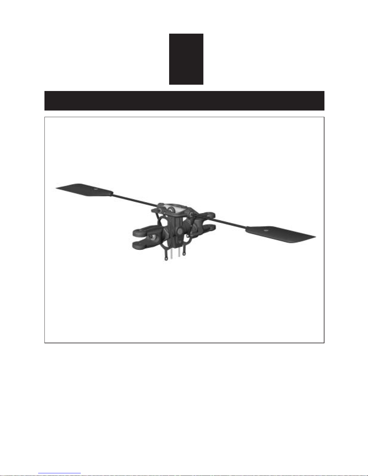
2
ROTOR HEAD ASSEMBLY
19
Page 21

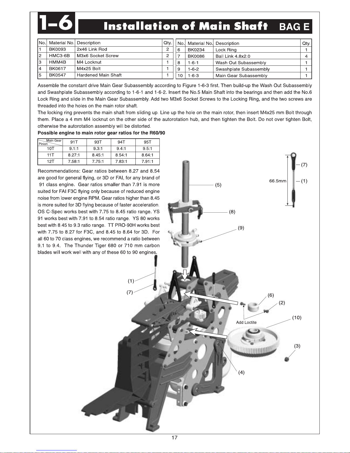
2-1
Rotor Head Assembly
BAG F
No. Material No. Description Qty.
1 BK0292 2.3x24 Link Rod 2
2 HMC3-10B M3x10 Socket Screw 2
3 HMV694ZZ d4xD11x4 BRG 2
4 BK0408 Collar d3xD4x5.5 2
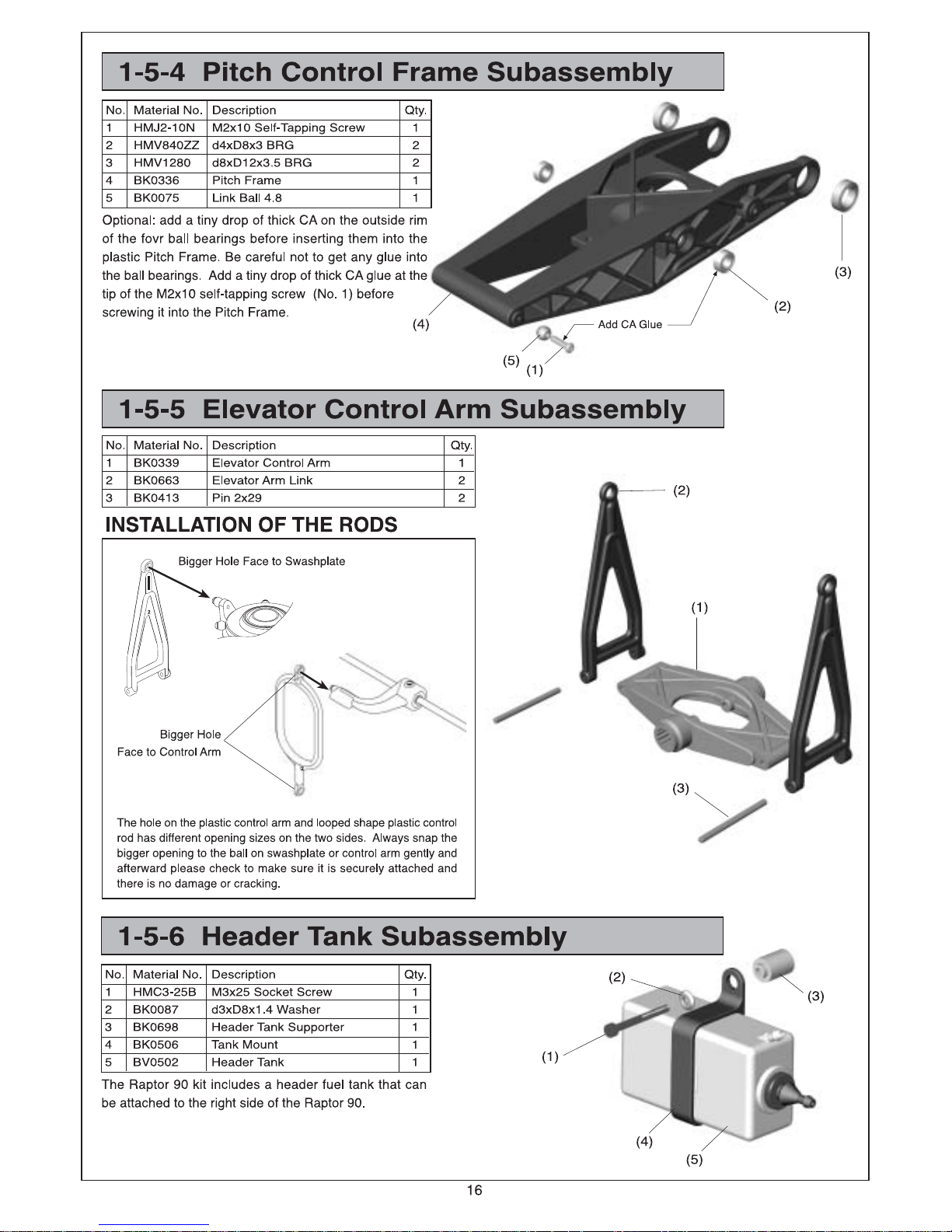
Make two pushrods for controlling blade pitch. The distance of 43 mm is measured between thecenter of two pushrod holes.
Attach the Seesaw Hub of the Control PaddleAssembly to the Main Rotor Head with No.2 Socket Screws, No. 3 Bearing.
Please add a small drop of Loctite along the entire length of the M3x10 Socket Screw (No.2 ) and on the outside of the collar
d3xD4x5.5(No.4).
Link the pushrod onto the Rotor Grip and Mixing Lever (See illustration in P.28)
No. Material No. Description Qty.
5 BK0086 Ball Link 4.8 4
6 2-1-1 Flybar Seesaw Subassembly 1
7 2-1-2 Main Rotor Hub Subassembly 1
(5)
(1)
43mm
(6)
(2)
(3)
(4)
(5)
(1)
(7)
20
Page 22

Page 23

Page 24

3
TAIL ASSEMBLY
23
Page 25

Page 26

Page 27

Page 28

Page 29

Page 30

Page 31

Page 32

No. Material No. Description Qty.
5 BK0087 d3xD8x1.4 Washer 2
6 3-1 Tail Assembly 1
7 4-3-1 Tail Support Subassembly 2
No. Material No. Description Qty.
1 HMM3B M3 Locknut 4
2 HSE3-12B M3x12 Self-Tapping Screw 2
3 HMC3-20B M3x20 Socket Screw 2
4 HMC3-25B M3x25 Socket Screw 4
Page 33

Page 34

No. Material No. Description Qty.
1 HML2 M2 Nut 4
2 HMF2-8N M2x8 Philip Machine Screw 4
3 BK0436 2.3x55 LinkRod 2
4 BK0438 2.3x88 LinkRod 1
5 HSE2614N 2.6x14 Self Tapping Screw 12
6 HME4-5B M4x5 Set Screw 2
No. Material No. Description Qty.
7 ***** Servo 5
8 BK0105 Rod Joint 1
9 BK0347 Tail Control Rod A (In BAG O) 1
10 BK0075 Link Ball 4.8 4
11 BK0086 BallLink 4.8x20 7
12 BK0104 Servo Mounting Plate 6
Page 35

Page 36

Page 37

Page 38

Page 39

38
SETTINGS
6
Page 40

Page 41

Page 42

Page 43

Page 44

43
Always operate or fly a model helicopter in a safe manner and away from crowd, or spectators,
or distractions.
Do not operate model helicopters in rainy or windy condition.
Check to make sure there is no radio interference before operating a model helicopter.
Make sure the transmitter and receiver batteries are fully charged before operation.
Make sure all controls operate properly before flight.
Model helicopter main and tail rotors operate at high rpm, therefore make sure nothing can come
into contact with the rotors during flight.
Use only model engine fuel. Do not use gasoline, kerosene, or any other substitute.
Model engine fuel is highly flammable.
Do not let model engine fuel get in contact with eyes. Do not intake model engine fuel.
Range check the radio before flying. The servos must operate properly with the transmitter
antenna collapsed and at 20 meters away.
The engine must be in the idle position before starting the engine.
Make sure the transmitter and receiver are turned on before starting the engine.
Always maintain a safe distance when operating a model helicopter.
Do not fly a model helicopter above people or cars.
Flying requires concentration. Operating a model helicopter for extended time can cause fatigue.
Please rest in between flights.
Do not touch the engine or muffler immediately after the engine was run, because they will be
extremely hot.
Warning (Items to watch out after flight)
Inspect the model helicopter thoroughly to make sure nothing is loosen or damaged.
Pump out the remaining fuel from the fuel tank.
Lubricate every moving part with oil to ensure a smooth operation in the future.
Warning (For Storage)
Keep the model in a cool, dry place. Avoid storage under direct sun light or near heat.
Add some engine after-run oil through the carburetor, then crank the engine by an electric starter.
This help to prevent the engine bearings from rusting. After-run oils are available from hobby
shops.
Please replace any damaged parts if they are discovered during maintenance.
Attention
Page 45

44
Control system check.
(1) The flybar and control paddles must tilt in the proper direction and smoothly through the whole range.
(2) The rotor shaft and flybar must be straight and not damaged.
(3) The swashplate must remain clean and tilts freely.
(4) When control input are given to tilt the swashplate, make sure none of the control arms and pushrods
show any binding.
(5) The two control paddles must be leveled and parallel to each other, and point in the correct direction.
(6) Check to make sure there is no radio interfence before operating the model helicopter.
(7) Make sure the transmitter and receiver are on and all controls operate properly before flight. Range
check the radio.
(8) The engine carburetor must be in the idle position before starting the engine. Please read the engine
instruction manual on how to properly adjust the engine. Set the carburetor main needle according to
the engine instruction. Depends on the fuel and glow plug used, the carburetor idle screw may require
fine adjustment of 1/4 to 1/2 turns away from the factory setting.
(9) Fuel up the tank, move the throttle stick to idle, and connect a specially designed glow plug battery to
the glow plug.
Preflight Checklist and Starting Procedure
œAlwaysgrab onthehelicopter
main rotor head when
starting the engine.
Otherwise, the main
rotor may start spinning
immediately after the
engine is started.
(10)Use a 12 volt model engine electric start
along witha6mmhexstarter extension
(sold separately) to start the engine.
Page 46

Flying Adjustments (1)
45
Tracking adjustment ... When the two main rotor blades are in track it means their blade tips
should follow the same path as they rotate.
(1) Rev up the motor until the helicopter becomes
light on its skids.
(2) When the two main rotor blades are in
track it means their blade tips should follow
the same path as they rotate, then it's ok.
(3)
When two blades are in track, the blade tips will
appear overlapped as one look at the rotor tip
path plane from the edge.
If the blades are out of track, then adjust
one of the pushrods that connects to the
main rotor blade pitch arm.
Redo steps (1) to (3) until
the blades are tracking
properly.
In hover, the main blades should be
around 5.5 to 6 degrees in pitch.
out of track
in track
increase
throttle gently
and not too
much
Page 47

46
Flying Adjustments (2)
Trimming: All helicopters are inherently unstable. But when a helicopter is properly trimmed, it
will not drift away or yaw by itself quickly. Use the following procedure to trim your
helicopter.
(1) If the helicopter nose starts to yaw left or right,
then
use the transmitter trim to compensate:
(3) If the helicopter noses down or up, then:
yaw right
yaw left
(A) situation: move to (b)
(B) situation: move to (a)
(2) If the helicopter rolls to left or right, then:
rolls right
rolls left
(C) situation: move to (d)
(d) situation: move to (c)
Noses down
Noses up
(E) situation: move to (f)
(F) situation: move to (e)
Page 48

47
Hover Training (1)
Hovering is when the helicopter is floating in a stationary position in the air. Hovering is the
fundamental manuever to learn first. Here is the procedure to practice hovering:
(1) Make sure there is no spectator anywhere
near the model helicopter. You, the pilot,
should stand at least 10 meters (30 feet)
behind and slightly to the side of the model
helicopter.
(3) Increase the throttle/collective to lift the model helicopter skids off the
ground to no more than 10 cm(4 inches). Initially, it will be very difficult
to control the model to prevent it from moving. For a beginner it will
also be difficult to determine whether the helicopter is in trim or not.
But with repeated practice close to the ground you will develop a feel
for the controls. It is recommended to let a more experienced model
helicopter pilot trim out your new model before you attempt to learn
to hover.
(2) Prior to lifting off, while the main rotor is spinning and the helicopter is
on the ground, check the main rotor fore/aft and left/right cyclic to make
sure the main rotor is tilting in the correct direction according to your
cyclic command. Move the tail rotor control stick to make sure the
helicopter nose will swing in the desired direction accordingly.
Page 49

48
(4) It will take a few hours of hover practice with the helicopter skids at 10 to 20 cm (4-8 inches)
off the ground in order to comfortably control the model.
Do not try to lift the model to more than 10 to 20 cm(4-8 inches) in the beginning because
then the model may tip over readily when the beginner panics and an incorrect command is
given. Once you can keep the model at one place, then it is time to slowly increase the height
a few centimeters (inches) in each flight. Soon, you will be able to hover the helicopter
confidently at few feet high. Beginners should always practice hovering close to the ground
because in an emergency panic, throttle and collective can be reduced rapidly without causing
a large drop or damage to the model. If the model was hovering at beyond one meter(3 feet)
altitude, then always descend slowly. A panic drop can damage the helicopter.
(5) Always stand behind the model helicopter when learning how to hover because then you
can watch the nose of the helicopter, and a left tail rotor command will yaw the helicopter
nose to the left, and a right command will yaw to the right. Similarly, a left cyclic command
will cause the helicopter to translate left. After you can comfortably hover the model at one
meter high without drifting, then start practice hovering while standing to either side of the
model. Eventually, you need to be comfortable
at hovering the model from any orientation,
including with the helicopter nose pointing at
you, this is challenging because all control
directions are seem backward.
(6) Once you can confidently hover a model helicopter at any altitude and at any orientation,
then congratulate yourself because you have mastered 80% of the fundamental control
movements of a helicopter.
Page 50

Forward Flight Training
After mastering hovering flight:
(1) Start practicing moving the helicopter laterally to the left or right slowly from a 1.5 meter (60
inches) high hover. This is the beginning exercise of translational flight.
(2) After a few hours of practicing step (1) and you are comfortable with translational movement,
start using some tail rotor control so the helicopter nose will point slightly to the left or right
as you fly it to the left or right. Eventually, this pattern will become a figure-eight in front of
you. Please visualize these movements in your mind.
hovering at 1-1.5 meter
49
Page 51

50
[1]The engine will not start.
* The engine starting shaft will not turn:
The engine may be flooded with too much fuel. Please remove the glow plug first, then turn the engine
with the electric starter until the excess fuel spits out of the glow plug hole.
* The engine turns when the electric starter is applied, but the engine will not start:
(1) Is the glow plug working? Remove the glow plug and does the platinum coil glow red when a 1.5
volt battery is applied to the plug? The glow plug battery may be weak and old.
(2) Is the carburetor needle properly set? Please refer to the engine instruction manual for the proper
needle setting.
(3) Does the throttle control arm move properly and in the correct direction according to your transmitter
command?
* Engine will start, but quits immediately.
(1) Use the transmitter to increase the throttle carburetor slightly.
(2) Try a new or different type of glow plug. There are different types of glow plugs on the market for
different types of fuel and operating conditions. Seek the advice of experienced fliers and also
experiment with different types of glow plugs until you find the one that suits your operating condition
the best.
*Engine runs, but the helicopter will not lift off.
(1) Check the main rotor blade pitch angle, they should be set at 5.5 to 6 degrees when the transmitter
throttle/collective stick is at the center position.
(2) Does the engine throttle arm move properly? The carburetor opening should be fully open when
the transmitter throttle/collective stick is moved up. The carburetor opening should be nearly closed
when the transmitter throttle/collective stick is moved down. And the opening should be completely
closed when the transmitter throttle/collective stick is moved down and the throttle trim is also moved
down.
(3) The carburetor needle is not set properly. Close the needle (turn it clockwise) all the way, then
open the needle (turn it counter clockwise) 1 and 1/2 turns and try again. If the model still will not
lift, then the engine maybe running too rich. The symptom is the engine exhaust has a lot of smoke
and the engine coughs and wants to quit when the transmitter throttle/collective stick is moved up,
then close the needle 1/8 turn at a time, until the model will lift off. Do not turn the needle too far
inward, that will make the engine run too lean and over-heat and damage the engine.
[2] Helicopter problems.
* The helicopter shakes.
(1) Is the blade spindle bent?
(2) Is the flybar bent?
(3) Is the main rotor shaft bent?
(4) Are the two control paddles mounted at the same distance from the rotor shaft, and the paddles
are parallel to each other, and in the proper direction?
(5) Is the tail rotor shaft bent? The tail rotor blades mounted properly or damaged?
(6) Are the main rotor blades damaged or mounted in the proper orientation? The blade may require
additional balancing. The blade balance can be checked by removing both blades and then use
one of the 5mm blade bolt and nut to hold the two blades together like a teeter totter. Then, hold
the blade bolt with your thumb and index finger. The two blades should teeter and remain in a
level position. If not, then add some tape to the lighter blade near the blade tip until the two blades
teeter in a level position. Hobby shops also sell blade balancers that are designed solely for balancing
model helicopter blades.
The model helicopter should be thoroughly inspected after each flying session.
(1) Check every screw and bolt to make sure none has loosened due to vibration.
(2) Check every rotating and movable part to ensure they still move smoothly and normally.
(3) Clean off the exhaust residue from the muffler, engine, and helicopter.
(4) Check all movable parts, such as gears, ball links, belt, etc. for unusual wear.
Trouble Shooting
After Flight Checklist
Page 52

51
In the event the model has crashed.
Inspect the flybar, rotor shaft and the blade spindle to make sure they are not bent at all. If any item is damaged, it
must be replaced by a new part to ensure safe operation. Do not glue any broken or damaged plastic part. Do not
repair broken rotor blades. Always inspect the following items immediately:
(a).Engine starting shaft.
(b).All the gears.
(c).Main shaft, flybar and blade feathering spindle.
(d).Tail boom and supports for cracks.
(e).Drive shaft for the tail rotor.
(f). Vertical and horizontal fins.
(g).Tail rotor shaft and control system.
(h).Main and tail rotor blades.
(i). Main frame.
Page 53

Page 54

Page 55

Page 56

Page 57

Page 58

Page 59

PV0041 BALL LINK BK0086 Ball Link 4.8x20 12
PV0046 ELEVATORARM ,BRG HMV1280 d8xD12x3 BRG 2 1-5-4
PV0048
BRG:PITCH FRAME &ROTOR HUB SEESAW
HMV840ZZ d4xD8x3 BRG 2
4830 / LEVER& PITCH ARM4870
PV0050 BRG:FEATHERING 4830/TAIL SHAFT HMV1350 d5xD13x4BRG 2 3-1-1
PV0052 TAILSLIDER BRG HMV1060 d6xD10x3 BRG 2 3-1-2
PV0054 SERVO MOUNTING PLATE BK0104 Sever Mounting Plate 10 5-1, 5-2
PV0058 LINK BALL BK0075 Link Ball 4.5 12
PV0062 BODY MOUNT RUBBER GROMMENTS BK0102 d3xD6x11 RUBBERGrommet 5 5-4-1
PV0120 MAIN ROTOR GRIP BK0075 Link Ball 4.8 2 2-1-2
BK0319 Main Rotor Pitch Housing 2 2-1-2
HMJ2-10N M2X10 Self-Tapping Screw 2 2-1-2
PV0123 MIXING LEVER BK0324 Mixing Lever 2 2-1-1
BK0075 Link Ball 4.8 4 2-1-1
BK0410 Collar d3xD4x13 2 2-1-1
HMC3-18B M3x18 Socket Screw 2 2-1-1
BK0088 d3xD5x0.5 Washer 2 2-1-1
HMJ2-10N HMJ2-10N 4 2-1-1
PV0124 FLYBAR CONTROL ROD BK0344 Flybar Control Rod 2 2-1-1
PV0125 THRUST WASHER BK0325 Thrust Collar 2 2-1-2
PV0126 SPINDLE BK0326 Spindle 1 2-1-2
BK0477 Washer 2 2-1-2
HMC4-10B M4x10 Socket Screw 2 2-1-2
PV0131 ELEVATORARM BK0020 Elevator Arm Shaft 1 1-5
BK0075 Link Ball 4.8 1 1-5-2
BK0335 Elevator Arm Link 2 1-5-5
BK0337 Elevator Arm ParallelLever 1 1-5-2
BK0339 Elevator Control Arm 1 1-5-5
BK0413 Pin 2x29 2 1-5-5
HMJ2-8N M2x8 Self-Tapping Screw 1 1-5-2
HMJ3-20N M3x20 Self-Tapping Screw 2 1-5
PV0132 PITCH CONTROLARM BK0075 Link Ball 4.8 2 1-5-4
BK0336 Pitch Frame 1 1-5-4
BK0407 Collar d3xD4x13 1 1-5
HMC3-10B Elevator Control Lever 1 1-5
HMC3-25B M2x14 Self-TappingScrew 1 1-5
HMJ2-10N M2x10 Sefl-Tapping Screw 1 1-5-2
PV0133 ELEVATOR LEVER BK0075 Link Ball 4.8 2 1-5-3
BK0088 d3xD5x0.5 Washer 1 1-5
BK0410 Collar d3xD4x13 1 1-5
BK0338 Elevator Control Lever 1 1-5-3
HMJ2-14N M2x14 Self-Tapping Screw 1 1-5-3
PV0134 AILERON LEVER BK0075 Link Ball 4.8 4 1-5-1
BK0340 Aileron Control Arm 2 1-5-1
BK0410 Collar d3xD4x13 2 1-5-1
HMJ2-10N M2x10 Sefl-Tapping Screw 4 1-5-1
HMJ3-20N M3x20 Self-Tapping Screw 2 1-5
PV0135 TAILPITCH CONTROL LEVER BK0075 Link Ball 4.8 1 3-1-1
BK0076 Collar d3xD4x10 1 3-1-1
BK0088 d3xD5x0.5 Washer 1 3-1-1
BK0346 Tail Pitch Control Lever 1 3-1-1
HMJ2-8N M2x8 Self-Tapping Screw 1 3-1-1
HMJ3-20N M3x20 Self-Tapping Screw 1 3-1-1
PV0137 MAIN SHAFT LOCKRING BK0234 Lock Ring 1 1-6
HMC3-6B M3x6Socket Screw 2 1-6
PV0139 ONE WAY CLUTCH SHAFT BK0359 One Way Clutch Shaft 1 1-6-3
HMC4-25B M4x25 Socket Screw 1 1-6-3
HMM4B M4 Locknut 1 1-6-3
HMQ16 Retaining Ring 1 1-6-3
PV0140 TAILDRIVE GEAR SET BK0362 Tail Drive Bevel Gear A 1 1-2-2
BK0363 Tail Drive Bevel Gear B 1 1-2-2
BK0364 Tail Drive Pinion 1 1-2-2
BK0414 Pin 2x12 2 1-2-2
HME3-4B M3x4 Set Screw 2 1-2-2
No. NAME Parts No. Parts Name quantity Reference
Assembly Step
58
Page 60

59
PV0141 ENGINE MOUNT BK0349 Engine Mount 1 1-2
BK0435 d4xD11x1.7 Washer 4 1-2
HMC4-12B M4x12 Socket Screw 4 1-2
HMC4-18B M4x18 Socket Screw 4 4-2
PV0147 TAILCASE BK0370 Tail Case L 1 3-1-1
BK0371 Tail Case R 1 3-1-1
HMC3-10B M3x10 Socket Screw 3 3-1-1
HMM3B M3 Locket 3 3-1-1
PV0148 TAILROTOR GRIP BK0302-1 Tail Pitch Housing A 2 3-1-2
BK0303-1 Tail pitchHousing B 2 3-1-2
HMC26-10B M2.6x10 Socket Screw 4 3-1-2
HMC3-14B M3x14 Socket Screw 2 3-1-2
HMM26B M2.6 Locknut 4 3-1-2
HMM3B M3 Locknut 2 3-1-2
PV0149 TAILBEVEL GEAR BK0372 Tail Input BevelGear 1 3-1-1
BK0373 Tail Output Bevel Gear 1 3-1-1
BK0414 Pin 2x12 1 3-1-1
HME3-4B M3x4 Set Screw 1 3-1-1
PV0150 TAILROTOR SHAFT BK0374 Tail Shaft 1 3-1-2
BK0414 Pin 2x12 1 3-1-2
HME3-4B M3x4 Set Screw 1 3-1-2
PV0151 TAILROTOR HUB BK0307 Tail Rotor Hub 1 3-1-2
HME3-18B M3x18 Set Screw 2 3-1-2
HMM3B M3 Locknut 2 3-1-2
PV0154 MAIN SHAFT LOWERBRG CASE BK0387 Lower BRGCase 2 1-2-1
PV0155 PITCH GUIDE COLLAR SET BK0384 Pitch Guide Collar L 1 1-2-1
BK0385 Pitch Guide Collar R 1 1-2-1
PV0157 REAR FRAME SET BK0380 Rear Frame L 1 1-2
BK0381 Rear Frame R 1 1-2
BK0629 Washer 4 1-2
PV0158 TAILBOOM BRACKET BK0382 TailBoom Bracket L 1 1-2-2
BK0383 Tail Boom Bracket R 1 1-2-2
PV0162 FLYBAR PADDLE SET BK0406 Paddle Root 2 2-1-1
BK0416 Paddle Stopper 2 2-1-1
BK0432 Flybar Paddle 2 2-1-1
HME4-3B M4x3 Set Screw 4 2-1-1
PV0163 TAILROTOR BLADE BK0404 Tail Rotor Blade 2 3-1
PV0164 TAILFIN BK0399 Vertical Fin 1 3-1
BK0400 Stabilizer Fin 1 3-1
BK0401 Stabilizer Fin Bracket 1 3-1
HMC3-30B M3x30 Socket Screw 2 3-1
HMM3B M3 Locknut 2 3-1
HSE3-12B M3x12 Self-Tapping Screw 2 3-1
PV0169 LINKAGE ROD BK0093 2x46 Link Rod 3 1-5
BK0292 2.3x24 Link Rod 2 2-1
BK0318 2.3x95 Link Rod 2 4-1
PV0170 MAIN SHAFT BRG HMV6901ZZ d12xD24x6 BRG 2 1-1-1, 1-2-1
PV0171 BODY BK0098 Body Clip A 1 5-4-1
BK0099 Body Clip B 1 5-4-1
BK0102 d3xD6x11 RUBBER Grommet 2 5-4-1
BK0428 Canopy 1 5-4-1
BK0429 Body 1 5-4-1
HMJ2-6B M2x6 Self-Tapping Screw 8 5-4-1
HSE3-12B M3x12 Self-Tapping Screw 2 5-4-1
PV0172 THRUST BRG HMX0816 d8xD16x5Thrust Bearing 2 2-1-2
PV0174 FLYBAR SEESAW BRG HMV694ZZ d4xD11x4 BRG 2 2-1-1
PV0175 FEATHERING BRG HMV1680 d8xD16x5 BRG 2 2-1-2
PV0176 TAILPITCH CONTROL LEVERBRG HMV740ZZ d4xD7x2.5 BRG 2 3-1-1
PV0177 ROTOR BOLT BK0446 Rotor Bolt 2 5-5
HMM5Z M5 Locknut 2 5-5
PV0182 CLUTCH BELL BRG HMV1360Z d6xD13x5 BRG 2 1-1-2
PV0183 BODY RETAINING SET BK0103 Body FittingPin 2 5-4-1
HSA3-22 M3x22 Button HeadSocket Screw 2 5-4-1
PV0184 FLYBAR SEESAW BK0322 Flybar SeesawHub 1 2-1-1
No. NAME Parts No. Parts Name quantity Reference
Assembly Step
Page 61

60
BK0408 Collar d3xD4x5.5 2 2-1
HMC3-10B M3x10 Socket Screw 2 2-1
PV0186 MAIN SPUR GEAR 93T(STD) BK0420 Main Spur Gear 93T 1 1-6-3
PV0188 MAIN SPUR GEAR 95T(OPT) BK0431 Main Spur Gear 95T 1 1-6-3
PV0189 MAIN SPUT GEAR94T(OPT) BK0421 Main Spur Gear 94T 1 1-6-3
PV0190 TAILDRIVE SPUR GEAR BK0357 Tail Drive Spur Gear 83T 1 1-6-3
HMC4-25B M4x25 Socket Screw 1 1-6-3
HMM4B M4 Locknut 1 1-6-3
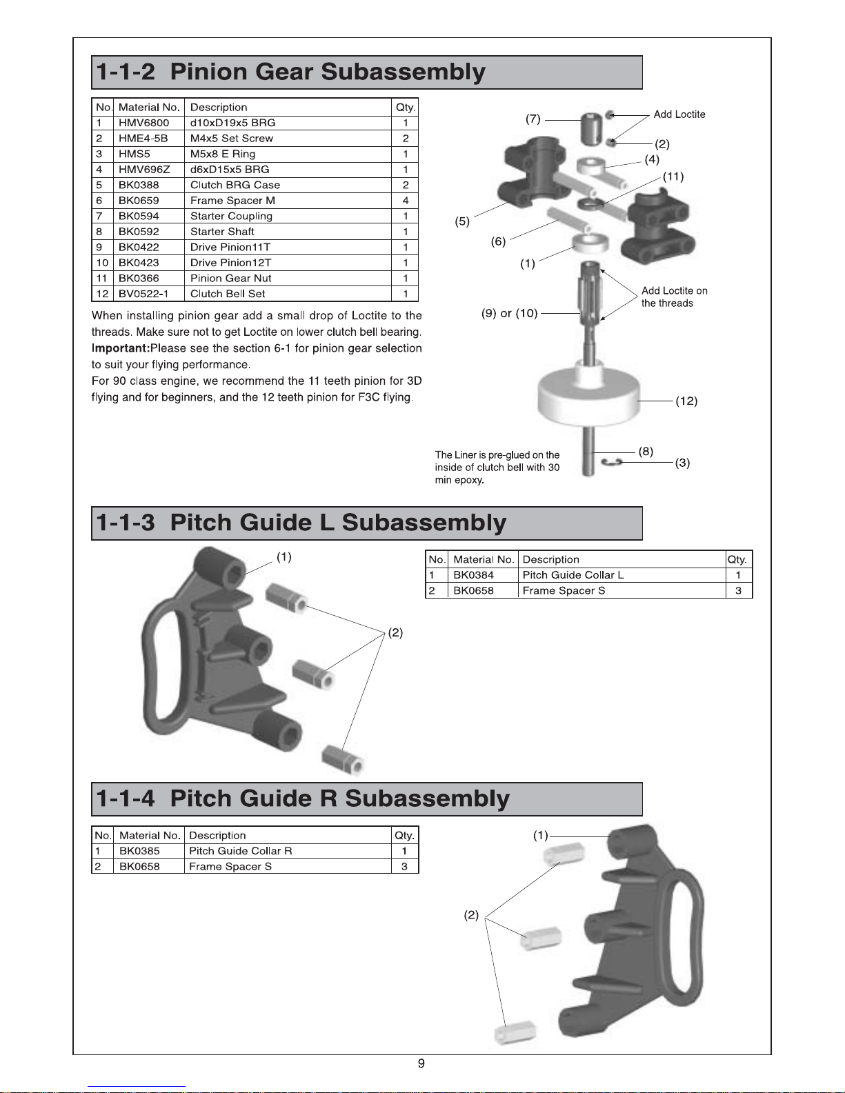
PV0191 PINION GEAR 10T(OPT) BK0355 Drive Pinion10T 1 1-1-2
BK0366 Pinion Gear Nut 1 1-1-2
PV0192 PINION GEAR 11T(STD) BK0422 Drive Pinion 11T 1 1-1-2
BK0366 Pinion Gear Nut 1 1-1-2
PV0193 PINION GEAR 12T(STD) BK0423 Drive Pinion 12T 1 1-1-2
BK0366 Pinion Gear Nut 1 1-1-2
PV0195 TAILDRIVE SHAFT BRG BV0423 Tail Drive Shaft BRG 1 3-1-3
PV0197 TAILDRIVE SHAFT BEVELGEAR BRG HMV6701Z d12xD18x4 BRG 2 3-1-1
PV0198 COOLING FANASSY BV0380 Cooling Fan Assy 1 4-2-1
PV0200 TAILROTOR BRG HMV1050 d5xD10x4 BRG 4 3-1-2
PV0203 STARTERSHAFT BRG HMV696Z d6xD15x5 BRG 2 1-1-2
PV0204 CLUTCH LINER BK0354 Clutch l iner 1 1-1-2
PV0206 CANOPY BK0428 Canopy 1 5-4-1
HMJ2-6B M2x6 Self-Tapping Screw 8 5-4-1
PV0208 FUEL TANK RUBBER GROMMENT BK0274 Tank Rubber Grommet 4 1-2
PV0209 WASHER,d4xD11xt1.7 BK0435 d4xD11x1.7 Washer 4
PV0210 WASHER,d3xD8xt1.4 BK0087 d3xD8x1.4 Washer 16
PV0211 SOCKET SCREW,M2.6x10 HMC2610B M2.6x10 Socket Screw 20
PV0212 SOCKET SCREW,M3x10 HMC3-10B M3x10 Socket Screw 20
PV0213 SOCKET SCREW,M3x12 HMC3-12B M3x12 Socket Screw 20
PV0214 SOCKET SCREW,M3x14 HMC3-14B M3x14 Socket Screw 20
PV0215 SOCKET SCREW,M3x18 HMC3-18B M3x18 Scket Screw 20
PV0216 SOCKET SCREW,M3x25 HMC3-25B M3x25 Scket Screw 20
PV0217 SOCKET SCREW,M3*28 HMC3-28B M3x28 Scket Screw 20
PV0218 SOCKET SCREW,M3x8 HMC3-8B M3x8 ScketScrew 20
PV0219 SOCKET SCREW,M4x10 HMC4-10B M4x10 Scket Screw 20
PV0220 SOCKET SCREW,M4x12 HMC4-12B M4x12 Scket Screw 20
PV0221 SOCKET SCREW,M4x18 HMC4-18B M4x18 Scket Screw 20
PV0222 SOCKET SCREW,M4x25 HMC4-25B M4x25 Scket Screw 20
PV0223 SOCKET SCREW,M4x8 HMC4-8B M4x8 ScketScrew 20
PV0224 SET SCREW,M3x18 HME3-18B M3x18 Set Screw 20
PV0225 SET SCREW,M3x4 HME3-4B M3x4 Set Screw 20
PV0226 SET SCREW,M4x3 HME4-3B M4x3 Set Screw 20
PV0227 SET SCREW,M4x5 HME4-5B M4x5 Set Screw 20
PV0228 PHILIP MACHINE SCREW,M2X8 HMF2-8N M2x8 Philip Machine Screw 20
PV0229 SELF-TAPPING SCREW,M2x10 HMJ2-10N M2x10 Sefl-Tapping Screw 20
PV0230 SELF-TAPPING SCREW,M2x14 HMJ2-14N M2x14 Self-Tapping Screw 20
PV0231 SELF-TAPPING SCREW,M2x6 HMJ2-6B M2x6 Self-Tapping Screw 20
PV0232 SELF-TAPPING SCREW,M2x8 HMJ2-8N M2x8 Self-Tapping Screw 20
PV0233 SELF-TAPPING SCREW,M3x20 HMJ3-20N M3x20 Self-Tapping Screw 20
PV0234 Nut,M2 HML2 M2 Nut 20
PV0235 LOCK NUT,M2.6 HMM26B M2.6 Locknut 20
PV0236 LOCK NUT,M3 HMM3B M3 Locknut 20
PV0237 LOCK NUT,M4 HMM4B M4 Locknut 20
PV0238 LOCK NUT,M5 HMM5Z M5 Locknut 10
PV0239 BODY CLIP 4830/4870 BK0098 Body ClipA 1 5-4-1
BK0099 Body Clip B 1 5-4-1
HSE3-12B M3x12 Self-Tapping Screw 2 5-4-1
PV0240 SERVO LINK ROD BK0436 2.5x55 Link Rod 3 5-1
BK0095 2.3x76 Link Rod 1 5-2
BK0438 2.3x88 Link Rod 1 5-1
PV0241 ROD GUIDE COLLAR BK0389 Rod Guide Collar 2 1-3-1
PV0242 MAIN SHAFT UPPERBRG CASE BK0386 Upper BRG Case 2 1-1-1
PV0243 CLUTCH BRG CASE BK0388 Clutch BRG Case 2 1-1-2
PV0244 PINION BRG HMV6800 d10xD19x5 BRG 2 1-1-2
PV0245 WASH OUTLINK BK0343 WashOut Link 2 1-6-1
No. NAME Parts No. Parts Name quantity Reference
Assembly Step
Page 62

61
PV0246 TAILDRIVE GEAR SHAFT BK0365 Tail DriveGear Shaft 1 1-2-2
BK0414 Pin 2X12 2 1-2-2
HME3-4B M3x4 Set Screw 2 1-2-2
PV0247 ELEVATORARM LINK BK0335 ElevatorArm Link 2 1-5-5
PV0248 PITCH ARMCROSS MEMBER BK0393 Pitch Frame CrossMember 1 1-1
BK0394 Pitch Frame Cross Member Nut 2 1-1
PV0251 FUEL PLUG BK0445 Fuel Plug 3 1-2-4
PV0253 ANTENNA PIPE4830/4870 BE1052 Antenna Pipe 2 5-3
PV0254 INSTALLATION SET BK0106 TwoTouchTape 2
BK0109 Rubber Band 5x320xT1 2
HNI15 Hex Wrench 1.5m/m 1
HNI2 HEx Wrench 2m/m 1
HNI25 HEx Wrench 2.5m/m 1
HNI3 HEx Wrench 3m/m 1
HNI4 HEx Wrench 4m/m 1
HNJ-1 Tie Band2.5x100 3
PV0262 BODY SUPPORT BK0473 Budy Support 1 5-4-1
BK0474 Rubber Cap 2 5-4-1
HNLR6 R Pin 2 5-4-1
PV0267 LOCTITE #242 1
PV0268 LOCTITE #262 1
PV0269 PLASTIC GEAR GREASE 1
PV0270 THRUST BEARING GREASE 1
PV0284 METALSWASH PLATE BV0504 Metal Swash Plate 1 1-6-2
PV0298 91T MAIN SPURGEAR BK0356 Main Gear 91T 1 1-6-3
PV0310 FUEL TANK 550C.C BV0503 Fuel Tank 1 1-2-4
PV0322 HEAVYDUTY CLUTCH BV0521 Heavy Duty Clutch 1 1-1-2
PV0324 HEAVYDUTY CLUTCH LINER BK0523 H.D Clutch Linear 1 1-1-2
PV0350 MAIN SHAFT BK0547 Main Shaft 1 1-6
PV0351 ONE WAY CLUTCH REINFORCED RING BK0613 One WayClutch Reinforced Ring 1 1-6-3
HMC3-14B M3x14Socket Screw 1 1-6-3
PV0360 STARTERSHAFT BK0592 StarterShaft 1 1-1-2
HME4-5B M4x5 Set Screw 2 1-1-2
HMS5 M5x8 E Ring 1 1-1-2
PV0361 STARTERCOUPLING BK0594 Starter Couling 1 1-1-2
HME4-5B M4x5 Set Screw 2 1-1-2
PV0395 SUS FLYBAR ROD BK0640 SUS FlyBar Rod 1 2-1
PV0402 FLYBAR CONTROL ARM BK0655 Flybar ControlArm 2 2-1-1
BK0075 Link Ball 4.5 2 2-1-1
HMJ2-10N M2x10 Sefl-Tapping Screw 2 2-1-1
BK0323 Flybar Arm Bushing 2 2-1-1
HME4-6B M4x6 Set Screw 2 2-1-1
PV0403 MAIN ROTOR HUB BV0321 Main Rotor Hub 1 2-1-2
BK0330 Main Rotor Hub Pin 1 2-1-2
BK0617 Socket Screw 1 2-1-2
HMM4B M4 Locknut 1 2-1-2
PV0404 70 DUROMETER FLAPDAMPER BK0656 70 Durometer Flap Damper 2 2-1-2
PV0405 80 DUROMETER FLAPDAMPER BK0657 80 Durometer Flap Damper 2 2-1-2
PV0406 FLYBAR CONTROL LEVER SET BK0342 Flybar Control Lever 2 1-6-1
BK0075 Link Ball 4.8 2 1-6-1
BK0343 Wash Out Link 2 1-6-1
BK0409 Collar d3xD4x7 2 1-6-1
BK0412 Pin 2x14.5 2 1-6-1
HMC3-12B M3x12 Socket Screw 2 1-6-1
HMJ2-10N M2x10 Sefl-Tapping Screw 2 1-6-1
PV0407 TAILPITCH SLIDER BK0026 Tail Pitch Control Link 2 3-1-2
BK0027 Tail Pitch Control Slider 1 3-1-2
BK0075 Link Ball 4.5 1 3-1-2
BK0082 Collar d3xD3x4 2 3-1-2
HSE2-10B M2x10 Self-Tapping Screw 2 3-1-2
HMJ2-8N M2x8 Self-Tapping Screw 1 3-1-2
PV0408 HEAVYDUTY CLUTCH BELL BV0522-1 Heavy Duty ClutchBell Set 1 1-1-2
PV0409 ONE WAY CLUTCH BV0368 Autorotation Clutch 1 1-6-3
HMC3-8B M3x8 Socket Screw 4 1-6-3
No. NAME Parts No. Parts Name Quantity Reference
Assembly Step
Page 63

Page 64

Page 65

Page 66

 Loading...