

Page 1

ø1809
ø300
SPECIFICATION / 規格表
Description / 產品名稱
Item No. / 產品料號
Power / 動力
Rotor Head / 主旋翼頭型式
Length / 總長
Width / 總寬
Height / 總高
Main Rotor (Req’d)
主旋翼
Tail Rotor (Req’d)
尾旋翼
Main Gear / Pinion 主齒盤 / 驅動齒數
Gear Ratio (E:M:T) / 齒輪比
Full Equipped Weight w/o Battery
全配重量不含電池
Max. Battery on Board
電池最大承載量
Recommended Power Configuration
動力搭配建議
Length / 長度
Diameter / 迴轉直徑
Length / 長度
Diameter / 迴轉直徑
1490
RAPTOR E820
4793
Electric Motor
Flybarless
1490 mm / ( 58.66" )
221mm / ( 8.7" )
432 mm / ( 17.0" )
813 mm / ( 32" )
1809 mm / ( 71.2" )
115 mm / ( 4.52" )
300 mm / ( 11.8" )
111T (standard), 115T (option) / 11T, 12T
10.09 (11T) : 1 : 4.67
9.25 (12T) : 1 : 4.67
3670-gram
(129.5 oz)
215 x 62 x 105 mm (8.5 x 2.4 x 4.1”)
Battery: 14S (7S x 2) 5.0~6.0Ah
Battery C-rate: Above 30C
ESC:160~200A
Motor:380~480KV
Est. Rotor rpm:1900
No.4793
432
221
FEATURES / 特色
1. Latest fiberglass canopy design w/sleek scheme
2. Collective pitch range +/-15 degrees
3. Reinforced thicker rotor grip plate
4. Carbon tail boom support
5. Innovative quick calibration system
6. Lightened metal main shaft bearing blocks
7. 15mm hardened hollow steel main shaft
8. 2mm aerospace grade true carbon side frame
9. Ultra thick helical main gear 111T(115T OP) V.S. 11T/12T Pinion(8mm)
10. Lite yet rigid one-piece machined AL tail case
11. Precisely and heavy-duty tail rotor system
12. 8mm torque tube driven w/efficient helical bevel tail gear
13. Recommend approx. 400KV outrunner max. O.D. 64mm
14. Quick-release battery tray fits two 7 cells Lipo battery packs
15. Adjustable one-piece U type pinion bearing block w/motor mount(Applicable to a 8mm
diameter motor shaft)
16. Adjustable metal rudder servo mount for better precise tail control
17. Lightweight and rugged landing skid for low center of gravity
18. Easy to install tail rotor rod guide
19. Lightweight one-piece metal tail boom support bracket
20. Lengthened FBL rotor grip post for precisely cyclic pitch control
21. All metal servo horns and control arms assembly eliminate the need for upgrades
22. Optional carbon battery tray available
1. 原廠塗裝完成高彩度玻璃纖維機頭罩
2. 主旋翼攻角最大可達+-15度
3. 強化加厚型主旋翼轉座搖臂
4. 碳纖維尾管支撐架
5. 原創中立點快速校正系統
6. 輕量化主軸軸承座
7. 15mm熱處理強化主軸
8. 高強度2mm碳纖維側板
9. 超厚111T螺旋主齒盤(115T選配),並配置兩顆8mm馬達齒(11T與12T)
10. 一體成型輕量化高強度金屬尾座
11. 高精度全金屬尾旋翼系統
12. 8mm尾傳動軸並搭配高負載尾螺旋傘齒
13. 適用馬達外徑可達64mm,建議使用400KV以獲得充足動力
14. 原創電池快拆機構,可容納2組7CELLS鋰電池
15. 一體式U型馬達與驅動齒輪固定座(可適用8mm馬達軸)
16. 可調式尾舵伺服機固定座提供更精準的尾部控制性
17. 高強度輕量化低重心腳架組
18. 快拆式尾舵拉桿導環
19. 一體成型輕量化金屬尾管支撐固定座
20. 加長型主旋翼轉座支柱提供更精準的螺距控制
21. 配備金屬伺服機舵片及控制臂組,無需額外進行升級改裝
22. 可換裝碳纖維電池座(選配)
This radio control model is not a toy! Before beginning assembly, please read this
manual thoroughly.
INSTRUCTION MANUALINSTRUCTION MANUAL
The contents are subject to change without prior notice due to product improvements
and specification changes.
本產品為高性能模型非一般玩具,組裝與操作前請詳閱本產品說明書。
本套件所附之零件可能跟圖示有所差異。因產品後續之設計研發或功能不斷改善之原因,我們
組裝說明書
將保留產品規格變更權利,不再另行通知使用者。
JK6173
E820
3D
Page 2
Page 3
INTRODUCTION /
Thank you for purchasing the Thunder Tiger RAPTOR E820 R/C helicopter. This new helicopter is the
latest innovation by Thunder Tiger. It has the perfect combination of flying stability and the agility for 3D
flying. This helicopter is an excellent choice for flying enthusiasts like you. For convenient assembly and
safe operation of the helicopter, please read the instructions carefully. Retain the user manual in case you
need it for any information or reference.
感謝您購買雷虎科技RAPTOR E820直昇機產品,本項產品為雷虎科技全新開發機種,兼具高度穩定性與3D飛行特性
,是熱衷引擎直昇機的您不可錯過的選擇。請於使用本產品前詳盡閱讀使用手冊,以利於組裝工作順暢進行與安全操
控本產品。請妥善保存使用說明書,以利後續調整與維修參考用途。
簡介
CAUTION /
1. R/C models are not toys. This product is a high-precision flying machine. Possibilities of unexpected
crashes may occur due to electronic interference, incorrect operation, or poor mechanical maintenance.
Although it is a R/C model helicopter, the rotor blades rotate at high speeds, which may cause serious
damage, injury, or death if the model hits people or property. Therefore, extreme caution must be
exercised during operation.
2. Thunder Tiger ensures parts packaged in this product is of the highest quality. However, after assembly
and usage, parts damaged due to wear or misuse will not be replaced under any circumstances. If you
have any questions regarding its operation and repair, Thunder Tigers service agents are able to
provide free technical guidance.
3. This product is only recommended for users ages 16 and up. Because flying a R/C helicopter is difficult,
beginners must receive guidance and supervision from experienced pilots to minimize unexpected danger.
Practice in spacious areas, far away from obstacles such as buildings, trees, electrical towers, or crowds.
4. To decrease the cost of repair and maintenance for beginners, it is recommended to fly the helicopter
with a practice rack and to learn basic flying skills with a computer R/C flying simulator. (Crashes in
simulators are free to repair!)
1. 本項遙控直昇機產品並不是玩具,是一項結構精密、高專業度模型產品,如果未經正確組裝與操控,將可能對操控
者或其他人造成身體傷害。使用者必須了解,若未確實進行飛行前安全檢查或操控不當,而造成人員受傷或物體損
壞,使用者必須負起法律責任。
2. 本產品由高品質零組件組成,雷虎科技對於安裝過程、使用過後..等人為因素造成損壞事件不負損壞賠償之責。如您
需要本產品相關組裝、調整或其他協助,可與雷虎科技全省經銷商聯繫。
3. 本項產品禁止十六歲以下青少年與孩童使用。強烈建議初學者應取得技術支援後再進行飛行,以避免危險發生。請
於空曠地區操控本產品,並避免於建築物、樹木、電塔..等障礙物區域飛行。
4. 建議初學者可安裝練習架或透過電腦模擬軟體練習,可達到實際練習效果與符合經濟效益。
警告
AMA INFORMATION /
Operating a model helicopter requires a high degree of responsibility and skill. If you are a newcomer to the
hobby, it is best to seek help and guidance from accomplished model helicopter pilots. This will greatly
speed up the learning process and have you flying successfully in a reasonable amount of time. We also
would strongly urge you to join the Academy of Model Aeronautics, if you are in States. The AMA is a
non-profit organization that provides its members with a liability insurance plan as well as monthly magazine
entitled Model Aviation. All AMA charter aircraft clubs require all pilots to hold a current AMA sporting
license prior to operation of their models at club fields. For further information, contact the AMA at:
Academy of Model Aeronautics
5151 East Memorial Drive
Muncie, IN 47302
(317) 287-1256
http://www.modelaircraft.org
操控遙控直昇機對於飛行安全要求極高,需要高度的負責任態度配合,以及較高的操控技巧。如果您是一位初學者,
建議您必須向當地專業模型經銷商,或是遙控直昇機相關組織以及經驗豐富的玩家尋求相關協助,以獲得您所需要的
訊息以及專業知識。如此可有效協助您縮短學習的時間,更容易學會遙控直昇機的組裝、設定與操控技巧。
特別注意事項
-2-
Page 4
FLIGHT SAFETY CHECKLIST /
1. Make sure that the transmitter battery is fully charged before flying.
2. Make sure all control surfaces are operated properly before flying.
3. Do a range check of the radio before the first flight. The electronic equipment must operate properly
at a range of at least 5 meters (18 ft) even with the transmitter antenna collapsed.
4. Make sure there are no other pilots using the same radio frequency with yours and that there are no
other radio interference on your frequency.
5.
Be sure to turn on the transmitter first with the throttle stick in the idle position. Plug the battery into
the ESC last.
6. The main rotor and the tail rotor spin at very high RPM. Make sure nothing can come in contact with
the rotor blades during flight.
7. Always maintain a safe distance from the helicopter during flight.
8. Never fly the helicopter in the rain or in excessive wind conditions.
9. Always operate and fly the helicopter in a safe and responsible manner.
10. Never fly the helicopter over other pilots, spectators, cars or anything that could result in injury or
property damage.
1. 確認接收機與發射機電池,均已確實充電完成。
2. 確認所有操控介面運作順暢。
3. 確認無其他無線電波干擾,且不與其他同好同時使用相同頻率。
4. 確實將油門搖桿放置於低速,再將發射機電源開啟,然後再將電池接上。
5.
確認遙控器發射器與接收機工作正常,將機體放至於距離5公尺外,確認遙控器是否正常,機體控制動作是否正確。
6. 主旋翼與尾旋翼轉速相當高,運轉時須避免任何障礙物與旋翼接觸。
7. 飛行時,需與遙控直升機保持安全距離。
8. 勿於下雨天或是強風的狀態下操控遙控直升機。
9. 請以安全為第一考量,並以高度負責任的態度參與遙控直升機活動。
10. 禁止於人群、車輛..或任何其他障礙物上方飛行遙控直升機,避免意外發生。
飛行前安全確認工作項目
POST FLIGHT INSPECTION /
1. Inspect the model thoroughly to insure no parts have come loose or become damaged during the flight
and landing. Replace damaged parts and tighten loose screws before flying again.
2. Clean the helicopter body.
3. Lubricate all moving parts to ensure smooth operation for the next flying.
4. Replace any worn ball links and damaged bearings.
5. Store the model in a cool, dry place. Avoid putting it under direct sunlight or near a source of heat.
Following these simple rules will allow you to enjoy the thrill of model helicopter flying for many years.
1. 飛行結束後確認機體所有的零件與螺絲是否有損壞或鬆動,更換損壞零件與確實固定鬆動的螺絲。
2. 機體清潔乾淨。
3. 檢查所有活動零組件是否運作順暢,以利下次飛行。
4. 更換所有鬆動的連桿、接頭,以及損壞的軸承。
5. 將機體存放於陰涼通風處,避免機體放置於陽光直射處或接近熱源。
確實執行上述幾項簡單的步驟,將可確保您的愛機維持數年的壽命!
CAUTION /
When the model has crashed, inspect the flybar, rotor shaft and the blade spindle to make sure they are
not bent. If any item is damaged, it must be replaced with a new part to ensure safe operation. Do not
glue any broken or damaged plastic parts. Do not repair broken rotor blades.
Always inspect the following items:
Gears, Ball links, Link rods, Bearings, Main shaft, Flybar, Spindle, Tail boom and support, Fins, Tail rotor
shaft, Main blades, Tail blades, the Motor, the Speed control and the Battery.
注意事項
飛行結束安全檢查事項
機體一旦發生墜落事件,請確實檢查平衡桿、主軸、橫軸是否有彎曲變形,如果有任何的損壞,請立即更換原廠新
的零組件,確認機體操作安全!切勿使用任何接著劑嘗試黏合塑膠零件;請勿使用修復過的主旋翼。
發生機體墜落事件後,請確實檢查下列項目:
齒輪組、球頭連桿、連桿頭、軸承、主軸、橫軸、尾軸、平衡桿、平衡片、尾管、尾管支撐架、垂直與水平尾翼、
尾驅動輪、主旋翼、尾旋翼、馬達、速控器、電池。
-3-
Page 5
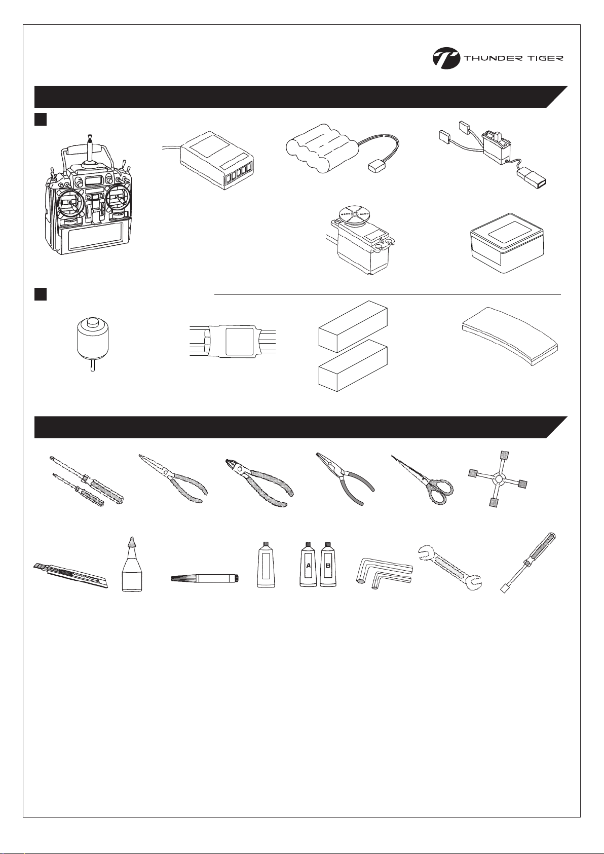
OTHER ITEMS REQUIRED /
RADIO SET / 遙控系統
其餘必須配件
Receiver
接收機
Transmitter (helicopter type
only, 6 or more channels)
發射機(需具備直昇機控制功能
的6動以上遙控器)
POWER SYSTEM / 動力系統
Electric Brushless Motor
無刷馬達
Electronic Speed Controller
速控器
TOOLS REQUIRED FOR ASSEMBLY /
Rx Battery
接收機電池
Servos
伺服機
12-14S Li-Po Battery Pack
鋰聚電池組
需要準備的工具
Switch Harness
具備充電線的開關組
3-AXIS Gyro
3軸陀螺儀
Foam
雙面膠帶
5.5mm
7mm
8mm
Screw Driver
各種規格的螺絲起子
Hobby Knife
美工刀
C.A Glue
瞬間膠
Needle Nose Pliers
尖嘴鉗
Threadlocker
螺絲防鬆膠
Nipper
斜口鉗
Grease
潤滑油
Ball Link Pliers
拆連桿頭的專用鉗子
Epoxy
環氧樹酯
Hex Wrench
六角板手
Scissors
剪刀
5.5mm
Metric 4-way Wrench
十字套筒板手
7mm
Wrench
開口板手
Socket Drivers
套筒螺絲起子
5.5mm
7mm
8mm
10mm
-4-
Page 6
A GUIDE TO THE INSTRUCTION MANUAL /
說明書操作指南
A: Indicates the assembly step number and the parts bags that
are to be assembled.
B: Displays actual size drawings, and part quantities used.
C: Refer to parts drawing or exploded view in the last few pages
of this manual, order the corresponding item no. for correct
replacement parts.
D: This instruction manual uses several symbols. Pay careful
attention to them during construction. Details are given at
the bottom of each page.
A: 顯示組立步驟及需組立之零件包順序。
B: 零件實際對照尺寸及使用數量。
C: 請比對零件形狀以及後附零件包圖示或爆炸圖找出需求零件料號。
D: 操作說明符號可更有效協助組裝者使用此說明書,請依說明書符號
指示進行組裝步驟。
C
Example 說明範例
A
B
C
B
D
SYMBOLS USED THROUGHOUT THE MANUAL /
The parts in the KIT are packed according to each major assembly steps. The part number and quantity are always
shown in the table on each page. As good practice, only open up the bag that you need for the paticular assembly.
零件均依照組裝步驟包裝,請依照組裝程序,逐一開啟零件包,避免零件遺失。
Note / 注意
Assembly drawings will contain icons that indicate use of
Threadlocker or CA glue as needed.
Examples of the icons are as right shown:
請依組裝步驟圖示,使用防鬆膠或接著劑。
圖示範例如右:
Apply C.A Glue
使用快乾膠黏合
Apply threadlocker
使用螺絲防鬆膠
Assemble as many times as specified
依指示組裝所需數量
Assemble left and right side the same way
左右側組件相同
Cut off shaded portion
依標示部分裁切
Ensure smooth, non-binding movement when assembling
確認組件靈活度
Drill holes with the specified diameter
依標示尺寸鑽孔
Must be purchased separately
改裝品需另購
符號說明
T22(#262) THREADLOCKER / 螺絲防鬆膠
CA CA GLUE / 快乾膠
Cut off excess
裁剪多餘部分
Apply grease
使用潤滑油膏(黃油)
Pay close attention here
注意組裝步驟
Hint
組裝提示
Assemble in right order
依標示順序組裝
-5-
Page 7
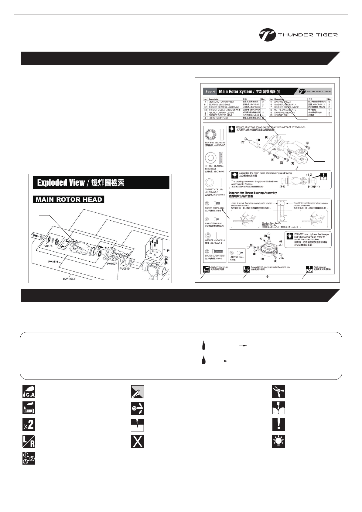
Bag A
Main Rotor System /
主旋翼機構組裝
Description
No.
1
METAL ROTOR GRIP SET
1-1
BEARING, d8xD16xW5
THRUST BEARING, d8xD16xW5
1-2
THRUST COLLAR, d8xD12xW0.5
1-3
FBL ROTOR GRIP LEVER
2
SOCKET SCREW, M3x6
3
ROTOR GRIP POST
4
BEARING, d8xD16xW5
滾珠軸承, d8xD16xW5
THRUST BEARING,
d8xD16xW5
止推軸承, d8xD16xW5
名稱
金屬主旋翼轉座組
滾珠軸承,d8xD16xW5
止推軸承, d8xD16xW5
止推軸環, d8xD12xW0.5
無平衡翼金屬旋翼轉座搖臂
內六角螺絲, M3x6
金屬主旋翼轉座支柱
Qty
2
2
1
1
2
4
2
No.
5
LINKAGE BALL(A)
6
WASHER, d3xD8xW1.4
SOCKET SCREW, M3x12
7
METAL SWASHPLATE
8
SWASHPLATE POST
9
LINKAGE BALL
10
Secure all screws shown on this page with a drop of threadlocker.
本頁顯示之螺絲請使用適量防鬆膠鎖固。
(2)
(4)
(5)
(6)
(7)
(3)
Assemble the main rotor pitch housing as drawing
主旋翼轉座組裝圖
(1)
名稱
內六角連接頭螺絲(A)
墊圈, d3xD8xW1.4
內六角螺絲, M3x12
十字盤組
十字盤球型支柱
大球頭
(3)
(1-2)
QtyDescription
6
2
2
1
2
1
THRUST COLLAR,
d8xD12xW0.5
止推軸環, d8xD12xW0.5
SOCKET SCREW, M3x6
內六角螺絲, M3x6
LINKAGE BALL(A)
內六角連接頭螺絲(A)
WASHER, d3xD8xW1.4
墊圈, d3xD8xW1.4
The bearings come with the grips which had been
assembled by Factory.
主旋翼夾座內軸承已由原廠壓配完成。
Diagram for Thrust Bearing Assembly
止推軸承安裝示意圖
Large Internal Diameter always goes toward
the Main Rotor Hub
內徑較大的一側,面向主旋翼固定座組(內側)。
Checking Tips: >
轉動角度: >
(轉動角度大者,內孔大;轉動角度小者,內孔小)
(9)
(5)
(9)
(1-1) (1-1)
Small Internal Diameter always goes
toward the Blade
內徑較小的一側,面向主旋翼組(外側)。
(1-3)
DO NOT over tighten the linkage
ball while securing in order to
(5)
avoid the screw broken.
鎖固時,切勿過度迫緊連接頭螺絲
以避免螺牙段斷裂。
SOCKET SCREW, M3x12
內六角螺絲, M3x12
Apply threadlocker
使用螺絲防鬆膠
LINKAGE BALL
大球頭
(5)
(8)
(10)
(5)
Assemble left and right side the same way
左右側組件相同
-6-
Apply grease
使用潤滑油膏(黃油)
Page 8
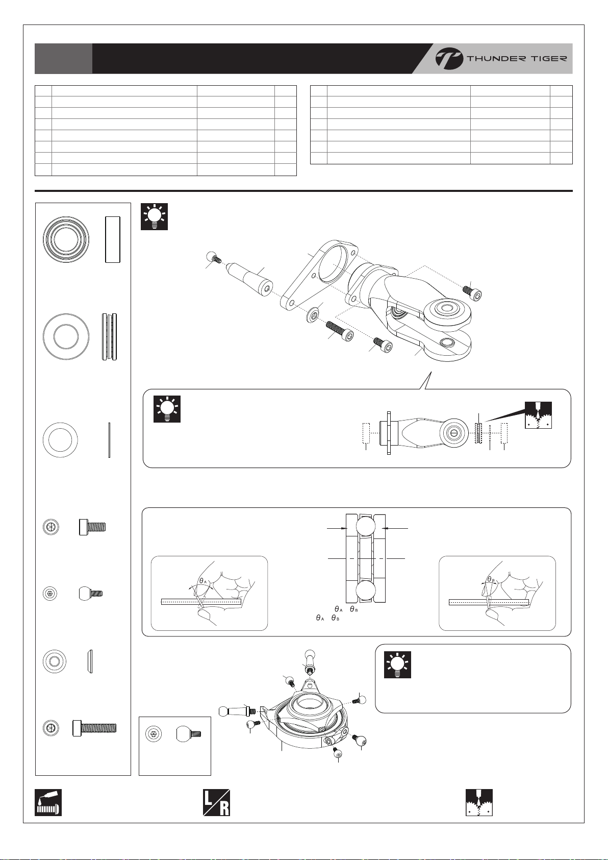
Bag A
Main Rotor System & Linkage Rod / 主旋翼機構及連桿組裝
No.
1
HARDENED MAIN SHAFT(15mm)
2
SOCKET SCREW, M4x6
3
METAL SWASHPLATE
4
SOCKET SCREW, M3x10
5
FBL WASHOUT BASE
6
FBL CONTROL LEVER
7
BEARING, d4xD8xW3
8
COLLAR, d3xD4xW8.5
9
SOCKET SCREW, M3x14
10
SET SCREW, M3x4
11
PIN,φ2x19
12
FBL WASHOUT LINKAGE
13
LINKAGE BALL(A)
14
THRUST COLLAR, d8xD12xW0.5
Secure all screws shown on this page
with a drop of threadlocker.
本頁顯示之螺絲請使用適量防鬆膠鎖固。
Scale=1:1 (unit:mm)
(26-2)
(26-1)
48.4
30
名稱
強化主軸(15mm)
內六角螺絲, M4x6
十字盤組
內六角螺絲, M3x10
無平衡翼控制臂座
無平衡翼控制搖臂
滾珠軸承, d4xD8xW3
軸套, d3xD4xW8.5
內六角螺絲, M3x14
無頭內六角螺絲, M3x4
軸承滾針,φ2x19
無平衡翼連接座
內六角連接頭螺絲(A)
止推軸環, d8xD12xW0.5
(25)
(24)
QtyDescription
No.
15
1
16
4
17
1
18
1
19
1
20
2
21
4
22
2
23
2
24
2
25
2
26
2
26-1
2
26-2
2
BEARING,
d4xD8xW3
滾珠軸承,d4xD8xW3
COLLAR,
d3xD4xW8.5
軸套, d3xD4xW8.5
THRUST COLLAR, d8xD12xW1.0
THRUST COLLAR, d8xD12xW0.2
THRUST COLLAR, d8xD12xW0.1
SPINDLE
OUTER DAMPER
INNER DAMPER
WASHER, d5xD11xW1.7
SOCKET SCREW, M5x10
FBL MAIN ROTOR HUB
FBL HEAD BUTTON
SOCKET SCREW, M2.5x10
LINKAGE ROD SET(48.4mm)
LINGAGE ROD(N)
BALL LINK
SOCKET SCREW, M3x14
內六角螺絲, M3x14
SET SCREW, M3x4
無頭內六角螺絲, M3x4
PIN, φ2x19
軸承滾針, φ2x19
(18)
名稱
止推軸環, d8xD12xW1.0
止推軸環, d8xD12xW0.2
止推軸環, d8xD12xW0.1
固定軸
外避震墊圈
內避震墊圈
華司, d5xD11xW1.7
內六角螺絲, M5x10
無平衡翼金屬主旋翼固定座
無平衡翼煞車盤
內六角螺絲, M2.5x10
連接桿組(48.4mm)
連接桿(鍍鎳)
單頭連接桿
LINKAGE BALL(A)
內六角連接頭螺絲(A)
WASHER, d5xD11xW1.7
華司, d5xD11xW1.7
SOCKET SCREW, M5x10
內六角螺絲, M5x10
QtyDescription
2
2
2
1
2
2
2
2
1
1
4
2
1
2
(26-2)
x2
SOCKET SCREW, M4x6
內六角螺絲, M4x6
SOCKET SCREW, M3x10
內六角螺絲, M3x10
Apply grease
使用潤滑油膏(黃油)
Ensure smooth, non-binding
movement when assembling
確認組件靈活度
Assemble left and right
side the same way
左右側組件相同
Apply threadlocker
使用螺絲防鬆膠
(26)
(2)
(4)
(3)
(1)
(23)
(13)
(5)
(8)
(26)
(6)
(19)
(2)
The holes should
point up.
有2孔的一端應朝上
(11)
(7)
(7)
(9)
(20)
(10)
(14~17)
(12)
SOCKET SCREW, M2.5x10
內六角螺絲, M2.5x10
(21)
(22)
d8xD12
please reallocate the different
thickness of Thrust Collars for
getting a proper mesh if too much
play or over tight.
完成組裝後,請轉動主旋翼轉座確認
作動是否順暢;如間隙過大或過緊,
請更改不同厚度之止推軸環組合以獲
得適當間隙。
(1.0mm) (0.5mm) (0.2mm) (0.1mm)
Rotate the Main Rotor
Grip to check if it runs
effortlessly and smoothly;
-7-
Page 9

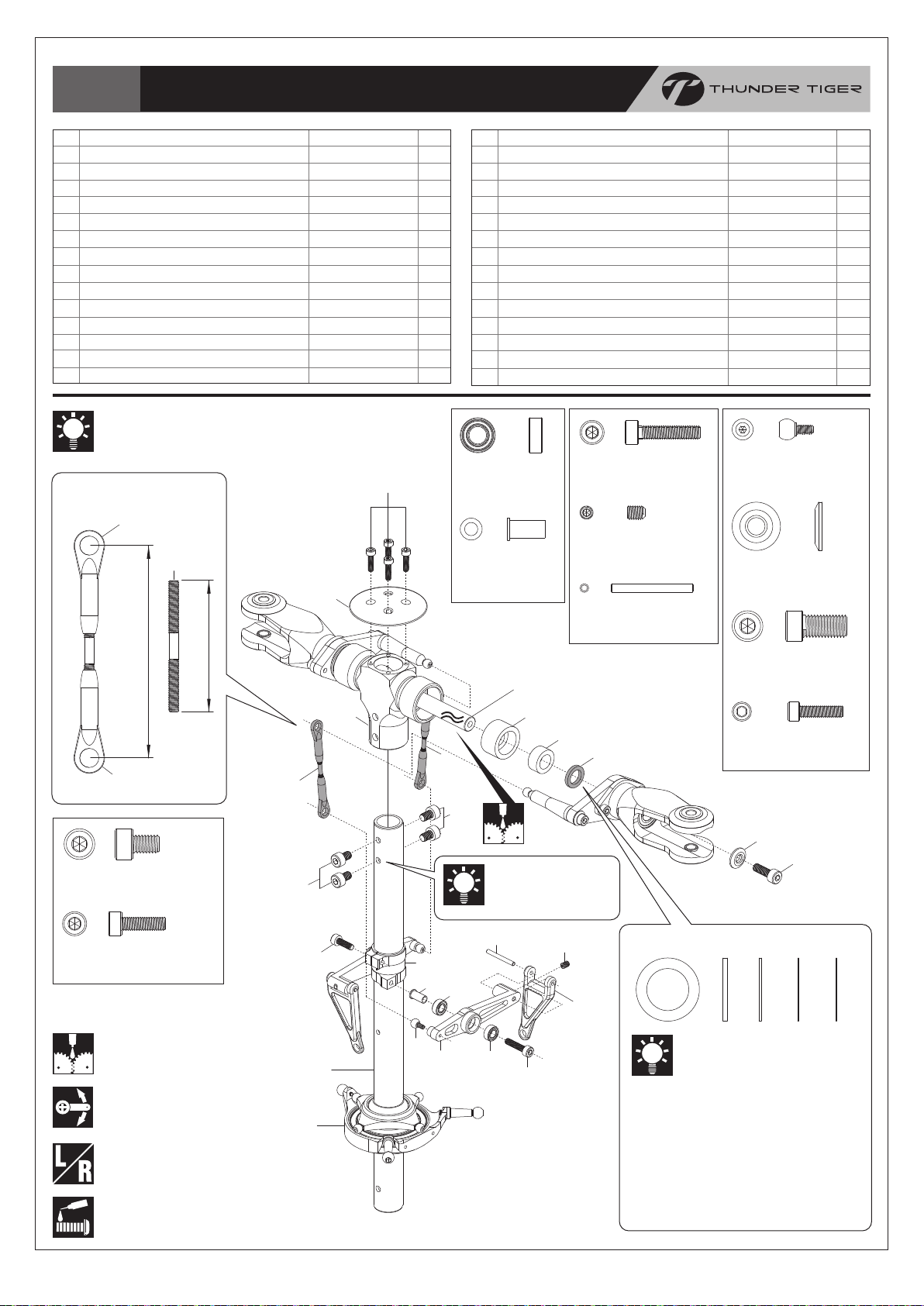
Bag B
Tail Boom Bracket Assembly /
尾管固定座組裝
No.
1
TAIL BOOM BRACKET-R
2
TAIL BOOM BRACKET-L
3
TAIL DRIVE BEVEL GEAR-B
4
BEARING, d12xD18xW4
5
BEVEL COLLAR,d12xD13.6xW11.85
6
TAIL DRIVE GEAR SHAFT
7
TAIL DRIVE GEAR-26T
8
TAIL DRIVE BEVEL GEAR-A
BEARING, d12xD18xW4
滾珠軸承, d12xD18xW4
BEVEL COLLAR,
d12xD13.6xW11.85
傘齒軸環, d12xD13.6xW11.85
T22
名稱
機身尾管固定座(右)
機身尾管固定座(左)
尾驅動傘齒B(24T)
滾珠軸承, d12xD18xW4
傘齒軸環,
尾驅動齒輪軸
尾驅動齒輪26T
尾驅動傘齒A(27T)
(4)
(5)
(4)
QtyDescription
1
1
1
2
d12xD13.6xW11.85
1
1
1
1
(3)
(11)
(10)
No.
9
PIN, φ2x12
10
BEARING, d5xD13xW4
11
SET SCREW, M3x4
12
SELF-TAPPING SCREW, M2.6x16
13
FRAME SPACER
14
SOCKET SCREW, M3x25
15
LOCK NUT, M3
16
SOCKET SCREW, M3x14
名稱
固定銷, φ2x12
滾珠軸承
, d5xD13xW4
無頭內六角螺絲, M3x4
扁圓自攻螺絲(粗)
側板支柱
內六角螺絲, M3x25
止鬆螺帽, M3
內六角螺絲, M3x14
QtyDescription
2
2
2
2
4
4
5
1
PIN, φ2x12
固定銷, φ2x12
BEARING, d5xD13xW4
滾珠軸承, d5xD13xW4
SET SCREW, M3x4
無頭內六角螺絲, M3x4
SELF-TAPPING SCREW, M2.6x16
扁圓自攻螺絲(粗)
SOCKET SCREW, M3x25
內六角螺絲, M3x25
T22
(10)
(11)
(8)
(6)
(7)
(9)
(9)
(1)
(14)
(16)
(2)
(12)
LOCK NUT, M3
止鬆螺帽, M3
SOCKET SCREW, M3x14
內六角螺絲, M3x14
(15)
(15)
Apply threadlocker
使用螺絲防鬆膠
(13)
Assemble the Tail Boom Bracket as
drawing. Secure the Screws but do
not tighten at this step.
參考圖示組裝尾管固定座,螺絲只需稍
事固定,暫無需鎖緊。
-8-
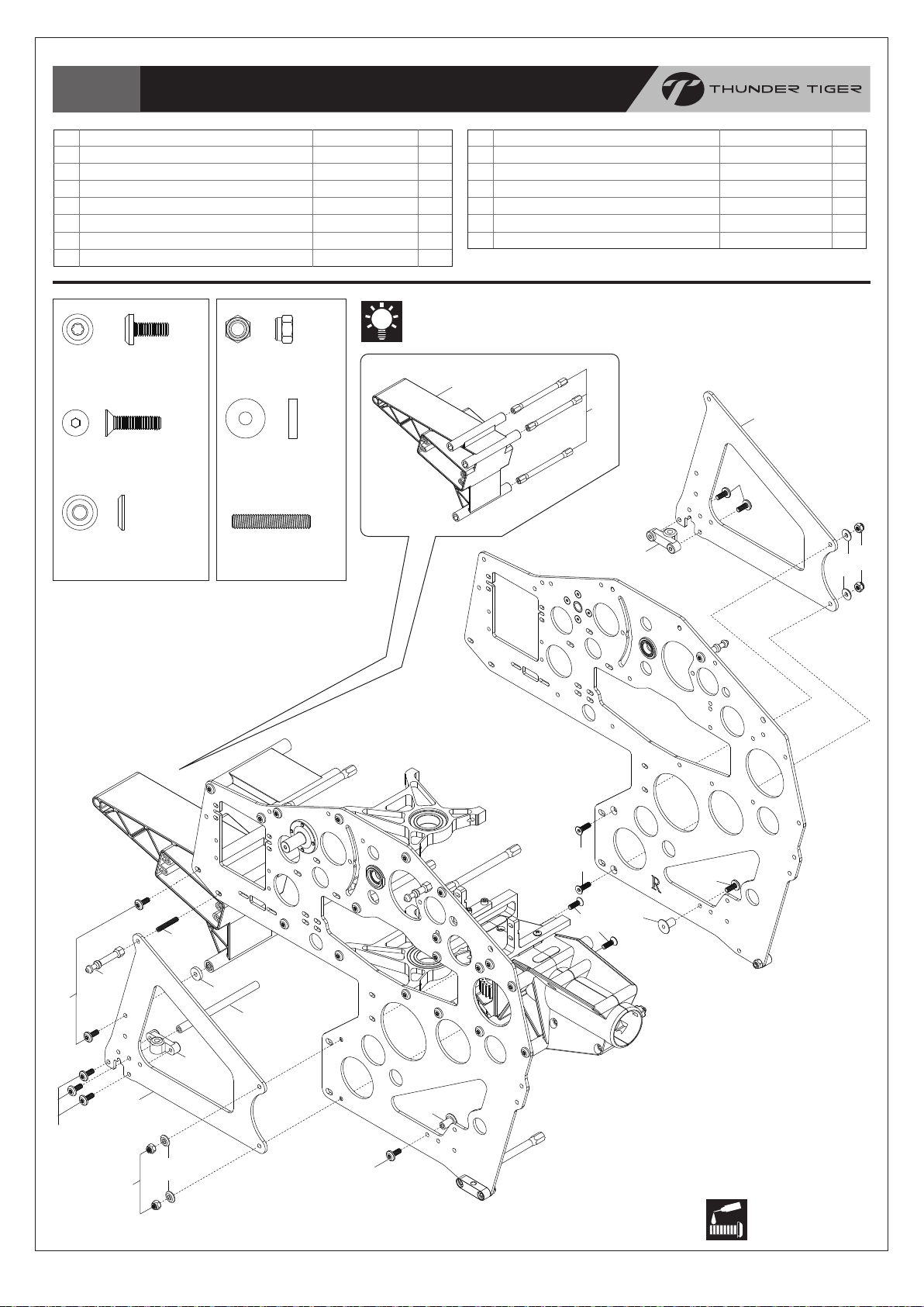
Page 10
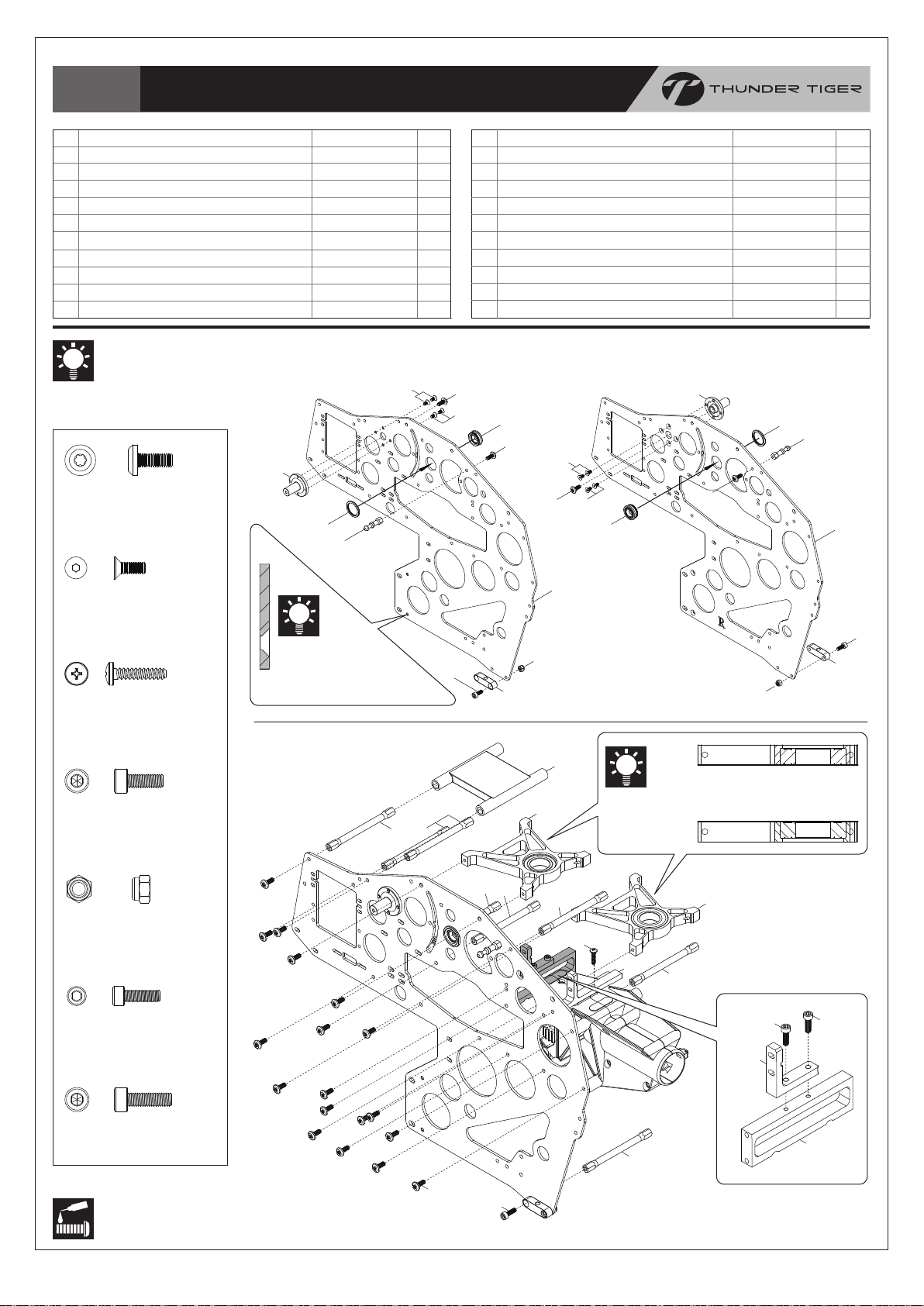
Bag C+D
Main Frame /
本體組裝
No.
1
SIDE FRAME-L
2
SIDE FRAME-R
3
CANOPY RETAINING POST
4
TORX SCREW, M3x8
5
ELEVATOR WASHER MOUNT SET
6
NUT
7
CONTROL ARM BASE
8
SINK SOCKET SCREW, M2.5x5
9
BUTTON PHILLIPS TAPPING SCREW, M2.6x12
10
SKID BRACKET
Secure all screws & Washer Mount shown
on this page with a drop of threadlocker.
本頁顯示之螺絲及控制臂軸承座請使用適量防
鬆膠鎖固。
(7)
TORX SCREW, M3x8
星型螺絲
名稱
碳纖側板-左
碳纖側板-右
機身固定柱
星型螺絲, M3x8
控制臂軸承座
軸承座螺帽
控制臂固定座
沈頭內六角螺絲, M2.5x5
扁圓自攻螺絲(粗), M2.6x12
腳架固定座
(6)
(3)
(8)
QtyDescription
22
No.
1
1
2
2
2
2
8
1
2
11
12
13
14
15
16
17
18
19
20
Left Frame
(4)
(8)
SOCKET SCREW, M3x8
LOCK NUT, M3
FRAME SPACER
SERVO TRAY
SERVO MOUNT
SERVO MOUNT
SOCKET SCREW(N), M2.5x8
GYRO TRAY
SOCKET SCREW, M3x10
MAIN SHAFT BRG BLOCK SET
左側板
(5)
(4)
(8)
(4)
(8)
(5)
(7)
名稱
內六角螺絲, M3x8
止鬆螺帽, M3
側板支柱
伺服機座
伺服機固定座
伺服機固定座
內六角螺絲(鎳色), M2.5x8
陀螺儀座
內六角螺絲, M3x10
主軸軸承座
(4)
QtyDescription
2
2
8
1
1
1
2
1
1
2
Right Frame
右側板
(6)
(3)
(2)
SINK SOCKET SCREW, M2.5x5
沈頭六角螺絲, M2.5x5
The larger hole
always goes toward
the inner side.
BUTTON PHILLIPSTAPPING SCREW, M2.6x12
扁圓自攻螺絲(粗), M2.6x12
SOCKET SCREW, M3x8
內六角螺絲, M3x8
LOCK NUT, M3
止鬆螺帽, M3
SOCKET SRCEW, M2.5x8
內六角螺絲, M2.5x8
請注意螺絲鎖固孔徑較大者朝內。
(13)
(11)
(13)
(10)
(12)
(20)
(13)
(1)
(18)
(9)
(12)
Upper
The flat surface of the Block always
goes toward the inner side (Main Gear).
軸承座上平面一側朝內(朝向主齒盤)。
Lower
(20)
(16)
(13)
(17)
(15)
(11)
(10)
(17)
SOCKET SRCEW, M3x10
內六角螺絲, M3x10
Apply threadlocker
使用螺絲防鬆膠
(4)
-9-
(19)
(13)
(14)
Page 11
Bag D
Main Frame /
本體組裝
No.
1
RADIO TRAY
2
TORX SCREW, M3x8
3
FRAME SPACER
4
SINK SOCKET SCREW, M3x10
5
WASHER, d3xD8xW1.4
6
LOCK NUT, M3
7
BATTERY PIN
TORX SCREW, M3x8
星型螺絲, M3x8
SINK SOCKET SCREW, M3x10
沈頭內六角螺絲, M3x10
WASHER, d3xD8xW1.4
墊圈, d3xD8xW1.4
名稱
油門伺服機固定架
星型螺絲, M3x8
側板支柱
沈頭內六角螺絲, M3x10
墊圈, d3xD8xW1.4
止鬆螺帽, M3
電池盒軸襯
LOCK NUT, M3
止鬆螺帽, M3
SPACER, d3xD9xW2
墊圈, d3xD9xW2
SET SCREW, M3x18
無頭內六角螺絲
, M3x18
QtyDescription
No.
8
1
9
3
4
4
4
2
SPACER, d3xD9xW2
9
LOWER SIDE FRAME
10
BATTERY POST
11
REAR SKID BRACKET
12
SET SCREW, M3x18
13
CANOPY RETAINING POST(L)
名稱
墊圈, d3xD9xW2
碳纖下側板
電池盒支柱
支撐架固定座
無頭內六角螺絲
機身固定柱(長)
Secure all screwsshown on this page with a drop of threadlocker.
本頁顯示之螺絲請使用適量防鬆膠鎖固。
(1)
(3)
(9)
(2)
(11)
(5)
QtyDescription
1
2
1
2
1
1
(6)
(2)
(2)
(13)
(6)
(9)
(5)
(12)
(11)
(8)
(10)
(2)
(7)
-10-
(4)
(4)
(2)
(7)
Apply threadlocker
使用螺絲防鬆膠
Page 12

Bag D
Main Frame /
本體組裝
No.
1
TORX SRCEW, M3x8
2
SOCKET SRCEW, M3x10
3
SET SCREW, M3x18
4
CANOPY RETAINING POST(L)
5
SPACER, d3xD9xW2
6
METAL ELEVATOR CONTROL ARM
7
LINKAGE BALL(A)
TORX SRCEW, M3x8
星型螺絲, M3x8
SOCKET SRCEW, M3x10
內六角螺絲, M3x10
SET SCREW, M3x18
無頭內六角螺絲
, M3x18
SPACER, d3xD9xW2
墊圈, d3xD9xW2
LINKAGE BALL(A)
內六角連接頭螺絲(A)
BEARING, d2.5xD7xW3.5
滾珠軸承, d2.5xD7xW3.5
名稱
星型螺絲, M3x8
內六角螺絲, M3x10
無頭內六角螺絲
機身固定柱(長)
墊圈, d3xD9xW2
升降舵控制臂組
內六角連接頭螺絲(A)
SOCKET SRCEW, M2.5x8
內六角螺絲, M2.5x8
SET SCREW, M4x4
無頭內六角螺絲, M4x4
QtyDescription
29
No.
8
ELEVATOR CONTROL ARM LINK
1
1
1
1
1
2
9
BEARING, d2.5xD7xW3.5
10
SOCKET SRCEW, M2.5x8
11
U TYPE MOTOR MOUNT
12
SET SCREW, M4x4
13
MOTOR PINION(8mm),11T
14
MOTOR PINION(8mm),12T
名稱
升降舵連接座
滾珠軸承, d2.5xD7xW3.5
內六角螺絲, M2.5x8
U型馬達座組
無頭內六角螺絲, M4x4
馬達齒輪(8mm,11T)
馬達齒輪(8mm,12T)
QtyDescription
1
2
2
1
2
1
1
Secure all screws shown on this page with a drop
of threadlocker.
本頁顯示之螺絲請使用適量防鬆膠鎖固。
Applicable to a M4x30mm or M4x25mm
motors with 4 setting screws installation.
A 8.0mm/0.315” diameter motor shaft as
standard and 38mm/1.496” long shaft is
recommended.
可適用M4x30mm或M4x25mm 鎖固孔位馬達。
原廠馬達齒及馬達齒輪固定座可裝配8.0mm/0.315”
軸心馬達,建議馬達軸心長度為38mm/1.496”。
(13~14)
(11)
(12)
(1)
(10)
(9)
(6)
(8)
(9)
(10)
(2)
(7)
(4)
(7)
(3)
(1)
(1)
(5)
Apply threadlocker
使用螺絲防鬆膠
Ensure smooth, non-binding movement
when assembling 確認組件靈活度
Must be purchased
separately
改裝品需另購
(1)
-11-
Page 13
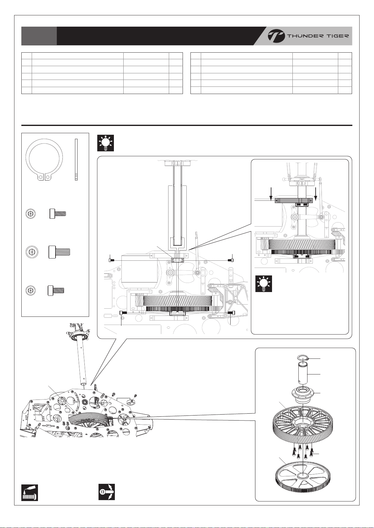
Bag E
Main Gear Set /
主齒輪組組裝
No.
1
MAIN GEAR SET
1-1
MAIN GEAR,111T
1-2
TAIL DRIVE GEAR,108T
1-3
ONE WAY BEARING SHAFT
1-4
C-CLIP
C-CLIP
C型扣環
SOCKET SCREW, M2.5x6
內六角螺絲
, M2.5x6
名稱
主齒輪組
主齒輪(111T)
尾驅動輪108T
單向離合器軸
C型扣環
QtyDescription
No.
1-5
1
1
1
1
1
SOCKET SCREW, M2.5x6
1-6
ONE WAY CLUTCH HOUSING
2
SOCKET SCREW, M4x8
3
MAIN SHAFT STOPPER
4
SOCKET SCREW, M3x6
Secure all screws shown on this page with a drop of threadlocker.
本頁顯示之螺絲請使用適量防鬆膠鎖固。
名稱
內六角螺絲, M2.5x6
單向離合器座
內六角螺絲, M4x8
止擋環
內六角螺絲, M3x6
QtyDescription
8
1
2
1
2
SOCKET SCREW, M4x8
內六角螺絲, M4x8
SOCKET SCREW, M3x6
內六角螺絲, M3x6
(1)
(4)
(2)
(3)
(4)
(2)
Lower the Upper Main Shaft
Bearing Block to eliminate the
play after securing all screws.
鎖固定位螺絲後,將上主軸軸承座下
壓以消除間隙。
(1-4)
(1-3)
(1-1)
(1-6)
Line up the holes of the Autorotation Tail Drive Gear, One Way Bearing Shaft &
Main Shaft, and then insert the Socket Screw to fix. Add a drop of threadlocker
when securing, but do not over tighten.
對正尾驅動齒、單向軸套及主軸上孔位後,鎖入內六角螺絲,並使用適量防鬆劑固定。
注意! 請勿過度緊迫螺絲。
Apply threadlocker
使用螺絲防鬆膠
Ensure smooth, non-binding movement
when assembling 確認組件靈活度
-12-
(1-2)
(1-5)
Page 14
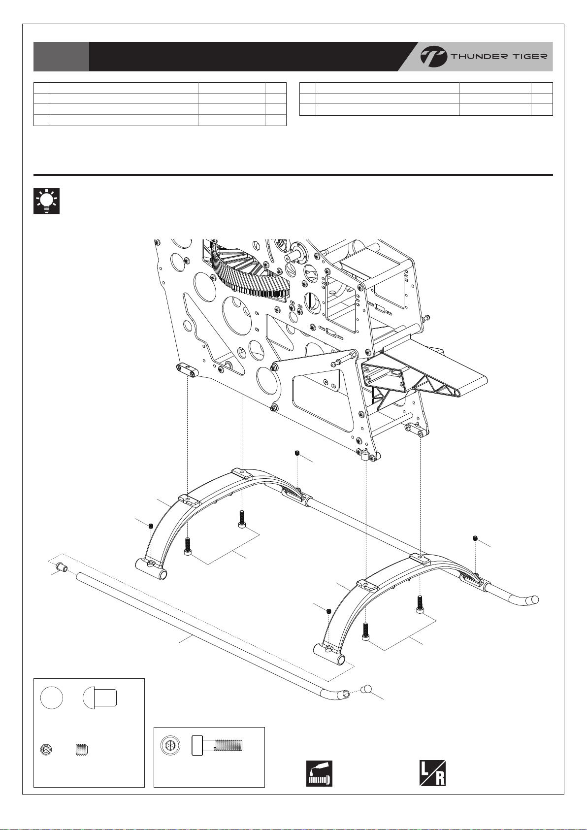
Bag F
Landing Skid /
腳架組組裝
No.
1
LANDING SKID BRACE
2
SKID PIPE
3
SKID PIPE END CAP
Secure all screws shown on this page with a drop of threadlocker.
本頁顯示之螺絲請使用適量防鬆膠鎖固。
名稱
腳架
底座圓管
圓管塞
QtyDescription
2
2
4
No.
4
SET SCREW, M4x4
5
SOCKET SCREW, M4x14
名稱
無頭內六角螺絲, M4x4
內六角螺絲, M4x14
QtyDescription
4
4
(3)
SKID PIPE END CAP
圓管塞
(4)
(1)
(2)
(4)
(4)
(5)
(1)
(4)
(5)
(3)
SET SCREW, M4x4
無頭內六角螺絲, M4x4
SOCKET SCREW, M4x14
內六角螺絲, M4x14
-13-
Apply threadlocker
使用螺絲防鬆膠
Assemble left and right
side the same way
左右側組件相同
Page 15

Bag F
Control Arm Set /
控制臂組組裝
No.
CONTROL ARM SET-L
1
CONTROL ARM-L
1-1
LINK BALL
1-2
SOCKET SCREW, M2x8
1-3
LINKAGE BALL(A)
1-4
BEARING, d8xD12xW3.5
1-5
名稱
側轉控制臂座組-左
側轉控制臂座-左
連結球座
內六角螺絲, M2x8
內六角連接頭螺絲(A)
滾珠軸承, d8xD12xW3.5
QtyDescription
No.
2
1
1
2
2
4
4
SOCKET SCREW, M2.5x6
3
CONTROL ARM SET-R
3-1
CONTROL ARM-R
4
LINKAGE ROD SET(67.5mm)
5
CONTROL ARM CAP
名稱
內六角螺絲, M2.5x6
金屬副翼控制臂組-右
金屬副翼控制臂A-右
連接桿(67.5mm)
墊圈
Secure all screws shown on this page with a drop of threadlocker.
本頁顯示之螺絲請使用適量防鬆膠鎖固。
Attach the Control Arm onto the Main Frames as drawing, and note the difference of Left & Right Control Arms.
參考圖示將控制臂裝上側板上,請注意左、右邊方向性。
Scale=1:1 (unit:mm)
67.5 (Fixed Length)
LINK BALL
連結球座
The length of the Linkage
Rod Set is fixed (67.5mm)
without adjustment req’d.
此處連桿長度固定為67.5mm,
長度無需進行調整。
SOCKET SCREW, M2x8
內六角螺絲, M2x8
(4)
LINKAGE BALL(A)
內六角連接頭螺絲(A)
(1)
QtyDescription
2
1
1
2
2
x2
(2)
(5)
BEARING, d8xD12xW3.5
滾珠軸承, d8xD12xW3.5
SOCKET SCREW, M2.5x6
內六角螺絲, M2.5x6
(3-1)
(1-3)
(1-4)
(1-5)
(1-4)
(1-2)
(2)
(4)
(5)
(1-5)
(3)
(1-3)
(1-1)
(1-4)
(1-5)
(1-2)
(1-5)
Apply threadlocker
使用螺絲防鬆膠
Ensure smooth, non-binding movement
when assembling 確認組件靈活度
-14-
Page 16

Bag G
Tail Rotor System /
尾旋翼機構組裝
No.
1
METAL TAIL GRIP
2
WASHER, d7.5xD10xW0.3
3
WASHER, d7.5xD5xW0.3
4
THRUST BEARING, d5xD10xW4
5
BEARING, d5xD10xW4
6
TAIL ROTOR HUB
7
SET SCREW, M3x3
8
WASHER, d3xD7xW0.5
9
TORX SCREW, M3x8
10
TAIL PITCH CONTROL LINK
名稱
金屬尾旋翼轉座
止推軸環, d7.5xD10xW0.3
止推軸環, d7.5xD5xW0.3
止推軸承, d5xD10xW4
滾珠軸承, d5xD10xW4
尾旋翼座
無頭內六角螺絲, M3x3
墊圈, d3xD7xW0.5
星型螺絲, M3x8
尾旋翼連接頭
QtyDescription
2
2
2
2
2
1
2
2
2
2
Secure all screws shown on this page with a drop of threadlocker.
本頁顯示之螺絲請使用適量防鬆膠鎖固。
COLLAR,
WASHER,
d7.5xD10xW0.3
止推軸環, d7.5xD10xW0.3
WASHER
d7.5xD5xW0.3
止推軸環 d7.5xD5xW0.3
THRUST BEARING,
d5xD10xW4
止推軸承, d5xD10xW4
WASHER,
d3xD7xW0.5
墊圈, d3xD7xW0.5
TORX SCREW, M3x8
星型螺絲, M3x8
SOCKET SCREW, M2x8
內六角螺絲, M2x8
d2xD3xW4.2
軸環,d2xD3xW4.2
PIN, φ2x19
固定銷, φ2x19
1. Note the orientation of the Thrust Bearings; please refer
2. Line up the concave of Tail Rotor Shaft and the hole of Hub
1. 請參考第 6 頁止推軸承安裝示意圖,注意安裝方向性。
2. 將尾旋翼固定座鎖上尾旋翼主軸時,請注意軸上凹槽需對正固定座
No.
SOCKET SCREW, M2x8
11
COLLAR, d2xD3xW4.2
12
PIN, φ2x19
13
E-CLIP
14
TAIL ROTOR SHAFT
15
TAIL PITCH CONTROL FORK
16
METAL TAIL PITCH SLIDER
17
BEARING, d6xD10xW3
18
TAIL PITCH CONTROL SLIDER BUSHING
19
LINKAGE BALL(A)
20
E-CLIP
E型扣環
BEARING, d6xD10xW3
滾珠軸承, d6xD10xW3
名稱
內六角螺絲, M2x8
軸環, d2xD3xW4.2
固定銷, φ2x19
E型扣環
尾旋翼軸
尾旋翼控制座
金屬尾旋翼滑座
滾珠軸承
, d6xD10xW3
尾旋翼控制軸套
內六角連接頭螺絲(A)
LINKAGE BALL(A)
內六角連接頭螺絲(A)
page 6, Diagram for Thrust Bearing Assembly.
when securing the Tail Rotor Hub onto the Tail Rotor Shaft.
上螺絲孔。
QtyDescription
2
2
2
2
1
1
1
2
1
1
BEARING, d5xD10xW4
滾珠軸承, d5xD10xW4
SET SCREW, M3x3
無頭內六角螺絲, M3x3
(18)
(19)
Apply threadlocker
使用螺絲防鬆膠
(15)
(18)
(17)
(20)
Assemble left and right
side the same way
左右側組件相同
(13)
(16)
(7)
(6)
(11)
(12)
(14)
(7)
(10)
The bearing had been
assembled by Factory
此軸承已由原廠組裝完成
Completed View
組裝完成
Ensure smooth, non-binding movement
when assembling 確認組件靈活度
(1)
(5)
(2)
(4)
(3)
(5)
(8)
(9)
Apply grease
使用潤滑油膏(黃油)
-15-
Page 17

(18)
(18)
(14)
(13)
(17)
(13)
(16)
(19)
(19)
(12)
(8)
(9)
(15)
(7)
Bag H
Tail Rotor System /
尾旋翼機構組裝
No.
1
METAL TAIL UNIT HOUSING
2
BEARING, d12xD18xW4
3
COLLAR, d16.5xD18xW6.83
4
COLLAR, d12xD13xW6.85
5
TAIL INPUT BEVEL
6
FLANGE BEARING, d5xD13xW4
7
TAIL OUTPUT BEVEL
8
PIN, φ2x12
9
SET SCREW, M3x4
10
TAIL LEVER BKT
BEARING, d12xD18xW4
滾珠軸承, d12xD18xW4
COLLAR,
d16.5xD18xW6.83
尾座軸承間隔環,
d16.5xD18xW6.83
名稱
金屬尾座
滾珠軸承, d12xD18xW4
尾座軸承間隔環
尾傘齒軸環
尾螺旋傘齒輪A(24T)
凸緣軸承,d5xD13xW4
尾螺旋傘齒輪B(24T)
軸承滾針, φ2x12
無頭內六角螺絲, M3x4
金屬尾控制臂座
BEARING, d4xD7xW2.5
滾珠軸承, d4xD7xW2.5
WASHER, d3xD5xW0.5
墊片, d3xD5xW0.5
COLLAR, d3xD4xW10
軸環, d3xD4xW10
SOCKET SCREW, M3x16
內六角螺絲, M3x16
QtyDescription
No.
11
1
2
1
1
1
2
1
1
1
1
SOCKET SCREW, M2.5x8
12
TAIL PITCH CONTROL LEVER
13
BEARING, d4xD7xW2.5
14
WASHER, d3xD5xW0.5
15
COLLAR, d3xD4xW10
16
SOCKET SCREW, M3x16
17
LINKAGE BALL(B)
18
LOCK NUT, M3
19
SOCKET SCREW, M3x18
名稱
內六角螺絲, M2.5x8
尾旋翼控制桿
滾珠軸承, d4xD7xW2.5
墊片, d3xD5xW0.5
軸環, d3xD4xW10
內六角螺絲, M3x16
內六角連接頭自攻螺絲(B)
止鬆螺帽, M3
內六角螺絲, M3x18
QtyDescription
Secure all screws shown on this page with a drop of threadlocker.
本頁顯示之螺絲請使用適量防鬆膠鎖固。
(1)
(1)
(6)
(11)
(10)
(6)
(2)
(4)
(3)
(2)
(5)
2
1
2
1
1
1
1
2
2
COLLAR,
d12xD13xW6.85
尾傘齒軸環,
d12xD13xW6.85
FLANGE BEARING,
d5xD13xW4
凸緣軸承, d5xD13xW4
PIN, φ2x12
軸承滾針, φ2x12
SET SCREW, M3x4
無頭內六角螺絲
SOCKET SCREW, M2.5x8
內六角螺絲, M2.5x8
Apply threadlocker
使用螺絲防鬆膠
, M3x4
LINKAGE BALL(B)
內六角連接頭自攻螺絲(B)
LOCK NUT, M3
止鬆螺帽, M3
SOCKET SCREW, M3x18
內六角螺絲, M3x18
Apply some of silicon oil or grease onto the gears.
(Using PV0269 Grease for Plastic Parts is recommended.)
在傘齒輪上塗抹些許矽膠油或塑膠零件潤滑油。
(推薦使用PV0269塑膠零件潤滑油)
Ensure smooth, non-binding movement
when assembling 確認組件靈活度
-16-
Must be purchased
separately
改裝品需另購
Apply grease
使用潤滑油膏(黃油)
Page 18

Bag I+J
(21)
(18)
(17)
(17)
(18)
(18)
(20)
(19)
(19)
(20)
(15)
(13)
(16)
(12)
(16)
(16)
(11)
(14)
(22)
Tail Unit /
尾部總成組裝
No.
1
TAIL DRIVE SHAFT
2
TAIL DRIVE SHAFT BRG
3
LOCK NUT, M2.5
4
TAIL DRIVE SHAFT LINKER
5
SOCKET SCREW, M2.5x12
6
CARBOM TAIL BOOM
7
TORX SCREW, M3x8
8
TAIL STOPPER
9
SOCKET SCREW, M3x10
10
CARBON VERTICAL FIN
11
METAL TAIL BOOM SUPPORT BRACKET
LOCK NUT, M2.5
止鬆螺帽, M2.5
SOCKET SCREW, M2.5x12
內六角螺絲, M2.5x12
TORX SCREW, M3x8
星型螺絲
名稱
尾驅動軸
尾驅動軸軸套組
止鬆螺帽, M2.5
尾驅動連接棒
內六角螺絲, M2.5x12
碳纖尾管
星型螺絲
尾管止擋塊
內六角螺絲, M3x10
碳纖垂直安定面
金屬尾管支撐固定座
SOCKET SCREW, M2x10
內六角螺絲, M2x10
, M3x8
(4)
(5)
(6)
QtyDescription
No.
12
1
2
2
2
2
1
2
1
1
1
1
SOCKET SCREW, M3x8
13
SOCKET SCREW, M3x6
14
METAL TAIL SERVO MOUNT
15
SELF TAPPING SCREW, M2x8
16
ROD GUIDE
17
TAIL BOOM SUPPORT END
18
SOCKET SCREW, M3x12
19
NUT, M2
20
SOCKET SCREW, M2x10
21
CARBON TAIL BOOM SUPPORT
22
FRAME SPACER
名稱
內六角螺絲, M3x8
內六角螺絲, M3x6
金屬伺服機固定座
自攻螺絲(粗), M2x8
推拉桿固定環
尾管支撐架接頭
內六角螺絲, M3x12
六角螺帽, M2
內六角螺絲, M2x10
碳纖尾管支撐架
側板支柱
Add a drop of thin CA glue on the Tail Drive Shaft next to where
the bearing should be, and then slide the bearings over the
position quickly; the distance from the Shaft Drive End to the
Rubber Shaft Bearing Support is approx. 278mm / 10.94”.
在尾傳動軸上軸承固定位置前方,塗抹少量快乾膠,迅速滑動軸承至定
位固定;該定位大約距離軸傳動接頭278mm / 10.94”處。
278mm/10.94”
(3)
C.A
(2)
(1)
278mm/10.94”
QtyDescription
1
2
2
3
3
4
4
4
4
2
1
SOCKET SCREW, M3x10
內六角螺絲, M3x10
SOCKET SCREW, M3x8
內六角螺絲, M3x8
SOCKET SCREW, M3x6
內六角螺絲, M3x6
SELF TAPPING SCREW, M2x8
自攻螺絲(粗), M2x8
SOCKET SCREW, M3x12
內六角螺絲, M3x12
NUT, M2
六角螺帽, M2
Rear View 後視圖
(22)
Secure the screws into the Frame
Spacer when attaching the Tail Boom
Support End on the Main Frames.
安裝尾管支撐架於側板上時,請注意需將
鎖固螺絲鎖固於六角固定支柱上。
(18)(18)
(2)
(9)
(3)
(4)
(5)
(7)
(8)
(10)
Apply threadlocker
使用螺絲防鬆膠
Assemble left and right
side the same way
左右側組件相同
-17-
Apply C.A Glue
使用快乾膠黏合
Page 19

Bag K
Servo Installation /
伺服機裝配
No.
SERVO HORN COLLAR
1
SERVO HORN
2
RUDDER SERVO HORN
3
LINK BALL
4
SERVO MOUNTING
5
Do not tighten the screw #9
& #10 at this step for
preforming servo of
calibations later.
螺絲#9
暫勿鎖緊以便後續
中立點調整。
(7)
(5)
(7)
(8)
(4)
(5)
(6)
(6)
名稱
伺服機擺臂軸套
伺服機擺臂
尾舵伺服機擺臂
連接球座
伺服機墊片
QtyDescription
No.
4
3
1
7
8
SERVO NUT
6
BUTTON PHILLIPS TAPPING SCREW, M2.6x14
7
BUTTON HEAD SOCKET SCREW, M3x5
8
SOCKET SCREW, M2.5x6
9
SET SCREW, M3x3
10
Screws should be separately
fastened diagonally to ensure
the servos mounted evenly.
鎖固時須依對角依序平均鎖上,
以使伺服機平整安裝於側板上。
Main Frame
側板
名稱
伺服機螺帽
扁圓自攻螺絲(粗), M2.6x14
半圓頭內六角螺絲, M3x5
內六角螺絲, M2.5x6
無頭內六角螺絲, M3x3
QtyDescription
8
16
4
4
4
(2)
(9)
(1)
LINK BALL
連接球座
BUTTON PHILLIPS TAPPING SCREW, M2.6x14
扁圓自攻螺絲(粗), M2.6x14
BUTTON HEAD SOCKET SCREW, M3x5
半圓頭內六角螺絲, M3x5
(10)
(7)
(1)
(5)
(4)
Attach the Servos onto the Servo Trays
of Main Frame Set as drawing.
參考圖示將伺服機裝入主側板組上伺服機座。
(6)
(6)
(8)
(5)
(3)
(10)
(9)
SOCKET SCREW, M2.5x6
內六角螺絲, M2.5x6
SET SCREW, M3x3
無頭內六角螺絲, M3x3
Apply threadlocker
使用螺絲防鬆膠
The adaptors come with the kit are applicable to ACR RC / Futaba servos as standard parts.
The option adaptors for JR or Hitec are also available separately:
套件內附標準之伺服機擺臂軸套適用於ACE RC及Futaba品牌伺服機。
JR或Hitec伺服機使用之軸套可另外購買:
Item No. PV1623-J Servo Horn Adaptor for JR 伺服機擺臂軸套, JR
Item No. PV1623-H Servo Horn Adaptor for Hitec 伺服機擺臂軸套, Hitec
Assemble left and right side the same way
左右側組件相同
Must be purchased separately
改裝品需另購
-18-
Page 20

Bag
J+KP1
Linkage Rod & Main Rotor Blade /
連桿及主旋翼組裝
No.
1
LINKAGE ROD
2
BALL LINK
3
LINKAGE ROD
SOCKET SCREW, M5x35
內六角螺絲, M5x35
LOCK NUT, M5
止鬆螺帽, M5
名稱
尾推拉桿
單頭連接桿
連接桿
QtyDescription
No.
4
1
2
6
ROTOR SPACER
5
SOCKET SCREW, M5x35
6
LOCK NUT, M5
名稱
主旋翼墊片
內六角螺絲, M5x35
止鬆螺帽, M5
QtyDescription
2
2
2
(3)
(4)
(5)
(2)
(1)
The length of the Linkage Rod Set is fixed
(74.53mm) without adjustment req’d.
此處連桿長度固定為74.53mm,長度無需進行調整。
Scale=1:1 (unit:mm)
74.53 (Fixed Length)
x6
(2)
(3)
(6)
(5)
(4)
(6)
(3)
1. You may need to adjust the linkage to ensure the blade tracking. Please refer page 27:Blade Tracking Adjustment.
2. Install the main blades with the Socket Screw. Do not over tighten and ensure the blades run effortlessly.
3. For safety the rpm of using carbon blades should not exceed 1,900rpm.
1. 您可能必需調整相關的連桿來確保旋翼旋轉軌跡正常。 請參閱第27頁〝主旋翼軌跡調整〞說明。
2. 以內六角螺絲安裝上主旋翼。請勿過度鎖緊。
3. 安全起見,碳纖維主旋翼轉速請勿超過1,900rpm。
Must be purchased separately
改裝品需另購
-19-
Page 21

Bag L
7S Li-Po Battery x 2 / 7S鋰電池 x 2
(1)
(5)
(5)
(4)
(4)
(3)
(3)
(2)
Electronic Speed Controller / 速控器
Electronic Device & Battery Tray / 電子設備及電池座組裝
No.
1
BATTERY TRAY
2
BATTERY TRAY CATCH
3
COLLAR, d3xD4xW3.1
COLLAR,
d3xD4xW3.1
軸套, d3xD4xW3.1
FLAT SCREW, M3x10
扁平頭螺絲, M3x10
名稱
電池座
電池座夾扣
軸套, d3xD4xW3.1
QtyDescription
No.
1
1
2
4
FLAT SCREW, M3x10
5
SPRING
名稱
扁平頭螺絲, M3x10
拉伸彈簧
QtyDescription
2
2
Secure the speed controller and
battery(option) with straps to
prevent them from being
ejected in flight.
使用適當束帶固定速控器及電池組
(選購),以防止飛行中脫落。
Foam/泡棉膠 Strap/束帶
Stick a foam tape onto the position
where the strap ties through the
battery tray to prevent the strap from
being worn and broken in hard flight.
將泡棉膠貼在束帶穿過電池座的位置上,
可防止束帶於激烈飛行中磨損及斷裂。
-20-
Must be purchased separately
改裝品需另購
Page 22

Bag M
Electronic Device & Canopy / 電子設備及機殼罩
No.
1
FIBERGLASS CANOPY, RED
2
RUBBER GROMMET
3
BUTTON PHILLIPS TAPPING SCREW, M3x12
BUTTON PHILLIPS TAPPING SCREW, M3x12
扁圓自攻螺絲(粗), M3x12
(2)
(2)
名稱
玻纖機殼(紅)
機身固定墊圈
扁圓自攻螺絲(粗), M3x12
(2)
(4)
QtyDescription
No.
1
4
2
4
BODY CLIP B
5
CANOPY BRACKET
Gyro / 陀螺儀
名稱
機身夾扣B
機身固定扣A
QtyDescription
1
1
(1)
Double Sided Tape / 雙面膠布
(2)
Double Sided Tape / 雙面膠布
Double Sided Tape / 雙面膠布
Receiver / 接收機
Battery Pack / 接收機電池
(3)
(5)
Must be purchased separately
改裝品需另購
Completed View
組裝完成
-21-
Page 23

Radio System Setup /
遙控系統設定
WARNING! / 警告!
For safety, please ensure the motor has been deactivated and will not drive the main rotor head before performing
following setting processes. You may just unplug 2 of the wires from the motor and the ESC or move the motor with
pinion away from the main gear to avoid a rotating rotor head.
安全起見,執行下列設定程序時,請確認馬達不會驅動主旋翼頭。您可拔除馬達與速控器間任兩條連接線,或將馬達驅動齒與
主齒盤脫離。
Swashplate Type Setting /
Choose and activate the swashplate mixing for a 135°CCPM program in
十字盤模式設定
Nose / 機首方向
your transmitter is the best recommended. Please refer your transmitter
manual to find a proper swashplate setting.
A 140°CCPM program is also applicable to the helicopter if your transmitter
does not feature a 135°CCPM program.
最佳設定為選用135度十字盤混控程式。請參考您的發射機說明書進行設定。
如您的發射機未具備135度十字盤混控程式,選用140度模式亦可正常操作本產品。
Electric Device Connection /
電子設備連接說明
135° 135°
1:1
E-CCPM system requires 3 channel for aileron, elevator and an AUX(for pitch). They are operated together to carry out
the rolling, flipping and collective controlling. As a result, the following connecting manner is recommended.
The following chart is the E-CCPM connecting for your reference. Please also consult your radio instruction manual.
E-CCPM系統需要使用三個通路予副翼、升降舵、與螺距(使用AUX通道)。在混控模式下,必須藉由三顆伺服機同時完成動作,
因此建議依照下列說明完成伺服機與接收機連結。下列圖示為安裝範例,實際接線方式,請參照您的遙控器使用說明書。
ACE RC / FUTABA / HITEC Radio SysymJR Radio Sysym
AUX1 (CH6) / CH2* CH6 / CH1* CH1 / CH6*CH2 / AUX1 (CH6)*
CH3
ESC ESC
Batt
AUX 1
AUX 2
Throttle/ESC
油門/速控器
CH1
CH2
CH3
CH4
Elevator
前後/升降舵
Gyro Gain Wire Gyro Gain Wire
Pitch
螺距
Batteay
電池
Aileron
左右/副翼
7 channel receiver
七動作接收器
*CH2 & Aux1(CH6) are
Interchangeable
*CH2 & Aux1(CH6) 可互換
Rudder
尾舵
Gyro
陀螺儀
Pitch
螺距
Batteay
電池
CH2
Elevator
前後/升降舵
CH4
CH5
CH6
AUX 1
(Batt)
7 channel receiver
七動作接收器
Aileron
左右/副翼
CH2
CH3
CH1
*CH1 & CH6 are
Interchangeable
*CH1 & CH6 可互換
Throttle/ESC
油門/速控器
陀螺儀訊號線陀螺儀訊號線
Rudder
尾舵
Gyro
陀螺儀
-22-
Page 24

Mechanism Neutral Position Setting /
90°
The innovative Quick-calibration System helps you to get a mechanism neutral position of the cyclic & rudder servo
easier and fast. Please perform the procedure of the calibration as following illustrations step by step.
獨特創新的快速中立點校正系統,能幫助您快速完成舵面及尾舵伺服機的機構中立點校正;請依以下說明執行。
中立點設定
1. Loose the setting screws of the
horns or just unhook the horn from
the horn adaptor.
1. 鬆開擺臂上迫緊螺絲螺絲,或直接將擺
臂自擺臂內襯上拆下。
2. Refer your radio system manual to check and ensure that all of the trims & sub-trims are set at their neutral positions
(the setting value should be 0), and switch to a non-heading lock mode for your gyro.
3. For calibration of the cyclic servos: please use a 3.0mm handle driver to pin the control arm.And then adjust the pitch
curve as a negative 45°straight line (from 0 to highest 100% and pass through the mid-point 50%), therefore, all cyclic
servos now are at the neutral position.
2. 請參考您的遙控系統說明書,將遙控器內微調設定全部設定為中立點位置,並將陀螺儀設定為非鎖定模式。
3. 執行舵面伺服機中立點校正:請使用3.0mm手工具固定控制臂;接著,將螺距曲線設定為負斜率之對角線(由0經過50至100%之
直線),此時所有伺服機皆位於中立點位置。
1.
Cyclic servo
舵面伺服機
Rudder servo
尾舵伺服機
3.
Throttle/Pitch Gimble
油門/螺距撥桿
L M H
[Pitch Curve]
Point L : 0%
Point M : 50%
Point H : 100%
4. For calibration of the rudder servo: check the servo
horn is vertical to the servo; moreover, the tail pitch
control lever is also vertical to the tail boom while the tail
control stick and trim are centered. Tread the ball linkage
to shorten/ lengthen the tail rotor linkage if non-vertical.
4. 執行尾舵伺服機中立點校正:確認當尾舵撥桿及微調均位於中
立點時,尾舵擺臂垂直於伺服機,同時尾舵螺距控制臂也垂直
於尾管。若尾舵推拉桿太短或過長,請調整球頭連桿鎖入拉桿
距離。
5. Mount all of the servo horns onto the
adaptors and then tighten the setting
screws, DONE! The collective pitch
now is 0°at the neutral position of
the cyclic servos, and the tail rotor is
at 0°or a little off set to the right.
5. 將所有伺服機擺臂套入內襯並鎖固迫緊
螺絲,完成! 此時舵面伺服機應位於中立
點位置,主旋翼攻角為0度,同時,尾旋
翼旋翼攻角為0度,或稍偏向右。
WARNING! / 警告!
Remember to turn the receiver power off and extract the handle drivers from the
helicopter before performing the next procedure.
執行下一設定步驟前,請記得關閉接收機電源,並自機體上移除手工具。
5.
Cyclic servo
舵面伺服機
4.
90°
Rudder servo
尾舵伺服機
。
0
-23-
Page 25

Swashplate & Servo Direction Setting /
十字盤及伺服機方向設定
Ensure there is none of the control bind at full travel before going through following setting procedures. Next, refer the
illustrations below to check the direction of servo & swashplate with a given transmitter input. Adjust the servo reversing
function in your transmitter if incorrect.
繼續設定前,請確認伺服機及連桿作動順暢且可達最大作動量。接著,請參考以下圖示,確認伺服機動作及十字盤混控設定可正確對
應撥桿動作。若作動方向不正確,請調整您發射機上的伺服機逆轉功能。
Aileron
副翼
Elevator
升降舵
Pitch
螺距
Mold 1 Mold 2
Left Side/左側
Right Side/右側
Servo Horn movement
伺服機擺臂動作
Right Side/右側
Left Side/左側
Left Side/左側
Check Point
機構動作確認
Front View / 前視圖
Left View / 左視圖
Left Side/左側
Front View / 前視圖
Rudder
尾舵
Right Side/右側
Index of Linkage Length /
48.4mm / 1.91”
連桿長度索引
48.4mm / 1.91”
67.51mm / 2.66”
Fixed Length / 固定長度
74.53mm / 2.93”
Fixed Length / 固定長度
-24-
Page 26

Tail Control & Gyro Setup /
90°
It is recommended to use a Heading Lock Gyro. With a Heading Lock Gyro, you may not use the trim and the revolution
mixing function of tail control. Mount the servo arm for the moment and check the movement of the tail servo:
1. While giving the right rudder control, the servo arm should move toward the nose of helicopter.
2. Rotate the helicopter with your hand counterclockwise, the servo arm should move toward the nose of helicopter.
建議搭配鎖定式陀螺儀,可使您無需額外設定微調及混控功能來控制尾舵 。暫將伺服機擺臂固定後進行尾舵伺服機作動確認:
1. 當執行右舵時,伺服機擺臂應朝機頭方向作動。
2. 將整台直昇機逆時針旋轉時,伺服機擺臂應朝機頭方向作動。
尾舵控制及陀螺儀控制
Rudder Servo
尾舵伺服機
After ensuring the moving direction of tail servo, you have to mount the servo arm in the correct position. Please reset
the receiver power and do not move the helicopter. While the tail control stick and trim are centered, mount the servo
arm vertically. Next, two points may be your concern:
1. The traveling limit of the rudder servo may not go beyond the mechanical movement.
2. The rudder servo arm should be vertical while the tail rotor is at 0 pitch or with a little offset to the right.
(Referring to the photo below)
確認尾舵伺服機動作正確後,即可將伺服機擺臂確實安裝固定;請勿移動直昇機並重新啟動接收機電源。
當尾舵撥桿與微調置中時,將伺服機擺臂垂直伺服機安裝固定。接著,請特別注意下列兩者:
1. 尾舵伺服機最大行程量切勿大於機械行程量。
2. 當尾旋翼螺距為0或稍偏向右時,尾舵伺服機擺臂應在垂直位置。(請對照下圖)
Rudder Servo
尾舵伺服機
Note1: To find the traveling limit, you have to adjust the Gyro referring to its manual.
Note2: To adjust the pirouetting speed of the helicopter, please use the "Travel Adjustment" or the "D/R & EXP" function
of your transmitter.
說明1:請參考陀螺儀說明書調整陀螺儀以確認伺服機最大行程量。
說明2:調整尾舵自旋速度,請設定發射機上“行程設定(Travel Adjustment )”或“大小動(D/R)、指數值(EXP)”功能。
-25-
Page 27

Throttle & Pitch Curve Setting /
油門及螺距曲線設定
The following is the setting up data of pitch curve and throttle curve for your reference only. Please ask an experienced
pilot to help if you have never done this before.
下列參數設定僅供參考,請依實際狀況進行調整,或詢求有經驗的玩家協助。
■ Novice / 初學者設定
Throttle Curve 油門曲線 Pitch Curve 螺距曲線
Thro.
油門
100
75
50
25
35
0 25
■ 3D Flight / 進階玩家設定
Throttle Curve 油門曲線 Pitch Curve 螺距曲線
Thro.
油門
100
75
50
25
70 70
0 25
◎ Normal / 一般飛行
Throttle Curve 油門曲線 Pitch Curve 螺距曲線
100
65
50
50 75 100 Stick
50
75 100 Stick
撥桿
100
撥桿
Pitch
螺距
100
75
50
25
100
75
50
25
-4°
0
Pitch
螺距
35
0 25
+6°
25 50 75 100 Stick
70
50 75 100 Stick
◎ Normal / 一般飛行
+10°
撥桿
85
撥桿
Thro.
油門
100
75
50
25
0 25
◎ Idle / 特技模式
WARNING! / 警告!
100
80~85
50 75 Stick
100
撥桿
Pitch
螺距
100
75
50
25
0 25
◎ Idle / 特技模式
50 75 100 Stick
1. Too much collective pitch will bring about too much loading to the power and drive system.
2. Too much headspeed will lead to blades (grips) explosion.
3. It's very dangerous for setting the headspeed over the blades (grips) limit.
4. Please do not set the collective pitch to exceed the maximum (±15。).
1.過大的聚合螺距設定會使引擎及傳動系統超載。
2.過快的主旋翼轉速會造成主旋翼轉座崩裂或射槳。
3.將旋翼轉速設定超過槳片負載極限極端危險!
4.請勿將聚合螺距設定超過最大值(±15度角)。
撥桿
-26-
Page 28

Blade Tracking Adjustment /
CAUTION! / 警告!
For safety, ensure to keep a safe distance from the helicopter at least 10 meter (30 feet) while making tracking
adjustment.
安全起見,進行主旋翼軌跡調整時,請至少與直昇機保持10米(30呎)的安全距離。
主旋翼軌跡調整
color tape / 色標貼
Out of Track / 雙槳
Adjustment is
necessary.
需要調整
1. Use a color tape at the tip of main blades for tracking
identification easily.
2. Increase the main blade speed to just before the
helicopter lifts-off.
3. Observe which blade appears to be lower than the other,
and increase the pitch of the lower blade one turn of the
Linkage Rod (refer Page 7) at a time until each blade
runs in track. If both main blades rotate in the same path,
it doesn,t need to be adjusted.
1. 在主旋翼前端貼上色標可方便辨識軌跡。
2. 提高主旋翼轉速使機體稍懸浮於地面。
3. 觀察兩支旋翼軌跡是否有落差 (雙槳) ,調整軌跡較低旋翼上之
連桿 (參閱第7頁) 長度,一次調整一圈,直至兩支旋翼軌跡一
致。若軌跡一致則無需調整。
color tape / 色標貼
In Track / 軌跡正確
Adjustment is
unnecessary.
不需要調整
Linkage Rod (refer Page 7)
連桿 (參閱第7頁)
CAUTION! / 警告!
Out of track causes vibration, instability and a loss of power due to additional drag. Please adjust the tracking
repeatedly until the blades are in track properly.
旋翼軌跡落差(雙槳)會造成直昇機震動、不平衡及損失動力。請務必進行調整以使旋翼軌跡精準正確。
-27-
Page 29

Cautions of Li-Po Battery Pack Using / 鋰聚電池使用注意事項
Lithium Polymer (Li-Po) battery is volatile. Failure to read and follow the safety instructions or the instruction manual
offered by manufacturers may result in fire, personal injury and damage to property if charged or used improperly.
Please READ your Li-Po battery manual thoroughly before using. Some precaution and information for your reference
below:
1. ONLY use a charger specifically designed for Li-Po battery packs to charge/discharge your Li-Po battery packs. Failure
to use an improper charger may cause a fire, which may result in personal injury and property damage.
2.
A parallel charging process is strongly recommended, otherwise, the balancer is necessary if using a serial charging process.
3.
Gernally DO NOT over charge the battery over the maximum voltage of 4.2V/per cell and over discharge drop below 3.0V/per cell.
4. Always keep the voltage of every cell at 3.8V if the pack will be stored for a long term.
5. Always avoid any puncture of the battery pack at all times.
Neither Thunder Tiger nor our distributoers/retailers assume liability for failures to comply with these cautions, safety
recommended and instruction manual. Users assume all risks associated with Li-Po battery packs.
鋰聚電池具有相當之危險性。疏於詳閱以下注意事項及電池廠商所提供的說明書,或未依據正確操作方式使用,可能會引發火災、
人身傷害及財產損失。
請務必在使用前詳閱並遵守使用說明。以下注意事項及訊息提供您參考:
1. 請務必使用鋰聚電池專用充電器充/放電鋰聚電池組。使用不正確的充電器可能會引發火災、人身傷害及財產損失。
2. 強烈建議使用平行充電式的充電器充電。若使用串充方式請務必加裝平衡器。
3. 請勿過度充電使電壓超過4.2伏特/單一電池蕊,或過度放電使電壓低於3.0伏特/單一電池蕊。
4. 如需長期儲存電池,請保持單一電池蕊電壓在3.8伏特。
5. 任何情況下,皆勿擠壓電池。
雷虎科技或授權經銷商/模型店對未依照正確方式使用或安並規定之意外具免責條款,使用人應自負使用鋰聚電池所可能衍生的風險。
After Flight Checklist /
(1) Check every screw and bolt to make sure none has loosened due to vibration.
(2) Check every rotating and movable part to ensure they still move smoothly and normally.
(3) Clean off the exhaust residue from the muffler, engine, and helicopter.
(4) Check all movable parts, such as gears, ball links, belt, etc. for unusual wear.
(1) 每次飛行後必須詳細的檢查機體的各部位螺絲有無鬆動情形,若發生鬆動必須確實鎖緊再進行下飛行。
(2) 每次飛行後檢查每一個轉動部位(含單頭連接桿)均能順暢的運作。
(3) 排氣管、引擎、直昇機本體必須確實的清潔。
(4) 檢查每一個動作部位,齒輪、球頭、皮帶等是否有不正常磨損。
Regular Maintenance /
WARNING! / 警告!
Lack for regular maintenance or apply a wrong type of grease/oil onto the parts may cause damage and model
crash, which may cause series injury or death if the model hits people or property.
疏於定期保養,或塗抹不正確類型的潤滑油皆可能損壞零件造成摔機,因而導致人員受傷或財產損失。
For safety, to check and maintain the parts every 5~10 flights is strongly recommended. Please re-apply the proper
grease or oil onto the bevel bears and bearings as the illustrations.
強烈建議您每飛行5~10趟需執行下列定期保養事項。 請依圖示說明重新在傘齒及軸承上塗抹潤滑油。
飛行後的檢查項目
定期保養事項
PV0269
Grease for Plastic Parts
塑膠零件用潤滑油
PV0269
Grease for Plastic Parts
塑膠零件用潤滑油
-28-
PV0270
Grease for Bearings
金屬軸承用潤滑油
Page 30

SPARE PARTS LIST SECTION /
維修零件包目錄
SPARE PARTS
PV0041
BALL LINK
單頭連接桿
PV0177-1
ROTOR BOLT
主旋翼螺絲組
/
零件包
PV0062
RUBBER GROMMETS (WHITE)
機身固定墊圈組
PV0195
TAIL DRIVE SHAFT BEARING SET
尾驅動軸軸套組
PV0126-1
SPINDLE
固定軸
PV0268
LOCTITE #262
高強度防鬆劑(紅)
PV0172
THRUST BEARING, d8xD16xW5
止推軸承組, d8xD16xW5
PV0270
THRUST BEARING GREASE
止推軸承潤滑脂
PV0425
TAIL PITCH CONTROL SLIDE BUSHING
尾旋翼控制軸套
PV0582
MAIN SHAFT BRG BLOCK
金屬主軸軸承座組
PV0586
SIDE FRAME-L
碳纖側板-左(單片)
PV0579
FBL ROTOR GRIP SET
金屬主旋翼轉座組(無平衡翼)
PV0583
U TYPE MOTOR MOUNT(8mm)
U型馬達座組(8mm)
PV0587
SIDE FRAME-R
碳纖側板-右(單片)
PV0580
FBL ROTOR GRIP LEVER
無平衡翼金屬旋翼轉座搖臂
PV0584
MOTOR PINION(8mm),11T
馬達齒輪(8mm,11T)
PV0588
CANOPY RETAINING POST SET
機身固定柱
PV0581
ROTOR GRIP POST
金屬主旋翼轉座支柱
PV0585
MOTOR PINION(8mm),12T
馬達齒輪(8mm,12T)
PV0589
CONTROL ARM BASE
控制臂固定座
-29-
Page 31

SPARE PARTS /
零件包
PV0590
CONTROL ARM SET-L
金屬側轉控制臂組-左
PV0595
METAL TAIL GRIP SET
金屬尾旋翼轉座組
PV0591
CONTROL ARM SET-R
金屬側轉控制臂組-右
PV0596
METAL TAIL UNIT HOUSING SET
金屬尾座組
PV0592
LOWER SIDE FRAME
碳纖下側板(單片)
PV0597
FIBERGLASS CANOPY
玻纖機殼
PV0593
LINKAGE ROD
尾推拉桿組
PV0619
3D DAMPER SET
3D避震墊圈組
PV0620
3D INNER DAMPER
3D內避震墊圈
PV1379
LINKAGE BALL SCREW SET
球頭螺絲組
PV0621
3D OUTER DAMPER
3D外避震墊圈
PV1432
THRUST BEARING, d5xD10xW4
止推軸承組,d5xD10xW4
PV0643
Link Ball Set
球頭組
PV1503
METAL FLYBARLESS HEAD BUTTON
金屬無平衡翼煞車盤
PV0760
LOCTITE #648
金屬防鬆劑(綠), #648
PV1505
METAL FLYBARLESS MAIN ROTOR HUB SET
金屬無平衡翼主旋翼固定座
PV1516
METAL ROTOR GRIP (BODY)
金屬主旋翼轉座(本體)
PV1521
HARDENED MAIN SHAFT
強化主軸
PV1523
METAL FLYBARLESS WASHOUT BASE
無平衡翼金屬控制臂座
-30-
PV1525
METAL FLYBARLESS CONTROL LEVER SET
無平衡翼金屬控制搖臂組
Page 32

SPARE PARTS /
零件包
PV1527
METAL FLYBARLESS CONTROL LEVER
金屬無平衡翼控制搖臂
PV1533-1
FLYBARLESS LINKAGE ROD SET
無平衡翼連接桿組
PV1529
FLYBARLESS WASHOUT LINKAGE
無平衡翼連接座
PV1534
FIXED LINKAGE ROD, 67.5mm
一體式連接桿
PV1530
METAL SWASHPLATE SET
金屬十字盤組
PV1535
FIXED LINKAGE ROD, 74.5mm
一體式連接桿組
PV1532
MAIN SHAFT LOCK RING
主軸止檔
PV1536
TAIL BOOM BRACKET
機身尾管固定座
PV1537
TAIL DRIVE GEAR SET
尾驅動齒輪組
PV1541
REAR TAIL HELICAL BEVEL GEAR SET
後尾螺旋傘齒輪組
PV1545
ONE WAY CLUTCH HOUSING
單向離合器座
PV1538
TAIL DRIVE GEAR SHAFT
尾驅動齒輪軸
PV1542
METAL SERVO MOUNT
金屬伺服機固定座
PV1546
ONE WAY BEARING SHAFT
單向離合器軸
PV1539
TAIL DRIVE GEAR-26T
尾驅動齒輪26T
PV1543
MAIN GEAR,111T
主齒輪(111T)
PV1564
METAL ELEVATOR WASHER MOUNT SET
金屬控制臂軸承座
PV1540
FRONT TAIL BEVEL GEAR SET
前尾傘齒輪組
PV1544
AUTOROTATION TAIL DRIVE GEAR
尾驅動齒輪, 108T
PV1567
METAL SKID BRACKET
金屬腳架固定座
-31-
Page 33

SPARE PARTS /
零件包
PV1569
SKID BRACKET, ELECTRIC
支撐架固定座, 電動版
PV1575
RADIO TRAY
油門伺服機固定架
PV1570
METAL ELEVATOR CONTROL ARM SET
金屬升降舵控制臂組
PV1576
METAL FRAME SPACER
金屬側板支柱
PV1572
ELEVATOR CONTROL ARM LINK
升降舵連接座
PV1577
TORX SCREW, M3x8
星型低頭螺絲
PV1573
GYRO TRAY
陀螺儀座
PV1578
BATTERY TRAY RETAINING SET
電池座固定組
PV1579
BATTERY TRAY SET
電池座組
PV1584
LANDING SKID BRACE
腳架
PV1593
METAL TAIL ROTOR HUB
金屬尾旋翼座
PV1581
COLLAR SET
軸環組
PV1587
ROD GUIDE SET
推拉桿固定環組
PV1594
METAL TAIL PITCH SLIDER
金屬尾旋翼滑座
PV1582
METAL RUDDER SERVO HORN
金屬尾舵伺服機擺臂
PV1589
METAL TAIL BOOM SUPPORT BRACKET
金屬尾管支撐固定座
PV1595
METAL TAIL PITCH CONTROL FORK
金屬尾旋翼控制座
PV1583
LANDING SKID SET
腳架組
PV0594
CARBON TAIL BOOM
SUPPORT SET
碳纖尾管支撐架組
PV1596
TAIL OUTPUT SHAFT
尾旋翼軸
-32-
Page 34

SPARE PARTS /
零件包
PV1598
TAIL PITCH CONTROL LEVER
尾旋翼控制桿
PV1604
SERVO MOUNTING SET
伺服機墊片組
PV1600-1
CARBON VERTICAL FIN
碳纖垂直安定面
PV1605
ROTOR SPACER
主旋翼墊片
PV1601
CANOPY BRACKET
機身固定扣
PV1606
VELCRO STRAP
固定束帶
PV1603
METAL CYCLIC SERVO HORN SET
金屬舵面伺服機擺臂組
PV1607
TORX DRIVER SET
星型工具組
PV1611
FLANGE BEARING,d5xD13xW4
凸緣軸承組,d5xD13xW4
PV1629
TORX DRIVER TIP
星型圓棒
No.
PV0209
PV0210
PV0271
PV1627
WASHER, d4xD11xt1.7
WASHER, d3xD8xt1.4
WASHER, d3xD5xt0.5
THRUST COLLAR SET
PV1612
PIN SET
固定銷組
PV1717
CARBON TAIL BOOM
碳纖尾管
墊圈, d4xD11xt1.7
墊圈, d3xD8xt1.4
墊圈, d3xD5xt0.5
止推軸環組
PV1613
SELF TAPPING SCREW SET
扁圓自攻螺絲組
PV1718
TAIL DRIVE SHAFT
尾驅動軸組
No.
PV0225
PV0226
PV0780
No.
PV0235
PV1615
SET SCREW, M3x4 (20)
SET SCREW, M4x3 (20)
SET SCREW, M3x3 (20)
LOCK NUT, M2.5 (20)
NUT (BLACK), M2
PV1623-F
SERVO HORN COLLAR(FUTABA)
伺服機擺臂軸套(FUTABA)
PV1719
METAL TAIL SERVO MOUNT
金屬後置伺服機固定座組
無頭內六角螺絲, M3x4
無頭內六角螺絲, M4x3
無頭內六角螺絲, M3x3
止鬆螺帽, M2.5
六角螺帽(電黑鎳),M2
-33-
Page 35

SPARE PARTS /
零件包
No.
PV0046
PV0048
PV0050
PV0174
PV0175
PV0176
PV0197
PV0200
PV0203
PV1608
PV1609
PV1610
BALL BEARING,
BALL BEARING, d4xD8xW3
BALL BEARING, d5xD13xW4
BALL BEARING, d4xD11xW4
BALL BEARING, d8xD16xW5
BALL BEARING, d4xD7xW2.5
BALL BEARING, d12xD18xW4
BALL BEARING, d5xD10xW4
BALL BEARING, d6xD15xW5
BALL BEARING, d12xD21xW5
BALL BEARING, d15xD28xW7
BALL BEARING,
OPTIONAL PARTS /
d8xD12xW3.5
d2.5xD7xW3.5
軸承組, d8xD12xW3.5
軸承組, d4xD8xW3
軸承組, d5xD13xW4
軸承組, d4xD11xW4
軸承組, d8xD16xW5
軸承組, d4xD7xW2.5
軸承組, d12xD18xW4
軸承組, d5xD10xW4
軸承組, d6xD15xW5
軸承組, d12xD21xW5
軸承組, d15xD28xW7
軸承組,
d2.5xD7xW3.5
改裝零件表
No.
PV0212
PV0213
PV0214
PV0215
PV0216
PV0218
PV0220
PV0223
PV0256
PV0637
PV0777
PV1614
SOCKET SCREW, M3x10 (20)
SOCKET SCREW, M3x12 (20)
SOCKET SCREW, M3x14 (20)
SOCKET SCREW, M3x18 (20)
SOCKET SCREW, M3x25 (20)
SOCKET SCREW, M3x8 (20)
SOCKET SCREW, M4x12 (20)
SOCKET SCREW, M4x8 (20)
SOCKET SCREW, M3x6 (20)
SOCKET SCREW, M2.5x12 (20)
SOCKET SCREW, M2x8 (20)
SOCKET SCREW SET
內六角螺絲, M3x10
內六角螺絲, M3x12
內六角螺絲, M3x14
內六角螺絲, M3x18
內六角螺絲, M3x25
內六角螺絲, M3x8
內六角螺絲, M4x12
內六角螺絲, M4x8
內六角螺絲, M3x6
內六角螺絲, M2.5x12
內六角螺絲, M2x8
內六角螺絲組
PV0269
PLASTIC GEAR GREASE
塑膠軸承潤滑脂(白色)
PV1623-J
METAL SERVO HORN COLLAR, JR
伺服機擺臂軸套, JR
PV0404
70°FLAP DAMPER
70度避震墊圈
PV1623-H
METAL SERVO HORN COLLAR, HITEC
伺服機擺臂軸套, HITEC
PV0517
ONEWAY BEARING GREASE
單向軸承油脂
PV1548
MOTOR PINION(6mm), 12T
馬達齒輪(6mm), 12T
PV1590
CARBON TAIL SUPPORT SET
碳纖尾管支撐架組
PV1617
MOTOR PINION(6mm), 11T
馬達齒輪(6mm), 11T
PV1618
MOTOR PINION(6mm), 13T
馬達齒輪(6mm), 13T
PV0599
CNC MAIN GEAR(115T)
強化主齒輪(115T)
PV0600
3D FBL ROTOR GRIP LEVER
3D金屬旋翼轉座搖臂
-34-
PV1720
CARBON BATTERY TRAY
碳纖電池座組
Page 36

OPTIONAL PARTS /
改裝零件表
PV0598
U TYPE MOTOR MOUNT(6mm)
U型馬達座組(6mm)
PV1621
LANDING SKID BRACE, BLACK
腳架組, 黑
PV1547
METAL MOTOR MOUNT
金屬馬達固定座
PV1622
CARBON HORIZONTAL FIN
碳纖水平安定面
ELECTRONIC DEVICE & ACCESSORY /
PV1630
REINFORCED METAL MOTOR
PINION BLOCK, 6mm
強化金屬馬達齒輪固定座,6mm
電子設備及配件
PV1616
REINFORCED METAL MOTOR
PINION BLOCK, 8mm
強化金屬馬達齒輪固定座,8mm
8086
POWER MONITOR
即時電量計
8127
DS1015, DIGITAL SERVO
DS1015, 數位伺服機
8169
DSHV0818T, HV DIGITAL SERVO
DSHV0818T, 高壓數位伺服機
8088
GT5.1, 3-AXIS GYRO
GT5.1, 3軸陀螺儀
8158
DSHV0507nT, HV DIGITAL
RUDDER SERVO (NARROW BAND)
DSHV0507nT, 高壓尾舵數位伺服機(窄頻)
8126
DS1213, DIGITAL SERVO
DS1213, 數位伺服機
8163
DS0606n, DIGITAL RUDDER
SERVO (NARROW BAND)
DS0606n, 尾舵數位伺服機(窄頻)
8128
DS1313, DIGITAL SERVO
DS1313, 數位伺服機
8166
DS0606, DIGITAL RUDDER SERVO
DS0606, 尾舵數位伺服機
-35-
Page 37

Exploded View /
爆炸圖檢索
MAIN ROTOR HEAD
PV0175
PV1516
PV0126-1
PV1627
PV0619
PV1503
PV1505
PV0620
PV0621
PV1627
PV0581
PV0580
PV0579
PV0172
MAIN GEAR SET
PV1521
PV1529
PV1533-1
PV1523
PV1527
PV1525
PV1530
PV1532
PV1546
PV1543
PV1544
PV1545
-36-
Page 38

Exploded View /
爆炸圖檢索
MAIN FRAME
PV0588
PV0586
PV1564
PV0589
PV1567
PV1578
PV0588
PV0592
PV1576
PV0582
PV1542
PV1576
PV1578
PV1576
PV1572
PV1573
PV1570
PV0588
PV0587
PV1575
PV1567
PV1564
PV1578
PV0589
PV1567
PV0588
PV1578
PV0592
PV1569
PV1569
POWER SYSTEM
PV1579
PV0583
PV0584
PV0585
Must be purchased separately
改裝品需另購
-37-
Page 39

Exploded View /
ARMS & SKID
爆炸圖檢索
PV1244
PV1576
PV1623-F
PV1536
PV1613
PV0216
PV1534
PV0214
PV1581
PV1535
PV0590
PV0197
PV0590
PV1603
PV1540
PV1623-F
PV0050
PV1539
PV1537
PV1612
PV1538
PV1613
PV1604
PV1604
PV1535
PV1603
PV1534
PV0591
PV1604
PV1623-F
PV1603
PV1598
PV1614
PV1584
PV1598
Must be purchased separately
改裝品需另購
PV1583
-38-
Page 40

Exploded View /
TAIL UNIT
爆炸圖檢索
PV1604
PV1582
PV1719
PV1718
PV0195
PV0593
PV1623-F
PV0594
PV1587
PV1593
PV1589
PV0595
PV1600-1
PD1244
PV0596
PV0215
PV1541
PV1611
PV1595
PV1594
PV1596
PV1593
PV1717
PV0425
PV1598
Must be purchased separately
改裝品需另購
-39-
Page 41

MEMO
-40-
 Loading...