

Page 1
JE6809
Assembly Manual
Warranty
This kit is guaranteed to be free from defects in material and workmanship at the date of purchase.
It does not cover any damage caused by use or modification. The warranty does not extend beyond
the product itself and is limited only to the original cost of the kit. By the act of building this userassembled kit, the user accepts all resulting in liability for damage caused by the final product. If the
buyer is not prepared to accept this liability, it can be returned new and unused to the place of
purchase for a refund. Neither your dealer nor Thunder Tiger Distributors, can accept kits for return if
construction has begun.
Notice: Adult Super Vision Required
This is not a toy. Assembly and flying of this product requires adult supervision.
Read through this book completely and become familiar with the assembly and flight of this airplane.
Inspect all parts for completeness and damage. Browse www. thundertiger. com for customer service
if you encounter any problems.
1
No.4580
1/8 P-51D MUSTANG
Specifications:
Wing Span: 56 1/4(1430mm)
Length: 50" (1269mm)
2
Wing Area: 38.15dm
Weight: 5 lbs. (2450-2650g)
24
Page 2
INTRODUCTION
Tools-Model assembly can be much easier if the proper
tools are used. Therefore we have included in our
checklist to above, a complete listing of all the tools we
used to assemble our prototype models. As you will
notice, many household tools can be utilized during
construction.
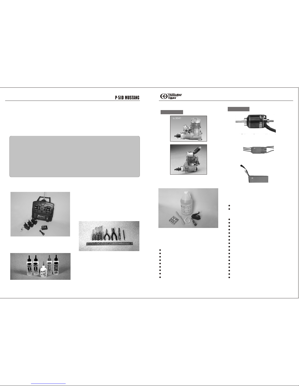
Engine The Thunder Tiger PRO-46 and F-54S are the
ideal engines for this airplane. These quiet running
engines are easy to start, require no special break in
periods, are very easy to maintain and will last for years.
Flight Equipment There are several “support” items
that you will need to purchase in order to get your engine
running and your plane in the air. These are listed at the
bottom.
ITEMS NEEDED
Introduction
Introduction.....................................2
Other Items Required.......................2
Items Need Check List.....................3
Parts Drawing..............................4-5
Pre-Assembly Notes......................6
Wing..........................................7-9
Tail...........................................10-11
.................................12Landing Gear
TABLE OF CONTENTS
A checklist is also provided on the next page which will make shopping for these items easier.
OTHER ITEMS REQUIRED FOR ASSEMBLY
Radio - A 4- channel radio with 4 standard servos is
required. Most lower priced 4-channel radios only
come with three standard servos so you may need to
purchase the fourth servo separately. If you fly with a
Nitro Power unit then 5 servos are required.
OBL Flight Equipment Needed Check List
2~3 APC 12X8E Propeller
4SIP 14.8V 4000mAh Lipo Battery Pack
Comprehensive Items Needed Check List
4-Channel Radio with 4 Standard Servos
Two Extended Cords(12"), one Y cord.
5-Minute Epoxy (4 ounces or so)
30-Minute Epoxy (4 ounces or so)
"Thin" Instant Adhesive (1/2 ounce)
"Thick" Instant Adhesive (1/2 ounce)
Hobby Knife and Blades
Epoxy Mixing Sticks and/or Brushes
Sandpaper (150 grit)
Masking Tape
Rubbing Alcohol
Paper Towels
Ruler
90 Degree Triangle
Waxed Paper
Fine-Point, Felt-Tip Pen
Misc. Household Tools
Drill and Bits (1/16", 5/64",1/8",1/4",5/16")
Nitro Flight Equipment Needed Check List
Foam Rubber Padding for the radio
Stick on Lead Strip for balancing the plane
3 or 4 Props (see engine instructions)
10%-15% Glow Fuel
Fuel Pump or Bulb
Electric Starter or "Chicken Stick"
Glow starter
Extra Glow Plug(s)
Silicon Tubing
OBL Power Unit ....................................13
Radio.................................................14
Canopy............................................15
Nitro Power Unit..............................16-18
Retract.....................................19-20
Decal.......................................21
Balance.............................................22
Your Next Choice ..............................23
Adhesives- You will need two types of adhesives for the
Tiger Trainer - Epoxy and Instant ( cyanoacrylate )
adhesives. We recommend that you purchase both 5minute and 30-minute epoxy to cut down on assembly
time, but you can get by with only 30-minute epoxy if time
is no important. You will also need a small bottle of both
"Thick" and "Thin" instant adhesive.
Battery: Recommend the use of a 14.8V 4000mAh Lipo
battery.
Charger: Select a quality field charger to charge the
battery.
OBL Power
Brushless Motor: If you would use electric motor
instead of a Nitro Engine then the OBL36/07-46A
( No. 2367 ) is a perfect choice to install on Tiger
Trainer OBL.
Controller: ACE BLC-40A ( No. 8027 ) is a perfect
controller that controlling OBL motor efficiently.
Congratulations on the purchase of our finest scale ARF. As the most successful fighters in WW2, a truly
incredible aircraft changed the war for allied air forces, the P-51D Mustang has enjoyed a reputation as
America' s favorite fighter. It is an aircraft not only combined speed with agility, but also had a long range
and powerful punch. Thunder Tiger is very proud to present the P-51D with its majestic flying capabilities
and great looks to all R/C hobbyists alike worldwide. Now every pilot can fly this most famous fighter
flying field tither by Nitro or Electric power.
No.9041
BLC-40A
Power Unit Required
Nitro power
No.9800
32
14.8V Lipo 4000mAh
Page 3
360cc (12oz)
AS6471 Fuselage
AS6472 Wing
Fuselage(1)
Left Wing(1)
Right Wing(1)
Wing Bolt(2)
Plywood
Wing Joiners(3)
Servo Case(2)
2X8mm Washer
Wood Screw(8)
Machine
Guns(2)
Retract Servo
Mount(4)
AS6473 Horizontal Tail
Horizontal Tail
CA Hinge(6)
CA Hinge(3)
AS6474 Vertical Tail
Vertical Fin/Rudder(1)
Captain Eddy(1)
No.3019
Captain Eddy
AS6475 Cowling
Cowling(1)
2X8mm Washer
Wood Screw(6)
3296 Wheel
Wheel(2)
AS6477 Canopy
Canopy(1)
Cockpit(1)
2X8mm Washer
Wood Screw(5)
AS6478 Linkages
Straight
Threaded End(2)
Clevis(4)
Z-Bend Threaded End 2)
3264 Fuel Tank
Tank(1)
Silicone
Tub(1)
Fuel
Stopper(1)
Straight
Nipple(1)
Cap(1)
Crank
Weight(1)
90-degree
Nipple(1)
AS6007 Scale Tail Gear
3X12mm
Wood Screw(1)
3X15mm
Wood Screw(1)
3X3mm
Set Screw(1)
AS6479
Control Horn
Control Horn(4)
Back
Plate(4)
2X20mm
Screw(4)
2X15mm
Screw(4)
PE0009 EZ Connector
1.5mm
Hex Wrench
EZ Connector(1)
3X3mm
Set Screw(1)
M2 Washer(1)
M2 Nut(1)
No.3278-Y Spinner
Spinner
Back Plate(1)
Spinner(1)
3X15mm Self-
Tapping Screw(4)
AS6458 OBL Motor Mount
6/32X18mm
Screw (4)
Sink Head
Screw (4)
OBL Motor Mount (1)
Main Gear
Wire
3X12mm
Wood Screw(8)
Landing
Gear Strap(4)
Collar(2)
3X5mm Screw(2)
Left Mount
Beam (1)
Right Mount
Beam (1)
No.3 03 Adjustable
Engine 1Mount
3X18mm
Wood Screw (4)
Engine Mount Plate(1)
AS6476 Decal
Fillet ( / , / )1L1R
1/4" Blind
Nut(2)
Scoop(1)
Radiator(1)
Landing
Gear Mount(2)
Fairing(1)
Elevator Joiner
Exhaust Vent(2)
Aileron Pushrod(2)
Inner Tube(1/L,1/S)
Guide Tube(1)
Throttle Pushrod (1)
Tail Gear(1)
Tail Wheel(1)
Collar(1)
Wheel Well(1/L,1/R)
Wheel Door(1/L.1/R)
Wheel Door Retainer
AS6481 Landing Gear
AS6480 Wheel Door
JE6767
JE6783
JE6784
JE6785
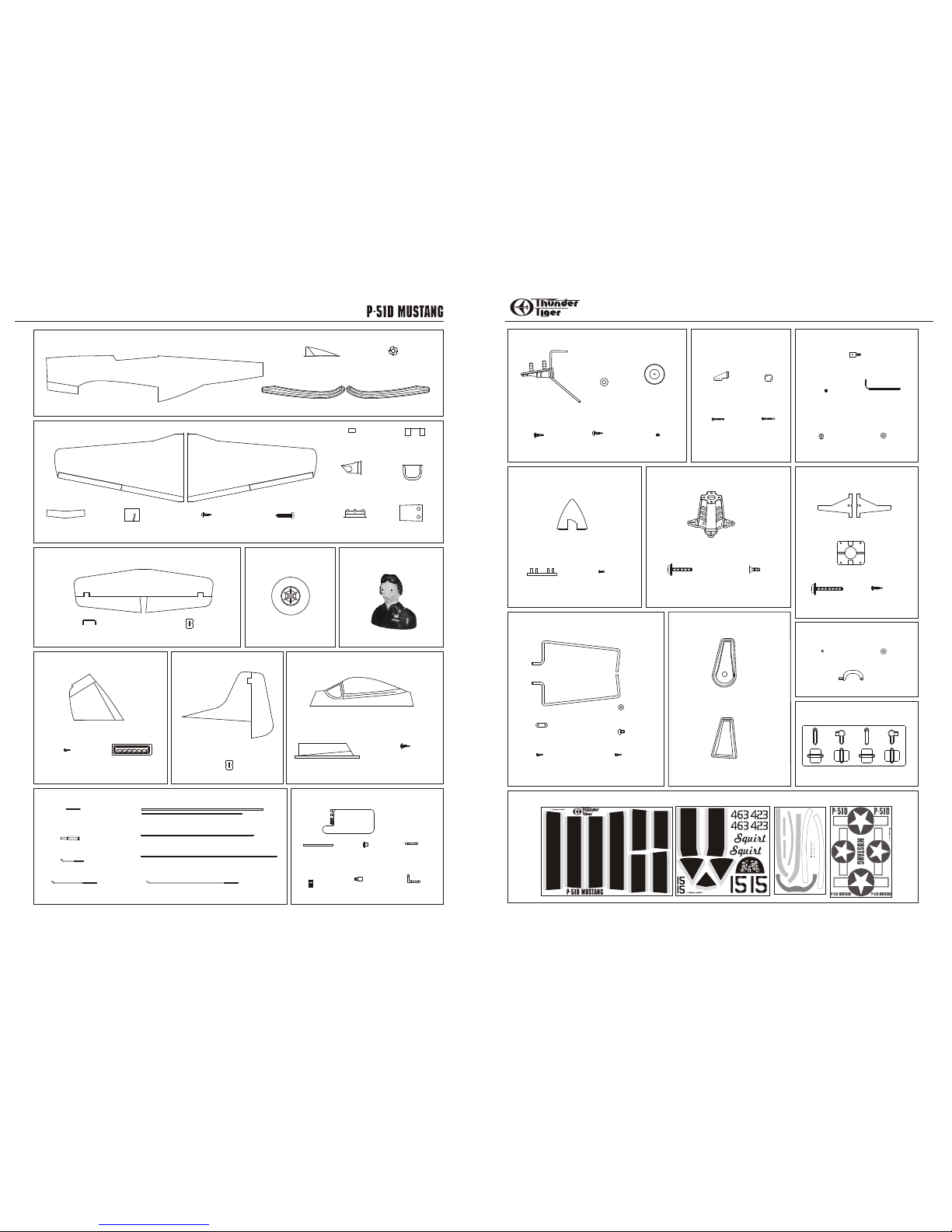
PARTS DRAWINGS PARTS DRAWINGS
Radiator Vent (1)
6/32X24mm
Screw (4)
Retract Gear Pushrod(2)
3X16mm Sink
Wood Screw(8)
AS6482 Wheel Door
Retainer
No.3023 Retract
Servo Link
Retract Servo Link(2)
E Clip(2)
M2 Nut(2)
54
Page 4
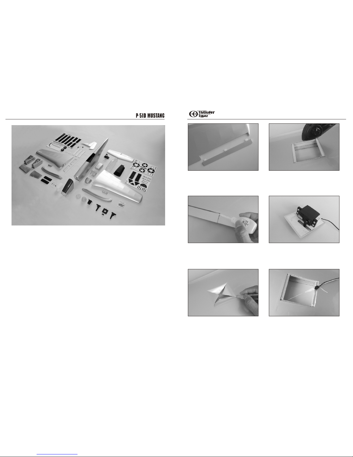
PARTS CHECK LIST WING
1. Remove aileron from the wing, CA three hinges on the
aileron.
2. Next attach the aileron on to the wing and apply CA to
the hinge area. Make sure the aileron is firmly secured
in place.
3. With the wing panel upside down, locate the servo well
and cut an X from corner to corner by using an hobby knife.
4. Use a sealing iron to tack down the covering inside
the servo well.
5. Secure the aileron servo in place, the hatch cover
shown is for left wing.
Connect servo to RX and turn on radio to make sure
servo is in neutral position then secure the control horn.
6. Attach the 12" aileron extension lead to the servo and
tape the connector to prevent from loosening. Locate a
string which is in the servo well, tie the string on the
connector and use mask tape to tape the connector so it
is easier to pass through the ribs.
Fuselage(1)
1/4" Blind Nut(2)
Fillet(1/L,1/R)
Left Wing(1)
Right Wing(1)
Retract Servo Mount(4)
Landing Gear Mount(2)
Scoop(1)
Fairing(1)
Plywood Wing Joiners(3)
Servo Case(2)
Wing Bolt(2)
Machine Guns(2)
Radiator(1)
Horizontal Tail
Elevator Joiner
CA Hinge(6)
Wheel(2)
Fuel Tank(1)
Silicon Tub(1)
Fuel Stopper(1)
Straight Nipple(1)
Cap(1)
Crank Weight(1)
90-Degree Nipple(1)
EZ Connector(1)
1.5mm Hex Wrench(1)
Radiator Vent (1)
Captain Eddy(1)
Main Gear Wire(1)
Landing Gear Strap(4)
Collar(2)
Wheel Well(1/L,1/R)
Wheel Door(1/L,1/R)
Wheel Door Retainer
Left Mount Beam(1)
Right Mount Beam(1)
Engine Mount Plate(1)
Wheel Door Retainer
M2 Washer(1)
M2 Nut(3)
2X20 Screw(4)
2X15 Screw(4)
3X5mm Screw(2)
3X3mm Set Screw(2)
6/32X18mm Screw(4)
6/32X24 Screw(4)
3X12mm Wood Screw(9)
3X15mm Wood Screw(1)
3X18mm Wood Screw(4)
2X8mm Washer Wood Screw(19)
3X15mm Self-Tapping Screw(4)
3X16mm Sink Wood Screw(8)
E Clip(2)
Retract Servo Link(2)
Canopy(1)
Cockpit(1)
Straight Threaded End(2)
Clevis(4)
Z-Bend Threaded End(2)
Aileron Pushrod(2)
Inner Tube(1/L,1/S)
Guide Tube(1)
Throttle Pushrod(1)
Tail Gear(1)
Tail Wheel(1)
Collar(1)
Control Horn(4)
Back Plate(4)
Vertical Fin/Rudder(1)
CA Hinge(3)
Spinner(1)
Spinner Back Plate(1)
OBL Motor Mount(1)
Sink Head Screw(4)
Cowling(1)
Exhaust Vent(2)
Retract Gear Pushrod(2)
Kit Contents:
76
Page 5

WING WING
7. Locate the servo wire exit hole and remove covering
on the top wing near wing root. Use Needlenose Pliers
or Tweezers to take the string out of the hole.
8. Drill four 1/16"(1.5mm) holes at four corners. Secure
the servo case in place with 2x8mm washer wood
screws.
9. Install the control horn in place with two 2x 15mm
screws.
10. Thread the clevis on the aileron pushrod then insert
the Z-bend end to servo horn and snap the clevis on
control horn. Adjust the aileron when in neutral position,
finally install a piece of silicone tube to hold clevis in
place firmly.
11. Locate the three Dihedral Wing Joiners and epoxy
the three Dihedral Joiners together.
12. Trial fit the joiners in each wing panel. If needed,
sand the edges lightly so that the joiner fits in each wing
half smoothly.
13. Mix up an ample amount of 30-min. Epoxy and apply
to the wing root ribs on each wing panel and Dihedral
Joiner and make sure you have plenty inside the wing
joiner slot. Slide the wings together, tape around the
joint, and wipe off any excess epoxy. Set aside for 1 hour.
14. Trial fit and center the wing in fuselage, make the
drill mark where is 1"(25mm) to the trailing edge and
center line.
15.Drill 1/8"(3mm) pilot hole first. Remove the wing then
enlarge hole up to 1/4"(6.5mm) on the wing.
16. Enlarge wing mount holes to 5/16"(8mm) then install
the blind nut from the bottom.
17. Trail securing the wing in place with two nylon wing
bolts.
18. Glue the radiator in place as well as the scoop.
98
1"
1"
Page 6

TAIL TAIL
19. Trim the fairing and CA the fairing in place.
20. Place the vertical fin in place then draw lines along
with the fin root on fuselage tail.
21. Cut the covering inside the line you drew about
1/32" (1mm) then peel away the covering.
22. Epoxy the vertical fin in place. Next cut away the
covering at the rear fuselage where stab located as well
as the covering of joiner slot.
23. Insert and center the horizontal tail in place. Draw
lines along the fuselage on the horizontal tail.
24. Remove the tail then carefully cut the line inside the
lines you draw about 1/32" (1mm). Peel away the
covering.
25. Epoxy the horizontal tail in place with the joiner
attached.
26.CA three hinges on each elevator.
27. Next attach the elevator on horizontal tail and
secure the elevator with CA glue. Make sure elevators
move freely.
28. Locate two holes at the bottom tail, install tail gear
then secure the tail gear with 3x15mm and 3x 12mm
wood screws.
29. CA three hinges on the rudder.
30. Trial fit the rudder on vertical fin and tail gear torque
rod. Apply CA glue when satisfied. Make sure the rudder
moves free after cured.
1110
Page 7

LANDING GEAR
OBL POWER UNIT
31. Cut the covering at the landing gear area as shown.
32. Locate the fixed gear mount and landing gear wire.
Insert the wire in place.
33. Trail fit the landing gear mount in place. Remove the
mount then apply epoxy and glue the gear mount firmly
in place. Iron the covering on the landing gear mount.
34. Use mounting strap as drilling guide then drill
5/64"(2mm) holes. Next secure the landing gear with
3x12mm wood screws.
35. Secure the wheel on landing gear with 3x5mm screw
and collar.
36. Trim the vacuum formed wheel door and retainer as
shown.
37. Secure the wheel door in place with the retainer by
using the CA glue.
38. Install the Outrunner (Thunder Tiger OBL36/07-46A
recommemended) on the OBL motor mount with four
sink head screws.
39. Install the OBL motor assembly on firewall with four
6/32 x18mm Washer Screw.
41.Install the propeller the spinner as shown then leave
2~3mm clearance between cowl and spinner backplate.
Next drill 1/16"(1.5mm) holes then secure the cowl with
six 2x8mm washer wood screws.
42. Trim the exhaust vent and CA it on the cowl.
Please skip to page 16 if Nitro Power Unit is used.
40. Trim the cool air inlet for best performance.
1312
Page 8

RADIO
CANOPY
44. In line with the pushrod outer tube, use control horn
as template to drill two 2mm holes then secure the
control horn with two 2x 20mm screws and backplate.
45. Locate the straight threaded end, Z bend threaded
end, inner tube and clevis then make sure one of inner
tube is 20-3/4" (527mm). Thread the Z-bend threaded
end first then insert the inner tube to the outer tube,
next thread the straight threaded end and the clevis.
Snap the clevis on the control horn.
46. Do the same procedure on elevator make sure the
inner tube is 17.5"(445mm) in length.
47. Install the servo in place as shown. The top servo in
the photo is elevator servo. The bottom one is rudder
servo. Adjust the pushrod when servos are in neutral
position.
48. Remove the Quick-Access Cover then secure the
Battery (14.8V 4000mAh recommended) with two
nylon ties. Refer the manual of Speed Control and
properly connect the Speed Controller, Receiver and
Battery. Protect the receiver with foam and secure the
receiver in fuselage. Insert a piece of foam after the
firewall, this is to prevent the battery from damage if
battery hit the screws when heavy landing or crash.
49. Cut away the covering on the rear radiator. If user
installs the engine instead of the electric motor then you
may skill this step.
50. Locate and trim the Radiator Vent then CA the vent
in place.
51. Route the antenna through the fuselage and exit
from the radiator vent. Tape the antenna to the tail as
shown.
52. Firstly apply instrument panel decal in place. Next
trim the cockpit along the molded lines then glue it in
the fuselage. Finally glue on the Cap'n Eddy .
53. Trim the canopy and apply canopy decal as shown.
54. Secure the canopy on fuselage with the decal.
43. Cut away the covering of elevator and rudder
pushrod exit holes on two side of rear fuselage.
Pull the outer tube out a little bit then CA the outer tube
in place.
1514
Page 9

56. CA the fillet to fuselage both at side and saddle.
Engine Installation
NITRO POWER UNIT
57. Locate the engine mount hardware, then install the
engine mount on firewall with four 6/32 x 24mm screws.
58. Measure from the firewall to the front of thrust
washer at 117mm( 4-9/16"). Mark the engine mounting
hole position on the engine mounts.
59. Secure the engine with four 3x 18mm wood screws.
60. Install the guide tube in the fuselage. Epoxy the tube
in place.
61. Install the throttle pushrod. You might need to screw
off the throttle lever first then attach to Z-bend throttle
pushrod end. Bend the pushrod for smooth movement.
62. Locate the fuel tank accessories then assemble the
fuel tank.
63. Install the fuel tank in place then secure it with nylon
tie band. Note orientation of the tank.
64. Secure the EZ connector on the servo horn with M2
washer and M2 nut. Make sure the connector is rotate
freely. Apply CA on M2 nut from loosening.
65. Secure the throttle servo in servo tray then install
the servo horn as shown. Adjust the throttle and secure
the pushrod with 3x3mm setscrew.
66. Use a piece of paper and draw the exhaust port
position on the paper.
You may need to enlarge drawing a little bit.
55. Refer to page 21 and apply all decal in place. Next
glue on the machine guns.
NITRO POWER UNIT
1716
Page 10

RETRACT
68. Trim away the drew area and trial fit the muffler.
69. Trial fit the muffler, next trim the cowl where might
contact carburetor.
70. Drill Glow Plug ignition hole, needle valve hole and
muffler securing hole for driver.
71. Install the propeller and spinner then secure the
cowl with six 2x8mm wood screws.
74. Locate a plywood template, place it on the landing
gear area then draw lines along the edge of the template
on the wing.
73. Cut away the covering at landing gear area.
75. Slightly cut away the covering of the line you drew.
You may find the laser cut lines on the planking.
76. Use hobby knife and remove the planking along the
laser cut lines.
77. Use hobby knife cut the wing root planking as shown.
At least 2"(5cm) in width for easy install the retract servo.
78. Locate four pieces plywood then CA two pieces
together, next glue this servo mount in place.
67. Next attach the cowl in place, make sure drive
washer is exposed about 2~3mm from the cowl. Make
marks on the cowl base on the drawing on the paper.
NITRO POWER UNIT
1918
72. Install the switch on fuselage, properly connect all
wires. Next wrap the receiver and battery with foam and
secure them in fuselage.
Page 11

RETRACT DECAL
81.Thread M2 nut and retract link to pushrod, next attach
to the servo horn. It might need time to adjust the length
and tension of the wire so retract gear could work
smoothly. Finally attached the E Clip and secure the
servo horn on the servo.
82.Trim and glue the wheel well in place
83. CA the wheel door retainer on the landing gear.
Make sure the wheel door accommodate to the wheel
well and retract works smoothly.
80. Connect the retract gear pushrod then thread the
pushrod to the retract servo then secure the retract gear
in place with four 3x16 sink screws.
Your P-51D is now ready to fly, carefully set up the
control throws and balance your plane well before the
flight; never take chances or rush fly your P-51D.
Refer to the photos and apply all decals.
7
11
3
1
9
6
5
2
4
8
10
12
13
1 2
3
4
5
6
7
8
9 10
11 12
13
1
2
Top
Bottom
2120
79. Install the retract servo as shown. Note the
orientation of the servo.
Page 12

No. 4573
Unlimited Pylon Racer
Specifications:
Wing Span: 673/4" (1720mm)
Length: 60" ( 1525mm)
Weight: 5500g ( 12 lbs.)
Engine: .90 2C, 1.20 4C req'd
Radio: 5~8ch 6~8 servos req'd
Specification:
Wingspan: 63" (1600mm)
Length: 55.5" (1410mm)
Weight: 10.5~11 lbs (4800–5000g)
Engine: .60~ .90 2C .91~1.20 4C
Radio: 5CH
Servo: 5 servos plus 1 retract servo
Unlimited Pylon Racer
The highly modified aircraft number 232 September Fury, owned and piloted by Mike Brown, qualified at a
blistering 468.266mph to take the third position at the 2002 National Championship Air Races(NCAR) and
established itself as the fastest Sea Fury in history. Thunder Tiger is very proud to present the legendary Sept.
Fury with its great speed to all R/C hobbyists alike worldwide. Fly it now! Experience the unlimited pylon racer of this
fastest Sea Fury!
World's Fastest Sea Fury!
John Penney piloted the popular Rare Bear and got first place in Unlimited Class qualify at 495.039 mph of the 10th
National Championships Air Race & Air Show, which was held in Reno Stead Field.
Thunder Tiger as official sponsor is licensed to produce this 1/6 Rare Bear. Pre-painted fiberglass fuselage and cowl,
scale details like panel line, aluminum spinner, and retract wells with gear door...etc. Now you can pilot this Rare
Bear 1/6 scale replica, the most popular unlimited pylon-racing machine from Thunder Tiger. Fly it low and fast to
experience the thrill and excitement of pylon racing. Go Bear !
Fly low, go fast and turn left
No. 4571
Control Throws
1/2"
3/8"
3/8"
Aileron-Low Rate
Aileron-High Rate
Elevator-Low Rate
Elevator-High Rate
Locate A Good Flying Site
Academy of Model Aeronautics
5151 East Memorial DR
Muncie, IN 47302-9252
www.modelaircraft.org
A Note On Batteries
Congratulations
Set the control throws as followings for a starting point. After you
familiar with its flying characteristics then these control throw can
be tailored to fit your flying style.
IMPORTANT - Do not attempt to fly your model before
completing this very important section. A model that is not
properly balanced will be unstable and could cause serious
damage and/or injury. Adjust the battery location or add
weight as needed to achieve level balance.
Center of Gravity
The batteries are the heart of your radio system. Make sure
you have fully charged batteries! With recharge-able
batteries, follow the manufacturers instructions to make
sure the batteries are fully charged, especial the first time
the radio is used. We would recommend you use larger
capacity(1000mAh NiMH battery for Nitro version, 4000mAh
Lipo battery for Electric version ) if you use high performance
servos as they will draw more current than ordinary servos.
If there is not a chartered club field in your community,
you will need to find a large area free of obstructions, and
has a smooth grass or asphalt surface to be used as a
runway. For safetysake, it should be located well away from
houses, buildings, schools, power lines and airports. If you
will be flying within 6 miles of an airport, you should check
with the airport manager before flying your model.
Generally, the best place to fly your model is at an AMA
(Academy of Model Aeronautics) chartered club field. Your
local hobby dealer can tell you if there is such a club in your
area or write the AMA for information. It is also a good idea
to join this organization before flying your model since they
offer liability insurance that can protect you if your model
causes damage or injury to others.
Measure the C.G. while plane is dry. The balance point is
about 4 1/2"(114mm) behind the leading edge at wing root .
1"
Rudder-Low Rate
Rudder-High Rate
1/2"
4-1/2"(114mm)
Pick up model at arrows.
Now that you have completed the assembly of your P 51D we eel that you have a very capable and good
looking sports scale plane. We hope that you will enjoy
this model and get many hours of flying pleasure from its
use. Thank you for purchasing this P-51D from Thunder
Tiger and we look forward to providing you with other
great R/C products in the future.
3/4"
3/4"
1"
3/4"
3/4"
1"
1"
YOUR NEXT CHOICE
BALANCE
2322
 Loading...