


INSTRUCTION MANUAL
INSTRUCTION MANUAL
組裝說明書
組裝說明書
No.4712
This radio control model car is not a toy! Before beginning assembly, please
read this manual thoroughly.
本產品為高性能模型非一般玩具,組裝與操作前請詳閱本產品說明書。
The contents are subject to change without prior notice due to product
improvements and specificatrion changes.
本套件所附之零件可能跟圖示有所差異。因產品後續之設計研發或功能不斷改善之原
因,我們將保留產品規格變更權力,不再另行通知使用者。

CONTENTS
Introduction
Thunder Tiger
INTRO & CAUTION / 簡介與注意事項
OTHER ITEMS REQUIRED / 其餘必須配件
ASSEMBLY / 組裝步驟
MAIN ROTOR / 主旋翼機構組裝
LINKAGE ROD INSTALLATION / 連桿組裝
MAIN FRAME ASSEMBLY / 本體組裝
TAIL UNIT ASSEMBLY / 尾管組裝
TAIL BOOM BRACKET SET / 尾管固定座組裝
ELECTRIC SYSTEM / 電子系統
CANOPY ASSEMBLY / 機艙罩組裝
MAIN ROTOR BLADE ASSEMBLY / 主旋翼組裝
INTRODUCTION OF E-CCPM CONTROL SYSTEM / E-CCPM 控制系統介紹
MOVEMENT OF 120°E-CCPM SYSTEM / E-CCPM 120°說明
SERVO CONNECTING / 伺服機連結
BASIC CONCEPT OF ADJUSTMENT / 基礎設定與調整
SETTING UP OF LINKAGE / 連桿設定
2
4
5
6
12
13
17
21
23
27
28
29
30
31
32
35
SETTING UP MAIN ROTOR COLLECTIVE PITCH ANGLE / 主旋翼螺距設定
SETTING UP DATA FOR YOUR REFERENCE / 設定參考值
USING OF LI-PO BATTERY / 鋰聚電池使用注意事項
TROUBLE SHOOTING / 問題排除
HELI ACCESSORIES / 選購配件
BALL LINK REAMER (ø3.8MM) 球頭絞刀
ONE WAY BEARING RELEASER 單向軸承退出器
BLADE BALANCER 主旋翼平衡器
TRAINING GEAR 直昇機練習架
SPARE PARTS / 零件表
OPTION PASTS & ACCESSORIES / 選購零配件
EXPLODED VIEW / 爆炸圖檢索
SPECIFICATION & FEATURES / 規格表 & 特色
-1-
36
38
40
40
42
42
42
43
46
47
54
56
59

INTRODUCTION / 簡介
Thank you for purchasing the Thunder Tiger mini Titan E325 V2 electric R/C helicopter. This new helicopter
is the latest innovation by Thunder Tiger. It has the perfect combination of flying stability and the agility for
3D flying. This helicopter is an excellent choice for flying enthusiasts like you. For convenient assembly
and safe operation of the helicopter, please read the instructions carefully. Retain the user manual in case
you need it for any information or reference.
感謝您購買雷虎科技小型電動直昇機 mini Titan E325 V2 產品,本項產品為雷虎科技全新開發機種,兼具高度穩定性
與3D飛行特性,是熱衷小型電動直昇機的您不可錯過的選擇。請於使用本產品前詳盡閱讀使用手冊,以利於組裝工作
順暢進行與安全操控本產品。請妥善保存使用說明書,以利後續調整與維修參考用途。
CAUTION / 警告
1. R/C models are not toys. This product is a high-precision flying machine. Possibilities of unexpected
crashes may occur due to electronic interference, incorrect operation, or poor mechanical maintenance.
Although it is a small-sized helicopter, the rotor blades rotate at high speeds, which may cause serious
damage, injury, or death if the model hits people or property. Therefore, extreme caution must be
exercised during operation.
2. Thunder Tiger ensures parts packaged in this product is of the highest quality. However, after assembly
and usage, parts damaged due to wear or misuse will not be replaced under any circumstances. If you
have any questions regarding its operation and repair, Thunder Tigers service agents are able to
provide free technical guidance.
3. This product is only recommended for users ages 16 and up. Because flying a R/C helicopter is difficult,
beginners must receive guidance and supervision from experienced pilots to minimize unexpected danger.
Practice in spacious areas, far away from obstacles such as buildings, trees, electrical towers, or crowds.
4. To decrease the cost of repair and maintenance for beginners, it is recommended to fly the helicopter
with a practice rack and to learn basic flying skills with a computer R/C flying simulator. (Crashes in
simulators are free to repair!)
1. 本項遙控直昇機產品並不是玩具,是一項結構精密、高專業度模型產品,如果未經正確組裝與操控,將可能對操控
者或其他人造成身體傷害。使用者必須了解,若未確實進行飛行前安全檢查或操控不當,而造成人員受傷或物體損
壞,使用者必須負起法律責任。
2. 本產品由高品質零組件組成,雷虎科技對於安裝過程、使用過後..等人為因素造成損壞事件不負損壞賠償之責。如您
需要本產品相關組裝、調整或其他協助,可與雷虎科技全省經銷商聯繫。
3. 本項產品禁止十六歲以下青少年與孩童使用。強烈建議初學者應取得技術支援後再進行飛行,以避免危險發生。請
於空曠地區操控本產品,並避免於建築物、樹木、電塔..等障礙物區域飛行。
4. 建議初學者可安裝練習架或透過電腦模擬軟體練習,可達到實際練習效果與符合經濟效益。
AMA INFORMATION / 特別注意事項
Operating a model helicopter requires a high degree of responsibility and skill. If you are a newcomer to the
hobby, it is best to seek help and guidance from accomplished model helicopter pilots. This will greatly
speed up the learning process and have you flying successfully in a reasonable amount of time. We also
would strongly urge you to join the Academy of Model Aeronautics. The AMA is a non-profit organization
that provides its members with a liability insurance plan as well as monthly magazine entitled Model Aviation.
All AMA charter aircraft clubs require all pilots to hold a current AMA sporting license prior to operation of
their models at club fields. For further information, contact the AMA at:
Academy of Model Aeronautics
5151 East Memorial Drive
Muncie, IN 47302
(317) 287-1256
操控遙控直昇機對於飛行安全要求極高,需要高度的負責任態度配合,以及較高的操控技巧。如果您是一位初學者,
建議您必須向當地專業模型經銷商,或是遙控直昇機相關組織以及經驗豐富的玩家尋求相關協助,以獲得您所需要的
訊息以及專業知識。如此可有效協助您縮短學習的時間,更容易學會遙控直昇機的組裝、設定與操控技巧。
-2-

FLIGHT SAFETY CHECKLIST / 飛行前安全確認工作項目
1. Make sure that the transmitter battery is fully charged before flying.
2. Make sure all control surfaces are operated properly before flying.
3. Do a range check of the radio before the first flight. The electronic equipment must operate properly
at a range of at least 5 meters (18 ft) even with the transmitter antenna collapsed.
4. Make sure there are no other pilots using the same radio frequency with yours and that there are no
other radio interference on your frequency.
5.
Be sure to turn on the transmitter first with the throttle stick in the idle position. Plug the battery into the
ESC last.
6. The main rotor and the tail rotor spin at very high RPM. Make sure nothing can come in contact with
the rotor blades during flight.
7. Always maintain a safe distance from the helicopter during flight.
8. Never fly the helicopter in the rain or in excessive wind conditions.
9. Always operate and fly the helicopter in a safe and responsible manner.
10. Never fly the helicopter over other pilots, spectators, cars or anything that could result in injury or
property damage.
1. 確認接收機與發射機電池,均已確實充電完成。
2. 確認所有操控介面運作順暢。
3. 確認無其他無線電波干擾,且不與其他同好同時使用相同頻率。
4. 確實將油門搖桿放置於低速,再將發射機電源開啟,然後再將電池接上。
5.
確認遙控器發射器與接收機工作正常,將機體放至於距離5公尺外,確認遙控器是否正常,機體控制動作是否正確。
6. 主旋翼與尾旋翼轉速相當高,運轉時須避免任何障礙物與旋翼接觸。
7. 飛行時,需與遙控直升機保持安全距離。
8. 勿於下雨天或是強風的狀態下操控遙控直升機。
9. 請以安全為第一考量,並以高度負責任的態度參與遙控直升機活動。
10. 禁止於人群、車輛..或任何其他障礙物上方飛行遙控直升機,避免意外發生。
POST FLIGHT INSPECTION / 飛行結束安全檢查事項
1. Inspect the model thoroughly to insure no parts have come loose or become damaged during the flight
and landing. Replace damaged parts and tighten loose screws before flying again.
2. Clean the helicopter body.
3. Lubricate all moving parts to ensure smooth operation for the next flying.
4. Replace any worn ball links and damaged bearings.
5. Store the model in a cool, dry place. Avoid putting it under direct sunlight or near a source of heat.
Following these simple rules will allow you to enjoy the thrill of model helicopter flying for many years.
1. 飛行結束後確認機體所有的零件與螺絲是否有損壞或鬆動,更換損壞零件與確實固定鬆動的螺絲。
2. 機體清潔乾淨。
3. 檢查所有活動零組件是否運作順暢,以利下次飛行。
4. 更換所有鬆動的連桿、接頭,以及損壞的軸承。
5. 將機體存放於陰涼通風處,避免機體放置於陽光直射處或接近熱源。
確實執行上述幾項簡單的步驟,將可確保您的愛機維持數年的壽命!
CAUTION / 注意事項
When the model has crashed, inspect the flybar, rotor shaft and the blade spindle to make sure they are
not bent. If any item is damaged, it must be replaced with a new part to ensure safe operation. Do not
glue any broken or damaged plastic parts. Do not repair broken rotor blades. It is very important to
inspect the motor, speed control and the battery.
Always inspect the following items:
Gears, Ball links, Link rods, Bearings, Main shaft, Flybar, Spindle, Tail boom and support, Fins, Tail rotor
shaft, Belt, Main blades, Tail blades, the Motor, the Speed control and the Battery.
機體一但發生墜落事件,請確實檢查平衡桿、主軸、橫軸是否有彎曲變形,如果有任何的損壞,請立即更換原廠新
的零組件,確認機體操作安全!切勿使用任何接著劑嘗試黏合塑膠零件;請勿使用修復過的主旋翼。馬達、速控器
、電池的安全檢查工作亦相當重要。
發生機體墜落事件後,請確實檢查下列項目:
齒輪組、球頭連桿、連桿頭、軸承、主軸、橫軸、尾軸、平衡桿、平衡片、尾管、尾管支撐架、垂直與水平尾翼、
尾驅動輪、皮帶、主旋翼、尾旋翼、馬達、速控器、電池。
-3-

OTHER ITEMS REQUIRED / 另購裝備
RADIO SET
Transmitter
(helicopter type only,
6 or more channels)
發射機(6動以上直昇機用)
POWER SYSTEM
Li-Po Battery Speed Controller Brushless Motor Battery Charger
鋰聚合物電池
遙控器組
Receiver
接收機
電子類裝備
速控器 無刷馬達 充電器
Micro Servos
(Control Surface x3,
Rudder Servo x1)
伺服機 x3、尾舵伺服機 x1
Gyro
陀螺儀
TOOLS REQUIRED FOR ASSEMBLY
Screw Driver Needle Nose Pliers Ball Link Pliers
螺絲起子
Hobby Knife CA Glue Threadlocking Grease
模型專用美工刀
尖嘴鉗 連桿專用鉗 斜口鉗 剪刀
快乾膠 螺絲防鬆膠 潤滑油
組裝工作所需工具
Nipper
Scissors
Hex Wrench
六角板手
Epoxy
環氧樹指
(A、B膠)
Rubber Band Two-Sided Rubber
橡皮筋 雙面膠
-4-

MANUAL FORMAT / 說明書使用方式
How to read the instruction manual?
說明書導讀
A: Indicates the assembly step number and the parts bags that are to be assembled.
B: Displays actual size drawings, and part quantities used.
C: All parts, except screws, are identified by its order numbers. When purchasing spare parts, identify the part
required and cross reference this to the spare parts list in the end of this maunal, which shows the purchasable
spare parts and the corresponding order numbers.
D: This instruction manual uses several symbols. Pay careful attention to them during construction. Details are given at
the bottom of each page.
A: 顯示組立步驟及需組立之零件包順序
B: 零件實際對照尺寸及使用數量
C: 請比對零件形狀以及後附零件料號對照圖示找出需求零件料號
D: 操作說明符號可更有效協助組裝者使用此說明書,請依說明書符號指示進行組裝步驟
Example 說明範例
Bag A
No.
1
2
3
Material No.
BK1502
BK1086
HML2
Main Rotor-5 /
Description
HARDENED MAIN SHAFT
SOCKET SCREW M2×14
M2 NUT
主旋翼機構組裝
名稱
高強度主軸
內六角半牙螺絲
M2
螺帽
M2×14
-5
Qty
1
1
2
BK1086
SOCKET SCREW M2×14
內六角半牙螺絲
M2×14
HML2
M2 NUT
M2
螺帽
C
Step 1 / 步驟一
1. Insert the main rotor head set into the Main Shaft. Note the end with a
hole of the Main Shaft has to insert into the Hub.
2. Line up the holes on the Main Shaft & Hub.
3. Insert the Socket Screw (M2 x 14, #2) through the Hub and apply a
drop of threadlocking to screw it with the Nut.
1. 將主軸穿過組裝完成的主旋翼頭組。
2. 對正主軸及固定座上孔位。
3. 以半牙內六角螺絲穿過固定座及主軸後,
套上螺帽並使用適量防鬆劑固定。
B
B
The hole should point up.
請注意,有孔位的一端應朝上
A
C
(3)
(2)
T22
D
(1)
SYMBOLS USED THROUGHOUT THE MANUAL / 符號說明
The parts in the mini Titan E325 V2 are packed according to each major assembly steps. The part number and quantity
are always shown in the square box on each page. As good practice, only open up the bag that you need for the paticular
assembly.
零件均依照組裝步驟包裝,請依照組裝程序,逐一開啟零件包,避免零件遺失。
Note / 注意
Note / 注意
Assembly drawings will contain icons that indicate use of
Threadlocker or CA glue as needed.
Examples of the icons are as right shown:
請依組裝步驟圖示,使用防鬆膠或接著劑。
圖示範例如右:
T22 THREADLOCKER / 螺絲防鬆膠
CA CA GLUE / 快乾膠
Apply CA Glue
使用快乾膠黏合
Apply threadlocker
使用螺絲防鬆膠
Assemble as many times as specified
依指示組裝所需數量
Assemble left and right side the same way
左右側組件相同
Assemble in right order
依標示順序組裝
Cut off shaded portion
依標示部分裁切
Ensure smooth, non-binding movement when assembling
確認組件靈活度
Drill holes with the specified diameter
依標示尺寸鑽孔
Must be purchased separately
改裝品需另購
-5-
Cut off excess
裁剪多餘部分
Apply grease
使用潤滑油膏(黃油)
Pay close attention here
注意組裝步驟
Hint
組裝提示

Bag A
Main Rotor-1 /
主旋翼機構組裝
-1
No.
Material No.
1
BK2615
2
BV1403
BK1456
COLLAR, d2×D3×2.7t
軸環, d2×D3×2.7t
HNU2-6Z
SHOULDER SCREW M2x6
圓頭十字軸套螺絲M2×6
Description
MATEL MAIN ROTOR HUB SET
METAL SEESAW HUB
名稱
金屬主旋翼固定座組
金屬穩定桿固定座組
Qty
1
1
No.
Material No.
3
BK1456
4
HNU2-6Z
Step 1 / 步驟一
1. Slide the Metal Seesaw Hub into the Main
Rotor Hub.
2. Note the orientation of the Metal Seesaw
Hub.
1. 將主旋翼固定座穿過穩定桿固定座。
2. 注意穩定桿固定座安裝方向。
(1)
Description
COLLAR, d2×D3×2.7t
SHOULDER SCREW M2x6
名稱
軸環, d2×D3×2.7t
圓頭十字軸套螺絲M2×6
Qty
Step 2 / 步驟二
1. Rotate the Metal Seesaw Hub toward for
90 degree.
2. Note the orientation of the Chamfer on the
Metal Seesaw Hub.
1. 90度旋轉穩定桿固定座。
2. 注意金屬穩定固定座倒角方向。
chamfer / 倒角
2
2
(2)
Step 3 / 步驟三
Fit the Collar into the bearings, tighten
the screws and ensure the Metal
Seesaw Hub runs effortlessly.
如圖示,鎖緊固定螺絲,並確認穩定桿固
定座能自由活動。
(4)
(3)
(4)
chamfer
倒角
Completed View
組裝完成
T22
T22
(3)
-6-
Bag A
Main Rotor-2 /
主旋翼機構組裝
-2
No.
Material No.
1
BV1404
2
BK1480
3
BK1203
BK1480
COLLAR, d2×D3×5.6t
軸環
, d2×D3×5.6t
BK1203
Linkage Ball(ø3.8)
連接頭
(ø3.8)
HSP16-6N
Countersunk Screw M1.6×6
圓頭十字螺絲
BK1481
FLAT WASHER d2xD3.7x0.5t
墊片
d2xD3.7x0.5t
Description
METAL MIXING LEVER
COLLAR, d2×D3×5.6t
LINKAGE BALL(ø3.8)
M1.6×6
名稱
金屬控制搖臂組
, d2×D3×5.6t
軸環
連接頭
(ø3.8)
Qty
2
2
4
No.
Material No.
4
HSP16-6N
5
BK1481
6
HNU2-9Z
Description
COUNTERSUNK SCREW M1.6×6
FLAT WASHER d2xD3.7x0.5t
SHOULDER SCREW M2x9
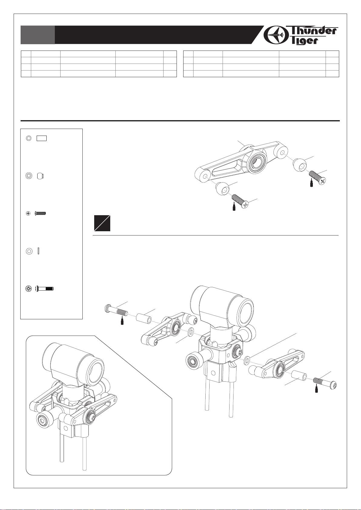
Step 1 / 步驟一
Secure the Linkage Balls to the Mixing Lever.
依圖示,安裝控制臂球頭,並適量使用螺絲防鬆劑。
(1)
(3)
T22
Assemble left and right side the same way
L
左右側組件相同
R
Step 2 / 步驟二
1. Secure the Metal Mixing Lever to the Metal Seesaw Hub.
2. Make sure the Metal Mixing Lever runs effortlessly.
1. 將金屬控制臂安裝於金屬穩定桿固定座,並適量使用螺絲防鬆劑。
2. 確認控制臂能自由動作,無干涉及過鬆現象。
(4)
名稱
圓頭十字螺絲
墊片
圓頭十字軸套螺絲
M1.6×6
d2xD3.7x0.5t
T22
M2×9
(3)
Qty
4
2
2
(4)
HNU2-9Z
SHOULDER SCREW M2x9
圓頭十字軸套螺絲
M2×9
(6)
(2)
T22
Completed View
組裝完成
(5)
(2)
(5)
(6)
T22
-7-

Bag B
Main Rotor-3 /
主旋翼機構組裝
-3
No.
Material No.
1
BK1499
2
BK1500
3
BK1203
4
HSP16-6N
Description
M. FLYBAR C. ARM-1
M. FLYBAR C. ARM-2
LINKAGE BALL(ø3.8)
COUNTERSUNK SCREW M1.6×6
Step 1 / 步驟一
1. Secure the Linkage Ball to the Metal Flybar
BK1203
Linkage Ball(ø3.8)
連接頭
(ø3.8)
HSP16-6N
Countersunk Screw M1.6×6
圓頭十字螺絲
HME3-3B
SET SCREW M3×3
無頭內六角螺絲
L
R
M1.6×6
M3×3
Assemble left and right side the same way
左右側組件相同
Contorl Post.
2. Assemble the Metal Flybar Control Post and
the Metal Flybar Control Arm.
1. 牢固的將球頭安裝於金屬穩定翼轉臂柱上。
2. 將金屬穩定翼轉臂柱及金屬穩定翼臂裝配完成。
(4)
名稱
金屬穩定翼轉臂
金屬穩定翼轉臂
連接頭
(ø3.8)
圓頭十字螺絲
M1.6×6
(2)
T22
-1
-2
(3)
Qty
2
2
2
2
T22
No.
Material No.
5
BK1410-1
6
HME3-3B
7
BK1413
(1)
M3×3
)
Qty
1
2
2
Description
SUS FLYBAR ROD
SET SCREW M3×3
FLYBAR PADDLE(GREEN LIGHT)
名稱
不鏽鋼穩定桿
無頭內六角螺絲
穩定翼(綠
Step 2 / 步驟二
1. I
nsert the Flybar Rod through the Metal Flybar
Control Arms & the Metal Seesaw Hub.
2. Ensure the Flybar Rod have equal
protrusion from each side of the Metal
Flybar Control Arms.
3. Line up the holes of the Metal Flybar
Control Arms and the flat spot of the Flybar
Rod, and then screw the Metal Flybar
Control Arms & the Flybar Rod tightly.
1. 將穩定桿穿過金屬穩定翼控制臂、金屬穩定桿固
定座和金屬旋翼固定座。
2. 確認穩定桿凸出金屬穩定翼控制臂兩側等距。
3. 對正金屬穩定翼控制臂上鎖固孔與穩定翼桿上平
面凹槽後,再鎖緊螺絲。
T22
(6)
(6)
T22
(7)
Note 1 / 注意 1
70mm 70mm
Note 2
注意 2
CA
83mm
54mm
(5)
83mm
CA
(7)
Step 3 / 步驟三
1. Thread the Paddles onto the Flybar Rod, equal the length to the
Flybar Control Arms of each side.
2. Ensure the leading edges of the Paddles are toward the same side to
the Metal Flybar Control Posts.
3. Line up the Paddles with the Flybar Control Arms.
1. 旋上穩定翼於穩定翼桿上,確認兩側的穩定翼至控制臂距離相等。
2. 確認穩定翼前緣與穩定翼控制轉臂方向相同。
3. 對正穩定翼與穩定翼控制臂呈水平狀態。
-8-

Bag B
Main Rotor-4 /
主旋翼機構組裝
-4
No.
Material No.
1
BK1203
2
HSP16-6N
3
BV1402
4
BK0906
BK1203
LINKAGE BALL(ø3.8)
連接頭
(ø3.8)
HSP16-6N
COUNTERSUNK SCREW M1.6×6
圓頭十字螺絲
BK1079
COLLAR
軸環
HMO26
FLAT WASHER d2.6
華司
d2.6mm
HMC26-8B
SOCKET SCREW M2.6×8
內六角螺絲
Description
LINKAGE BALL(ø3.8)
COUNTERSUNK SCREW M1.6×6
METAL ROTOR GRIP
FEATHERING SHAFT
M1.6×6
M2.6×8
名稱
(ø3.8)
連接頭
圓頭十字螺絲
金屬旋翼轉座組
主旋翼固定軸
M1.6×6
Qty
No.
Material No.
5
2
2
2
1
BK1900
6
BK1079
7
HMO26
8
HMC26-8B
Description
FLAP DAMPER
COLLAR
FLAT WASHER d2.6
SOCKET SCREW M2.6×8
名稱
避震墊圈
軸環
d2.6mm
墊片
內六角螺絲
M2.6×8
Qty
Step 1 / 步驟一
1. Secure the Linkage Balls to the Main Rotor Grips.
2. Insert the Flap Damper into the Main Rotor Hub.
3. Insert the Feathering Shaft through the Flap Dampers & the Main Rotor Hub with some
amount of silicon oil or Vaseline. Center the Feathering Shaft in the Main Rotor Hub.
4. Apply Locitite on the Socket Screw (M2.6x 8, #8),and then secure the Main Rotor Grips
on the Feathering Shaft with bearings & washers tightly.
1. 將連桿接頭固定於主旋翼夾座。
2. 將旋翼橫軸避震套環置入主旋翼夾座內。
3. 可塗抹些許矽膠油脂或凡士林於旋翼橫軸避震套環上,以便安裝。
4. 依圖示,組裝金屬主旋翼固定座,使用M2.6X8內六角螺絲鎖入橫軸時需使用螺絲防鬆膠。
Note / 注意
The radial & thrust bearings inside the Main
Rotor Grips are factory pre-assembled. The
below drawing is for your reference.
止推軸承及滾珠軸承已由原廠組裝完成,參考如
下圖示:
(4)
(5)
(6)
(2)
T22
(1)
(3)
(7)
(8)
2
2
2
2
Diagram for Thrust Bearing Assembly
止推軸承安裝示意圖
Large Internal
Diameter
always go toward the
Main Rotor Hub
內徑較大的一側,面向
主旋翼中心座組。
Small Internal
Diameter
always go toward the
Blade
內徑較小的一側,面向
主旋翼組。
(2)
Checking Tips: >
轉動角度: >
(轉動角度大者,內孔大;轉動角度小者,內孔小)
T22
Completed View
組裝完成
-9-

Bag B
Main Rotor-5 /
主旋翼機構組裝
-5
No.
Material No.
1
BK1502
2
BK1086
3
HML2
BK1086
SOCKET SCREW M2×14
內六角半牙螺絲
HML2
M2 NUT
M2
螺帽
Description
HARDENED MAIN SHAFT
SOCKET SCREW M2×14
M2 NUT
M2×14
M2×14
Qty
1
1
2
名稱
高強度主軸
內六角半牙螺絲
M2
螺帽
Step 1 / 步驟一
1. Insert the main rotor head set into the Main Shaft. Note the end with a
hole of the Main Shaft has to insert into the Hub.
2. Line up the holes on the Main Shaft & Hub.
3. Insert the Socket Screw (M2 x 14, #2) through the Hub and apply a
drop of threadlocking to screw it with the Nut.
1. 將主軸穿過組裝完成的主旋翼頭組。
2. 對正主軸及固定座上孔位。
3. 以半牙內六角螺絲穿過固定座及主軸後,
套上螺帽並使用適量防鬆劑固定。
(3)
T22
(2)
Note / 注意
The hole should point up.
請注意,有孔位的一端應朝上
(1)
Step 2 / 步驟二
Screw a second Nut with a drop of threadlocking to prevent the Socket Screw coming loose.
於固定螺帽外側再鎖上一顆螺帽,使用適量防鬆劑固定,防止鬆脫。
-10-
(3)
T22
Bag C
Main Rotor-6 /
主旋翼機構組裝
-6
No.
Material No.
1
BV1406
2
BK1014
3
HSP17-7N
4
BK1480
5
HSP16-6N
6
BK1203
HSP17-7N
Countersunk Screw M1.7×7
圓頭十字螺絲
HSP16-6N
Countersunk Screw M1.6×6
圓頭十字螺絲
BK1480
COLLAR, d2×D3×5.6t
軸環
d2×D3×5.6t
BK1481
FLAT WASHER d2xD3.7x0.5t
墊片
d2xD3.7x0.5t
Description
M. FLYBAR C. LEVER
WASHOUT LINKAGE
COUNTERSUNK SCREW M1.7×7
COLLAR, d2×D3×5.6t
COUNTERSUNK SCREW M1.6×6
LINKAGE BALL(ø3.8)
M1.7×7
M1.6×6
名稱
金屬穩定翼控制臂組
連接座
圓頭十字螺絲
軸環
圓頭十字螺絲
連接頭
M1.7×7
d2×D3×5.6t
M1.6×6
(ø3.8)
Qty
2
2
2
2
2
2
No.
Material No.
7
BK1481
8
HNU2-9Z
9
BV1405
10
BV1419A
11
BK1020
12
HME3-3B
Description
FLAT WASHER d2xD3.7x0.5t
SHOULDER SCREW M2x9
METAL WASHOUT BASE SET
METAL Swashplate
MAIN SHAFT LOCK RING
SET SCREW M3×3
名稱
墊片
圓頭十字軸套螺絲
金屬控制臂座組
金屬十字盤
止擋圈
無頭內六角螺絲
d2xD3.7x0.5t
M2×9
M3×3
Qty
2
2
1
1
1
1
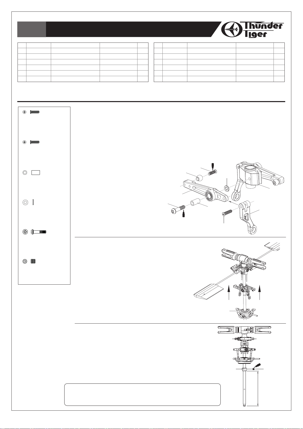
Step 1 / 步驟一
1. Secure the Washout Linkage to the Metal Flybar Control Lever and ensure the Washout
Linkage runs effortlessly.
2. Secure the Linkage Balls to the Metal Flybar Control Lever. The inner hole on the lever is for
novice, and the outer hole is for 3D flying.
3. Secure the Metal Flybar Control Lever to the Washout Base.
4. Make sure the Metal Flybar Control Lever runs effortlessly.
1. 將連接座固定於金屬穩定桿控制臂上,需確認轉動順暢。
2. 將球頭鎖入穩定桿控制臂,內孔適合初學者,外孔則適合
3D特技飛行。
3. 將金屬穩定桿控制臂鎖上固定於控制臂座上。
4. 確認金屬穩定桿控制臂轉動順暢。
(5)
(6)
T22
(7)
(9)
(1)
(8)
(4)
T22
(2)
(3)
HNU2-9Z
SHOULDER SCREW M2x9
圓頭十字軸套螺絲
HME3-3B
Set Screw M3×3
無頭內六角螺絲
M2×9
M3×3
Step 2 / 步驟二
1. Slide the metal washout set into the Main Shaft,
and ensure the pins of the Metal Main Rotor Hub
go through the slots of the Metal Washout Base.
2. Slide the Metal Swashplate into the Main Shaft.
Attach the Washout Linkage to the inner linkage
balls of the Metal Swashplate.
1. 將控制臂組穿過主軸,並將主旋翼固定座插銷穿過控制
臂中心座。
2. 將十字盤穿過主軸,將控制臂座組連桿與十字盤內盤連
桿頭連接。
Step 3 / 步驟三
Slide the Main Shaft Lock Ring and fix by a Set Screw
with a drop of threadlocking.
將主軸固定套環穿過主軸並用螺絲固定。
(10)
(11)
T22
(12)
Note / 注意
The length from the end of the Min Shaft to the Lock Ring is 70mm.
固定套環安裝位置為距離主軸底部約70mm處(如圖示)。
-11-
70mm
Bag D
Linkage Rod Installation /
連桿組裝
No.
Material No.
1
BK0932
2
BK1063
3
BK0922
BK0922
Ball Link d3.8x12mm
單頭連接桿
BK0932
Ball Link d3.8x10mm
單頭連接桿
Scale=1:1
(unit:mm)
Description
BALL LINK d3.8x10mm
LINKAGE ROD D1.3x7mm
BALL LINK d3.8x12mm
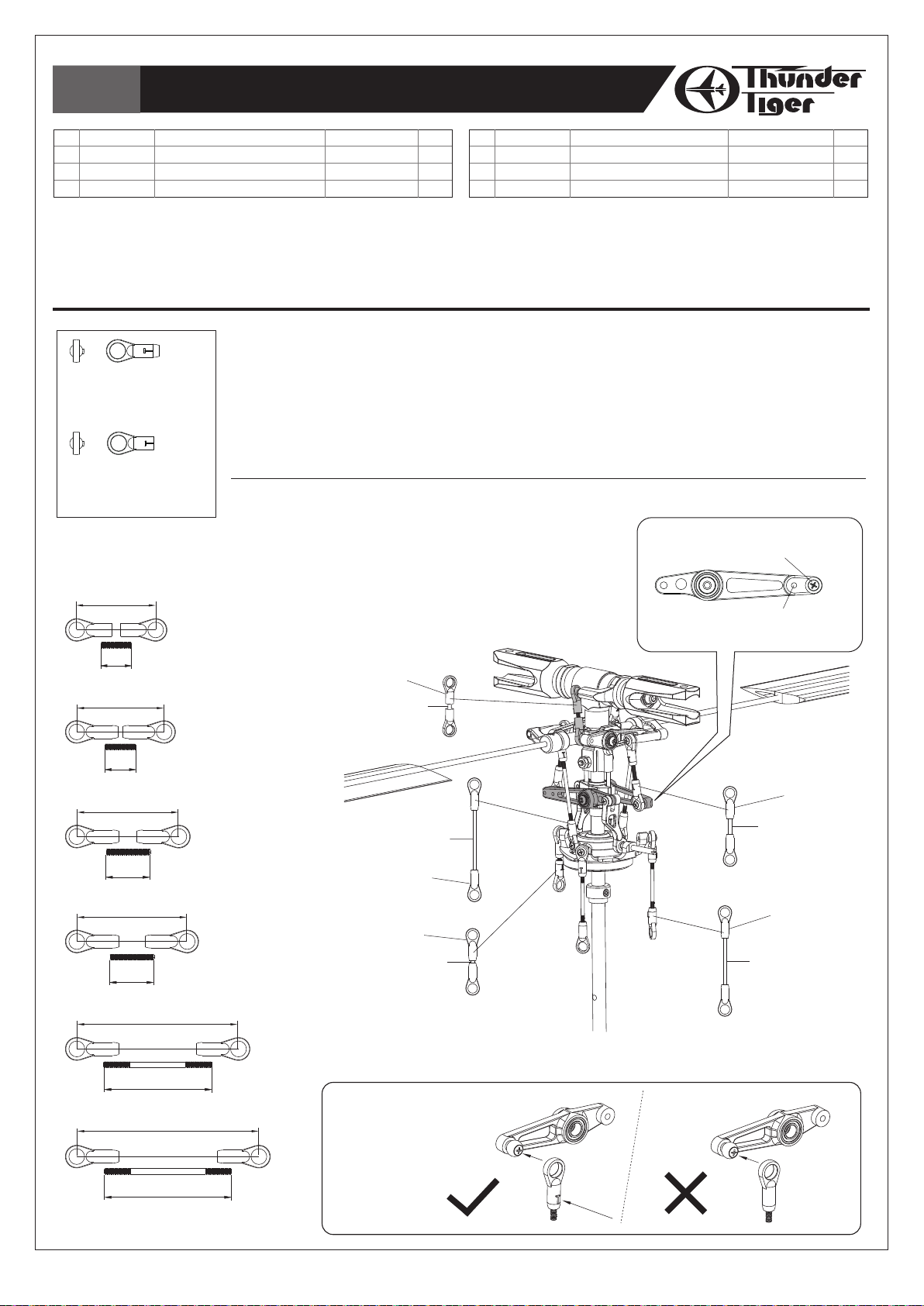
Step 1 / 步驟一
Assemble the Linkage Rods as drawings. The linkage length is measured by the center of the
2 Ball Links. These drawings are printed actual size; you can lay the linkage sets on the left
drawings to measure the correct length.
請參考圖示組裝連桿及連桿頭。連桿長度距離的計算應以兩端連桿頭中心點為基準。圖示尺寸與實物相
同,您可直接對照左方圖示以快速獲得正確長度。
Step 2 / 步驟二
Attach the linkage sets on the main rotor head set.
Please refer below drawing.
參考下圖正確連接連桿組及主旋翼組。
名稱
單頭連接桿
連接桿
單頭連接桿
Qty
4
3
14
No.
Material No.
4
BK1064
5
BK1066
6
BK1065
Description
LINKAGE ROD 1.3X10mm
LINKAGE ROD 1.3x24.5mm
LINKAGE ROD 1.3x29mm
名稱
連接桿
連接桿
連接桿
For 3D flying
3D飛行設定
Qty
2
2
2
18
7
20
7
10
23
25
10
36.5
(A)
X2
(B)
X1
(C)
X2
(C)
X2
For novice
初學者設定
For 3D flying
3D飛行設定
(D)
X2
(1)
(2)
(3)
(3)
(6)
(2)
(A)
(E)
(B)
(C)
(D)
For novice
初學者設定
(3)
(4)
(3)
(5)
24.5
41.5
29
(E)
X2
Note / 注意
T mark on the Ball
Link goes toward
outside.
球頭上T字凸起向外
-12-
Bag E+F
Main Frame Assembly-1 /
本體組裝
-1
No.
Material No.
1
BK1892
2
BV1882
3
BV1883
4
BK1878
5
BK1881
6
HSA2-6
HSA2-6
Button Head Socket Screw, M2x6
半圓頭內六角螺絲
Description
CARBON MAIN FRAME
UPPER BEARING SET
LOWER BEARING SET
FRONT SERVO TRAY
RARE SERVO TRAY
BUTTON HEAD SOCKET SCREW, M2X6
T22
名稱
碳纖側板
上軸承座組
下軸承座組
前伺服機座
後伺服機座
半圓頭內六角螺絲
Qty
2
1
1
2
1
16
No.
Material No.
7
BV2609
8
BV1412
9
BK1445
10
HMY1-5
11
HMD2-6
12
HNX2-10B
Description
TAIL BEARING FLANGE SET
METAL PULLEY SET (14T)
TAIL GEAR 28T
PIN ø1×5.3
FLAT HEAD PHILLIPS SCREW, M2X6
Socket Button Head Self Tapping Screw M2×10
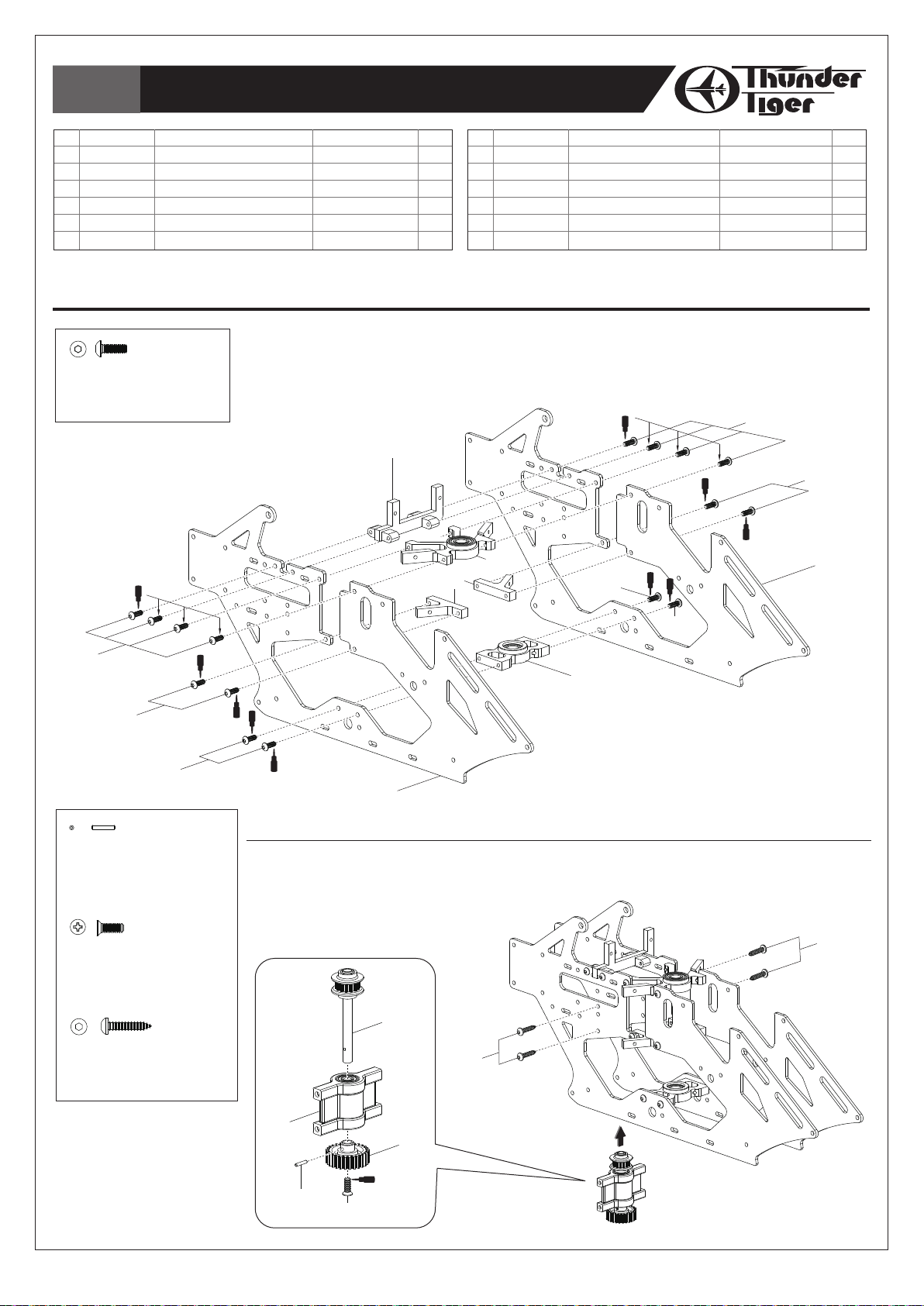
Step 1 / 步驟一
Assemble the left main frame as drawing. Secure the screws with a drop of
threadlocking but not over tighten.
參考圖示組裝左側板。使用適量防鬆劑固定,但請勿過度鎖緊。
T22
(5)
(2)
(4)
(6)
(14T)
28T
M2x6
Qty
1
1
1
1
1
4
名稱
尾傳動齒軸承座組
金屬皮帶輪組
金屬尾驅動齒
插銷
ø1×5.3L
平頭十字螺絲
半圓頭內六角自攻螺絲M2×10
(6)
(6)
(1)
(6)
(6)
(6)
HMY1-5
Pin ø1×5.3
插銷
ø1×5.3L
HMD2-6
Flat Head Phillips Screw, M2x6
平頭十字螺絲
HNX2-10B
Socket Button Head Self Tapping Screw M2×10
半圓頭內六角自攻螺絲M2×10
M2x6
(3)
(1)
Step 2 / 步驟二
1. Assemble the tail drive gear set as drawing.
2. Secure the tail drive gear set to the main frame set.
1. 參考圖示組裝尾傳動齒輪組。
2. 將尾傳動齒輪組組裝至側板組上。
(8)
(12)
(6)
(12)
(7)
(9)
T22
(10)
(11)
-13-

Bag G
Main Frame Assembly-2 /
本體組裝
-2
No.
Material No.
1
BK2601
2
BK2604
3
BK2606
Description
ANTI-ROTATION BRACKET
BATTERY TRAY
BOTTOM BRACKET
Step 1 / 步驟一
1. Assemble the Battery Tray, Anti-rotation Bracket and Bottom Bracket by Tapping
HNX2-6B
Socket Button Head Self Tapping Screw M2×6
半圓頭內六角自攻螺絲M2×6
Screws (M2 x 6, #4) as drawing.
2. Assemble the Canopy Standoff & Standoff Spacer on the main frame set, secure
tightly with a drop of thrardlocking.
1. 參考圖示將電池板、十字盤相位導軌及機身底板以自攻螺絲組裝至側板組。
2. 使用適量防鬆劑將將機殼支柱及定位柱組裝至側板組。
(6)
名稱
十字盤相位導軌
電池板
機身底板
T22
Qty
1
1
1
(5)
No.
Material No.
4
HNX2-6B
5
BK1887
6
BK1888
T22
(6)
Description
Socket Button Head Self Tapping Screw M2×6
STANDOFF SPACER
CANOPY STANDOFF
名稱
半圓頭內六角自攻螺絲M2×6
定位柱
機殼支柱
(1)
(2)
Qty
12
1
2
(4)
(3)
(4)
(4)
-14-

Bag H
Main Frame Assembly-3 /
本體組裝
-3
No.
Material No.
1
BK0933
2
BV0934
3
BK0931
4
BK0930
BK0931
Flat Washer d6×D10×0.3
單向軸套墊
Description
AUTOROTATION TAIL DRIVE GEAR
MAIN GEAR (W/BEARING)
FLAT WASHER D6×D10×0.3
ONE WAY BEARING SHAFT
圈 d6×D10×0.3
名稱
尾驅動輪
主齒輪(含軸承
單向軸套墊
單向軸套
1. The One Way Bearing and the Spacer are pre-assembled.
2. Assemble the Main Gear and the Autorotation Tail Drive Gear with the One Way Bearing
Shaft.
1. 單向軸承與墊片原廠已安裝完成。
2. 以單向軸套組合主齒輪與尾驅動齒輪。
(124T)
圈 d6×D10×0.3
Qty
1
1
)
2
1
(3)
(2)
(4)
Note 2 / 注意 2
1mm
(1)
Note 1 / 注意 1
The Words on the One Way
Bearing is toward bottom
單向軸承刻字端朝下
Spacer
六角軸環
One Way Bearing
單向軸承
Main Gear 150T
主齒輪
-15-

Bag G
Main Frame Assembly-4 /
本體組裝
-4
No.
Material No.
1
BK2602
2
BK2603
3
BK1473
4
HNX2-6B
5
BK1038
HNX2-6B
Button Head Socket Screw, M2x6
半圓頭內六角自攻螺絲M2×6
HME3-3B
Set Screw M3×3
無頭內六角螺絲
HMC2-14B
Socket Screw M2×14
內六角螺絲
Description
ANTENNA HOLDER
CANOPY CLIP
LANDING SKID (BLACK)
Button Head Socket Screw, M2x6
LANDING SKID DAMPER
M3×3
M2×14
(5)
名稱
天線管座
機殼固定夾
(黑)
腳架
半圓頭內六角自攻螺絲M2×6
腳架墊圈
(4)
(4)
(5)
Qty
1
1
1
8
4
No.
Material No.
6
BK1020
7
HME3-3B
8
HMC2-14B
9
HML2
Description
MAIN SHAFT LOCK RING
SET SCREW M3×3
SOCKET SCREW M2×14
M2 NUT
名稱
止擋圈
無頭內六角螺絲
內六角螺絲
M2
M2×14
螺帽
M3×3
Step 1 / 步驟一
Assemble the Landing Skid, Canopy Clip & Antenna
Holder as drawing, and then attach the skid set on the
main frame set.
先組裝腳架、機殼固定夾及天線管座,然後再將腳架組安裝
至側板組。
(3)
(5)
Qty
1
1
1
1
HML2
M2 Nut
M2
螺帽
(1)
(4)
Step 2 / 步驟二
1. Slide the main gear set into the main frame set.
2. Insert the Main Shaft into the Upper Bearing Housing, main
gear set & Lower Bearing Housing.
3. Line up the holes of the Autorotation Tail Drive Gear, One Way
Bearing Shaft & Main Shaft, and then insert the Socket Screw
to fix them with a M2 Nut. Add a drop of threadlocking when
securing, but do not over tighten.
4. Attach the Main Shaft Lock Ring on the end of the Main Shaft.
Secure the ring by a Set Screw with a drop of threadlocking,
note there should be no play of the Main Shaft.
1. 將主齒輪組套入側板組中。
2. 將主軸穿過上軸承座、主齒輪組及下軸承座。
3. 對正尾驅動主齒、單向承軸及主軸上孔位後,穿入內六角螺絲並加上
螺帽,並使用適量防鬆劑固定。注意! 請勿過度緊迫螺絲!
4. 將止擋環套入主軸尾端,使用適量防鬆膠鎖上,正確安裝時,主軸不
會有上下移動之空間。
(2)
(5)
(8)
(9)
Screw Driver
螺絲起子
T22
T22
T22
(7)
(6)
-16-

Bag I
Tail Unit Assembly-1 /
尾管組裝
-1
No.
Material No.
1
BK1073
2
BK1004-1
3
BK1872
4
BV1873
5
BV1874
HMD2-5B
Flat Head Phillips Screw, M2x5
平頭十字螺絲
HSA2-6
Button Head Socket Screw, M2x6
半圓頭內六角螺絲
Description
BELT MXL-3T(413T)
TAIL BOOM 356MMXø14
METAL TAIL UNIT
METAL TAIL SIDE COVER- R
METAL TAIL SIDE COVER- L
M2x5
M2x6
名稱
皮帶
MXL-3t(413T)
尾管
356mmxø14
金屬尾座
金屬尾座側蓋組
金屬尾座側蓋組
Qty
-
右
-
左
No.
Material No.
1
1
1
1
1
6
BK1875
7
BV0973A
8
HMD2-5B
9
HSA2-6
Description
TAIL UNIT SPACER
MATEL TAIL ROTOR SHAFT SET
FLAT HEAD PHILLIPS SCREW, M2X5
BUTTON HEAD SOCKET SCREW, M2X6
Step 1 / 步驟一
Insert the Belt into the Tail Boom. First tape the belt & insert
the end of the belt as shown, and not twist the belt.
將皮帶穿過尾管。用膠帶將皮帶尾端貼合可使皮帶較容易穿過尾管;
並請勿扭轉皮帶。
Note / 注意
(2)
The slot is toward upper side.
尾管上缺口朝上
(1)
Tape / 膠帶
名稱
尾座支柱
尾旋翼軸組
平頭十字螺絲
半圓頭內六角螺絲
M2x5
M2x6
(3)
Qty
1
1
6
1
Step 2 / 步驟二
1. Attach the Metal Tail Side Cover- R to Metal Tail Unit
as drawing.
2. Slide the Metal Tail Unit onto the Tail Boom.
1. 參考圖示將金屬尾座側蓋(右)安裝至金屬尾座上。
2. 將金屬尾座套入尾管。
Step 3 / 步驟三
1. Assemble the Tail Unit as drawing, as well as warp the belt around the Tail Pulley.
2. Secure the Tail Unit to the Tail Boom tightly with a drop of Locitite.
1. 依圖示完成尾部組裝,同時將皮帶繞過皮帶輪。
2. 使用適量防鬆膠將尾部鎖緊在尾管上。
(8)
T22
90°
Note / 注意
The slot o n the boom is
right angle to the Metal
Tail Rotor Shaft. (View
from nose to tail)
請注意,尾管上缺口應與尾
旋翼軸呈直角狀態。
(由機首向機尾
方向看)
T22
(9)
The slot should be at upper side
缺口朝上
(6)
(7)
(5)
(4)
T22
T22
(8)
T22
(8)
-17-

Bag J
Tail Unit Assembly-2 /
尾管組裝
-2
No.
Material No.
1
BK0990
2
BK0991
3
BK1203
4
HSP16-6N
5
HMV520ZZY
BK1203
LINKAGE BALL(ø3.8)
連接頭
(ø3.8)
HSP16-6N
COUNTERSUNK SCREW M1.6×6
圓頭十字螺絲
BK1481
FLAT WASHER d2xD3.7x0.5t
墊片
d2xD3.7x0.5t
Description
TAIL PITH CONTROL LEVER-1
TAIL PITH CONTROL LEVER-2
LINKAGE BALL(ø3.8)
COUNTERSUNK SCREW M1.6×6
BALL BEARING, d2xD5xW2.5
M1.6×6
名稱
尾旋翼控制桿
尾旋翼控制桿
連接頭
(ø3.8)
圓頭十字螺絲
滾珠軸承
d2xD5xW2.5
M1.6×6
Qty
-1
-2
No.
Material No.
1
1
1
1
2
6
HNN2-10B
7
BV1421A
8
BK1091
9
HMC2-16B
Description
TAPPING SCREW(WASHER)
M. TAIL PITH CONTROL SET
DOUBLE JOINT LEVER
SOCKET SCREW M2×16
名稱
墊圈自攻螺絲
金屬尾旋翼攻角控制組
雙關連接桿
內六角螺絲
Step 1 / 步驟一
1. Secure the Double Joint Lever to Tail Unit as drawing.
2. Do not over tighten the Socket Screw, ensure the lever rotate effortlessly.
1. 將雙關節連接桿安裝至尾管座。
2. 固定螺絲請勿過度鎖緊,確認機構能靈活作動。
(9)
T22
Note the orientation of the
triangle mark on the Double
Joint Lever.
請注意雙關連接桿上三角形凸
標的方向。
M2×10
M2×16
Qty
1
1
1
2
HMF2-6N
Countersunk Screw M2×6
圓頭十字螺絲
HMC2-16B
Socket Screw M2×16
內六角螺絲
M2×6
M2×16
Step 2 / 步驟二
1. Secure the Linkage Ball to the Tail Pitch Control Lever-1.
2. Assemble the Tail Pitch Control Lever and the Tail Pitch
Control Set as drawing.
1. 將球頭固定於金屬尾旋翼控制臂上。
2. 如圖示,組裝金屬尾旋翼控制臂組。
(6)
(5)
(2)
(7)
(8)
Step 3 / 步驟三
Do not over tighten the Socket Screw,
ensure the lever runs effortlessly.
請勿過度鎖緊固定螺絲,確認機構作動順暢。
(9)
T22
(1)
(3)
(4)
-18-

Bag K
Tail Unit Assembly-3 /
尾管組裝
-3
No.
Material No.
1
BV1411
2
BK1000
3
HNU2-9Z
4
BK0972
HNU2-9Z
SHOULDERED SCREW M2×9
圓頭十字軸套螺絲
HMV520ZZWY
BEARING D2×D5×2.5
滾珠軸承
BK1080
SAFTY WASHER
墊圈
Description
METAL TAIL PITCH HOUSING
TAIL PITCH LINK
SHOULDERED SCREW M2×9
TAIL ROTOR HUB
M2×9
d2×D5×2.5
M2×9
Qty
2
2
4
1
No.
Material No.
5
HMV520ZZWY
6
BK1080
7
HMC2-8B
8
BK0961
Description
BEARING D2×D5×2.5
SAFTY WASHER
SOCKET SCREW M2×8
TAIL ROTOR BLADE
名稱
滾珠軸承
墊圈
內六角螺絲
尾旋翼
d2×D5×2.5
M2×8
Qty
2
2
2
2
名稱
金屬尾旋翼轉座組
尾旋翼連接頭
圓頭十字軸套螺絲
尾旋翼固定座
Step 1 / 步驟一
1. Secure the Metal Tail Pitch Control Link to the Metal Tail Pitch Housing but do not over
tighten. Note the orientation of the Chamfer on the link.
2. Attach the Metal Tail Pitch Housing into the Tail Rotor Hub by the Socket Screws with a
drop of threadlocking. Note the orientation of the Safety Washer.
1. 如圖示,組裝金屬尾舵控制臂、夾片組,需注意連接座安裝方向性,請勿過度鎖緊固定螺絲,確認
機構可以靈活作動。
2. 組合金屬尾舵控制臂與金屬夾片組,需使用防鬆膠,並注意墊片的安裝方向。
Note / 注意
The orientation of the Satefy Washer
注意墊片安裝方向
HMC2-8B
SOCKET SCREW M2×8
內六角螺絲
M2×8
(8)
(3)
Note
注意
T22
chamfer
倒角
(4)
chamfer
倒角
(8)
(3)
T22
(1) (5) (6) (7)
(2)
(1)
(5)
(6)
T22
(7)
Step 2 / 步驟二
1. Attach the Tail Rotor Blades to the Metal Tail Pitch Housing as drawing. Ensure the leading edges of the blades are
toward proper side as shown.
2. Secure with a drop of threadlocking but do not over tighten the screws.
1. 參考圖示將尾旋翼安裝於金屬尾旋翼夾座。請確認旋翼前橼朝向正確方向(如圖示)。
2. 使用適量防鬆劑固定螺絲,但請勿過度鎖緊。
-19-

Bag L
Tail Unit Assembly-4 /
尾管組裝
-4
No.
Material No.
1
HME3-3B
2
HNU2-9Z
HME3-3B
SET SCREW M3×3
無頭內六角螺絲
HNU2-9Z
SHOULDERED SCREW M2×9
圓頭十字軸套螺絲
Description
SET SCREW M3×3
SHOULDERED SCREW M2×9
M3×3
M2×9
(2)
T22
No.
名稱
無頭內六角螺絲
圓頭十字軸套螺絲
M3×3
M2×9
Qty
1
2
Material No.
3
BK1501
4
HSA2-6
5
HMM2Z
Step 1 / 步驟一
1. Slide the tail rotor set into the Tail Rotor Shaft.
Line the hole up with the concave on the shaft.
2. Secure the tail rotor set tightly by the Set
Screw with a drop of threadlocking.
1. 將組裝完成的尾舵控制臂與夾片組安裝至尾橫軸。
2. 無頭內六角螺絲需準確安裝於尾橫軸固定孔位,並
使用防鬆膠。
Note / 注意
Line up the concave of tail rotor
shaft and the hole of hub.
尾橫軸上凹槽對正轉座上螺絲孔。
Description
3D CARBON TAIL FIN
BUTTON HEAD SOCKET SCREW, M2X6
LUCK NUT, M2
T22
名稱
3D
碳纖維垂直安定面
半圓頭內六角螺絲
止鬆螺帽
(1)
Qty
1
2
2
T22
HSA2-6
BUTTON HEAD SOCKET SCREW, M2X6
半圓頭內六角螺絲
HMM2Z
LUCK NUT, M2
止鬆螺帽
(5)
(2)
Step 3 / 步驟三
Attach the Carbon Tail Fin to the Tail Unit as shown.
將碳纖垂直安定翼固定於尾管座。
Step 2 / 步驟二
Fit the Tail Pitch Control Links to the Tail Pitch Control
Set. Do not over tighten the Socket Screw and ensure
the tail linkages run effortlessly.
將控制連桿與控制臂連接,請使用適量螺絲防鬆劑,勿過度鎖
緊固定螺絲,並確認機構可以靈活作動。
Completed View
組裝完成
(4)
-20-
(3)
Bag M
Tail Boom Bracket Set-1 /
尾管固定座組裝
-1
No.
Material No.
1
BK1082
2
HMJ12-6B
3
BK0923
HMJ12-6B
TAPPING SCREW M1.2×6
圓頭十字自攻螺絲
HNN2-10B
TAPPING SCREW(W/WASHER) M2×10
圓頭墊圈自攻螺絲
Description
ROD GUIDE
TAPPING SCREW M1.2×6
TAIL SERVO TRAY
M1.2×6
M2×10
名稱
固定環
圓頭十字自攻螺絲
尾伺服機座
M1.2×6
Qty
2
2
2
No.
Material No.
4
HNN2-10B
5
BK2610
6
BK1886
Description
TAPPING SCREW(W/WASHER) M2×10
TAIL BOOM BRACKET
BRACKET SPACER
名稱
圓頭墊圈自攻螺絲
尾管固定座
固定座支柱
M2×10
Qty
2
1
2
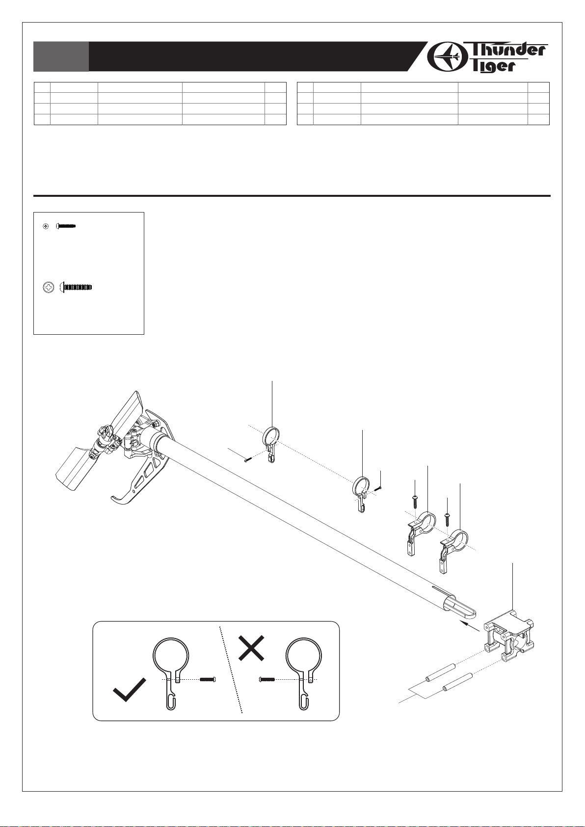
1. Slide the Rod Guides and the Tail Servo Tray onto the Tail Boom.
2. Secure the Self-tapping Screws but do not tighten at this step, the position of these guides
& servo tray may be adjusted later.
3. Insert the Bracket Spacers into the Tail Boom Bracket.
1. 將固定環與尾伺服機座跨入尾管。
2. 使用自攻螺絲稍事固定,以便後續調整。
3. 將固定座支柱穿入尾管固定座中。
Note / 注意
(2)
(1)
(1)
(2)
(4)
(3)
(3)
(4)
(5)
-21-
(6)

Bag M
Tail Boom Bracket Set-2 /
尾管固定座組裝
-2
No.
Material No.
1
HNX2-10B
2
HSA2-6
HNX2-10B
SOCKET BUTTON HEAD SELF TAPPING SCREW, M2×10
半圓頭內六角自攻螺絲 M2×10
HSA2-6
BUTTON HEAD SOCKET SCREW, M2X6
半圓頭內六角螺絲
Description
SOCKET BUTTON HEAD SELF TAPPING SCREW, M2×10
BUTTON HEAD SOCKET SCREW, M2X6
M2X6
M2X6
Qty
4
4
名稱
半圓頭內六角自攻螺絲 M2×10
半圓頭內六角螺絲
Step 1 / 步驟一
1. Remove the tap from the end of the belt. Insert the tail unit into the main frame set,
twist the belt toward right for 90° and then warp around the pulley.
2. First tighten the 4 upper Tapping Screws(HNN2-10B,#1)to attach the Tail Bracket on
the main frame set.
1. 移除皮帶末端膠帶。將尾部套入主側板組中,同時將皮帶向右扭轉90度後,繞過皮帶輪。
2. 先緊鎖上方的兩側4顆螺絲,將尾管固定座固定在主側板組上。
Tail / 機尾
Tail pulley
皮帶輪
90°
Drive Gear Set
尾驅動輪組
Note / 注意
Ensure the leading edge of the blades
rotate this way as drawing. (Turn the Main
Gear clockwise, the main rotor grips turns
clockwise and the Tail Blades turn counter
clockwise.)
請注意旋翼轉動方向應與圖示相同。
(順時針方向撥動主齒盤時,主旋翼頭夾座順
時針、尾旋翼逆時針轉動。)
Step 2 / 步驟二
1. Pull the Tail Boom out
slightly by grasping the Tail
Unit with one hand and the
main frame set with the
other. Adjust until the belt
deflects by about 0.2mm
(0.08”).
2. Tighten the 4 lower Tapping
Screws(HSA2-6B,#2)to fix
the Tail Bracket on the main
frame set.
1. 一手固定主側板組,另一手握住
尾部將尾管向外拉,使皮帶拉緊
。適當的皮帶緊度應於推壓皮帶
時陷下少於0.2mm(0.08”)。
2. 將下方的兩側4 顆螺絲螺緊,將
尾管固定座固定於主側板組。
Nose / 機頭
(1)
(1)
(2)
(2)
-22-
Bag N
Electric System-1 /
電子系統
-1
No.
Material No.
1
BK1890
2
HSA3-5B
3
HME3-3B
HSA3-5B
SOCKET SCREW M3×5
半圓頭內六角螺絲
HME3-3B
SET SCREW M3×3
無頭內六角螺絲
HSA2-6
BUTTON HEAD SOCKET SCREW M2X6
半圓頭內六角螺絲
Description
MOTOR MOUNT
SOCKET SCREW M3×5
SET SCREW M3×3
M3×5
M3×3
M2x6
名稱
馬達座
半圓頭內六角螺絲
無頭內六角螺絲
M3×5
M3×3
Qty
No.
Material No.
1
2
1
4
5
BK1009
HSA2-6
Description
DRIVE GEAR 13T
BUTTON HEAD SOCKET SCREW M2X6
名稱
驅動齒輪
半圓頭內六角螺絲
13T
M2x6
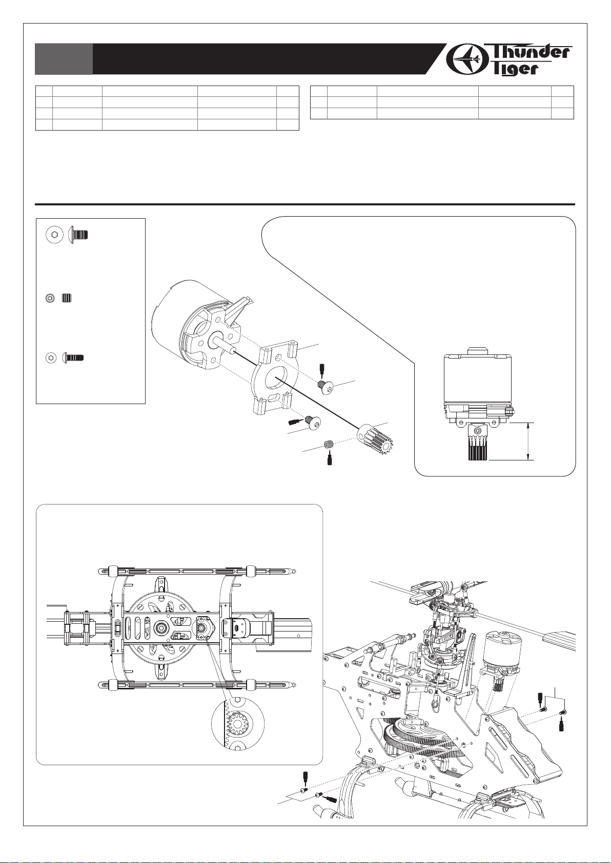
Note 1 / 注意 1
1.
The length from the end of Drive Gear to Motor Mount is 16mm.
2. Please select the Drive Gear based on your motor & battery.
The OBL 29/37-10H (No. 2382) Brushless Motor and 13T
pinion are recommended for mini Titan V2 with ACE
Power 3S1P Li-Po battery.
1. 驅動齒輪末端至馬達座距離為16mm。
2. 請依馬達及電池種類搭配驅動齒輪。使用ACE
RC OBL 29/37-10H無刷馬達,建議搭配
13T驅動齒輪及3S1P鋰聚電池組。
(1)
T22
(2)
Qty
1
4
Step 1 / 步驟一
1. Mount the motor to the Motor Mount.
2. Secure the Drive Gear to the motor shaft tightly
with a drop of threadlocking.
1. 將馬達固定於馬達固定片上。
2. 使用適量防鬆劑將驅動齒論固定於馬達主軸上。
Note 2 / 注意 2
You can observe the gear mesh from the bottom
of Bottom Bracket.
您可從機體底部檢視齒輪間隙。
T22
(2)
(3)
(4)
16mm
T22
Step 2 / 步驟二
1. Install the Motor Mount into the main frame.
2.
Adjust the mesh between the Main Gear and Drive Gear
until there is a small amount of backlash all the way.
1. 將組裝好的馬達座固定於機身。
2. 調整好齒輪間隙之後,確實固定馬達座。
(5)
T22
(5)
T22
T22
-23-
Bag O
Electric System-2 /
電子系統
-2
No.
Material No.
1
HMC2-8B
HMC2-8B
Socket Screw M2×8
內六角螺絲
Description
SOCKET SCREW M2×8
M2×8
名稱
內六角螺絲
M2×8
Qty
6
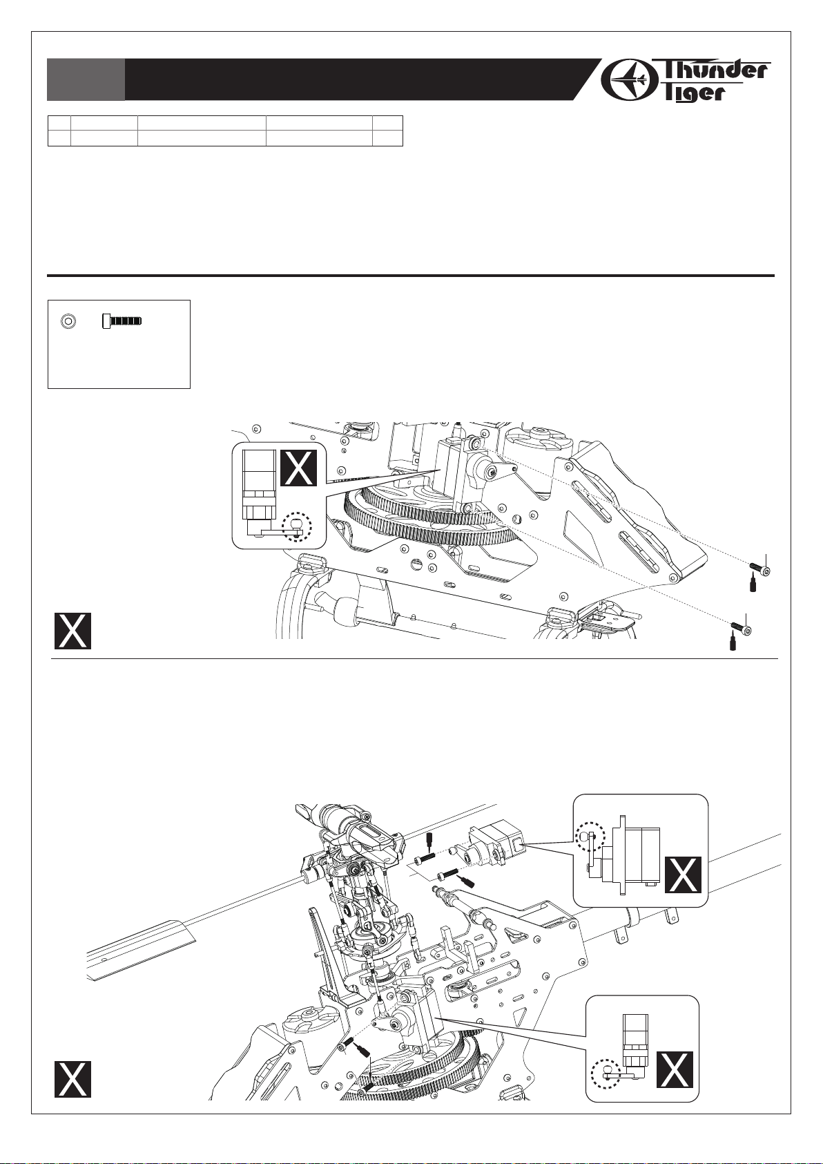
Step 1 / 步驟一
1. Remove the servo wheel prior to attaching the Linkage Ball.
2. Mount the Linkage Ball at 12.5mm from the center of the servo arm.
3. Secure the servo to the right Servo Tray and attach the rod to the servo arm.
1. 從伺服機上將伺服機擺臂拆下,安裝連桿頭。
2. 將連桿頭安裝於距離擺臂中心位置12.5mm處。
3. 將完成連桿頭安裝伺服機安裝於伺服機固定座右側,並與連桿連接。(左右側伺服機擺臂連桿頭朝內)
Must be purchased separately
改裝品需另購
Step 2 / 步驟二
1. Remove all the servo wheels prior to attaching the Linkage Balls.
2. Mount the Linkage Balls at 12.5mm from the center of the servo arms.
3. Secure the servos to the left and to the back, attach the rods to the servo arms.
1. 從伺服機上將另外兩組伺服機擺臂拆下,安裝連桿頭。
2. 將連桿頭安裝於距離擺臂中心位置12.5mm處。
3. 將完成連桿頭安裝伺服機安裝於伺服機固定座左側與後側,並與連桿連接。(後側伺服機擺臂連桿頭朝外)
T22
(1)
(1)
T22
(1)
T22
Must be
purchased separately
改裝品需另購
T22
(1)
-24-

Bag O
Electric System-3 /
電子系統
-3
No.
Material No.
1
BK1026
2
BK1027
3
BK1025
4
BK1889
5
HMC2-10B
6
HMC2-14B
HMC2-10B
SOCKET SCREW M2×10
內六角螺絲
HMC2-14B
SOCKET SCREW M2×14
內六角螺絲
HML2
M2 NUT
M2
螺帽
Description
BRACKET
ROD ø3×255mm
TAIL SUPPORT ROD END
FRAME SPACER
SOCKET SCREW M2×10
SOCKET SCREW M2×14
M2×10
M2×14
名稱
尾支撐桿座
碳纖棒
ø3×255mm
尾支撐桿接頭
機身支柱
內六角螺絲
內六角螺絲
M2×10
M2×14
Qty
1
2
4
1
2
1
No.
Material No.
7
HML2
8
BK1071
9
BK0922
10
HSP16-6N
11
BK1203
12
HNN2-10B
Description
M2 NUT
TAIL LINKAGE ROD ø1.3
BALL LINK D3.8x12mm
COUNTERSUNK SCREW M1.6×6
LINKAGE BALL (ø3.8)
TAPPING SCREW(W/WASHER) M2×10
Step 1 / 步驟一
1. Apply CA or Epoxy when assembling the Tail Support Rod End.
2. Install the Tail Support Bracket and fit the Tail Support Rod.
1. 使用快乾膠接合尾支撐桿接頭與碳纖棒。
2. 將支撐桿座與支撐桿接合。
T22
(3)
(5)
名稱
M2
尾拉桿
單頭連接桿
圓頭十字螺絲
連接頭
圓頭墊圈自攻螺絲
(2)
螺帽
ø1.3
D3.8x12mm
(ø3.8)
M1.6×6
M2×10
T22
Qty
1
1
2
1
1
2
(6)
BK0922
BALL LINK D3.8x12mm
單頭連接桿
HSP16-6N
COUNTERSUNK SCREW M1.6×6
圓頭十字螺絲
BK1203
LINKAGE BALL (ø3.8)
連接頭
HNN2-10B
TAPPING SCREW(W/WASHER) M2×10
圓頭墊圈自攻螺絲 M2×10
D3.8x12mm
M1.6×6
(ø3.8)
(4)
T22
(3)
(5)
CA or Epoxy
瞬間膠或環氧樹脂
CA
(2)
(7)
(3)
Step 2 / 步驟二
1. Remove the tail servo wheel prior to attaching the Linkage Ball.
2. For the rudder servo, mount the Linkage Ball at 10.5mm from
the center of the servo arm as beginning. Please refer to the
manual of your gyro to choose the length of the arm.
3. Secure the servo to the Tail Servo Tray and attach the
rod to the servo arm.
1. 從尾舵伺服機上將伺服機擺臂拆下,安裝連桿頭。
2. 將連桿頭安裝於距離擺臂中心位置10.5mm處作為初始設定,
建議您參考陀螺儀說明書安裝。
3. 將伺服機安裝於尾舵伺服機固定座,並與連桿連接。
(12)
(3)
(1)
(9)
(12)
(11)
(8)
(9)
(10)
-25-

Bag O
Electric System-4 /
電子系統
-4
No.
Material No.
1
BK2605
2
HNX2-6B
3
BD1826-B1
4
BK1088
HNX2-6B
SOCKET BUTTON HEAD SELF TAPPING SCREW, M2×6
半圓頭內六角自攻螺絲 M2×6
Description
RECEIVER TRAY
SOCKET BUTTON HEAD SELF TAPPING SCREW, M2×6
ANTENNA TUBE
RUBBER TUBE 10mm
名稱
接收機座
半圓頭內六角自攻螺絲 M2×6
天線管(黑色)
10mm
軟管
1. Attach the receiver, gyro to the Main Frame by two-sided rubber.
2. Insert the Antenna Tube and fix it by the Rubber Tube.
1. 使用雙面膠固定接收機、陀螺儀於機體。
2. 安裝天線管並使用軟管固定。
Qty
1
4
1
2
(2)
(4)
Gyro / 陀螺儀
Two-Sided Rubber / 雙面膠
(2)
(1)
Two-Sided Rubber / 雙面膠
Receiver / 接收機
(4)
(3)
Note / 注意
Secure the receiver with straps to prevent it from being ejected.
接收機請用適當束帶固定,以防止飛行中鬆脫。
-26-
Must be purchased separately
改裝品需另購

Bag P
Electric System-5 / 電子系統-5
No.
Material No.
1
BK1884
Description
VELCRO STRAPE
(1)
名稱
新式魔鬼粘束帶
Qty
2
No.
Material No.
2
BV2607-Y
3
BK1002
Description
CANOPY
RUBBER GROMMET
名稱
機身
機身固定墊圈
Qty
1. Mount the ESC(Option) either between the frames or under the Battery Tray wherever it fits
and better cooling.
2. Secure the ESC & Battery(Option) with Velcro Straps to prevent them from being ejected.
1. 速控器(選購)可置放於主側板組內,或電池板下方,以速控器尺寸及散熱效果為主。
2. 使用適當固定束帶固定速控器及電池組(選購),以防止飛行中脫落。
Li-po Battery(Option)
鋰聚合物電池(選購)
1
2
BK1884
VELCRO STRAPE
新式魔鬼粘束帶
Must be purchased separately
改裝品需另購
For normal
一般飛行
Canopy Assembly / 機艙罩組裝
Install the Rubber Grommet onto the Canopy as drawing.
將避震墊圈安裝至機身(如圖示)。
1. Wedge the Canopy in the Canopy Clip.
2. Attach the Canopy by pushing the grommets at the
rear of the Canopy onto the Canopy Standoff on
the main frames.
1. 將機身嵌入機殼固定夾。
2. 稍加按壓固定墊圈將機身固定於機身支柱上。
For 3D flying / 3D飛行
(3)
(3)
(2)
-27-

Bag KP1
Main Rotor Blade Assembly /
主旋翼組裝
No.
Material No.
1
BK1442
2
HMC3-20B
3
HMM3Z
HMC3-20B
SOCKET SCREW M3×20
內六角螺絲
HMM3Z
M3 NYLON NUT
防鬆螺帽
M3
Description
BLADE SPACER
SOCKET SCREW M3×20
M3 NYLON NUT
M3×20
名稱
主旋翼墊片
內六角螺絲
M3
防鬆螺帽
M3×20
Qty
2
2
2
For Fiber-glass(FRP) or Carbon Blades:
1. Remember to attach the Blade Spacer on the grips as drawing.
2. Install the main blades with the Socket Screw (HMC3-20B, #3). Do not over tighten and
ensure the blades run effortlessly.
使用玻纖或碳纖維主旋翼時:
1. 請記得加上主旋翼墊片。
2. 以內六角螺絲安裝上主旋翼。請勿過度鎖緊。
(2)
(1)
(3)
For Wood Blades:
For safety concern, ensure the wood blades are assembled as per the following:
1. Mark around the blade grips with a felt tip marker.
2.
Remove the blade grips and cut the covering gently around 1mm inside of the mark. Be careful not to damage the blades.
3. Sand the inside of the grips lightly for better adhesion. Apply CA or Epoxy to blades in area as shown.
4. Attach blade grips and tighten the screws.
5. Wipe off the excess CA or Epoxy.
6. Calibrate and balance the weight before using.
Remove the membrane along the grips.
移除該部份包膜
木槳主旋翼組裝:
安全起見,請確實依下列程序組裝主旋翼木槳:
1. 將主旋翼連接座與旋翼進行假安裝,並於旋翼包
膜上描繪連接座形狀。
2. 移開連接座,以刀片依連接座形狀小心地切除包
膜,請注意勿切割到旋翼本體。
3. 可將連接座內側稍以砂紙打磨,以增加黏著力。
將去除包膜的旋翼部份平均塗上快乾膠,如下圖
所示。
4. 將旋翼連接座合入旋翼本體,並確實鎖好螺絲。
5. 去除多餘滲出的膠水,即完成。
6. 進行配重及平衡。
Note / 注意
1. You may need to adjust the linkage to ensure the blade tracking. Please refer page 39 “Blade Traking
Adjustment”.
2. For safety, we strongly suggest using wood or FRP blades for level flight only, rpm should not exceed 1500.
Upgrading to carbon blades for F3C or 3D flying is strongly recommended.
3. For safety the rpm of using carbon blades should not exceed 3200.
1. 您可能必需調整相關的連桿來確保旋翼旋轉軌跡正常。請參閱第39頁“主旋翼軌跡調整”說明。
2. 安全起見,在飛行F3C科目或3D動作時,我們強烈建議您將主旋翼換裝碳纖維槳;木槳或玻纖槳僅適合旋翼轉速不超過
1500rpm的一般飛行使用。
3. 安全起見,碳纖維主旋翼轉速請勿超過3200rpm。
CA Glue or Epoxy
快乾或環氧樹脂
CA Glue or Epoxy
快乾或環氧樹脂
-28-

INTRODUCTION OF E-CCPM CONTROL SYSTEM / E-CCPM 控制系統介紹
The E-CCPM(Electric Cyclic/Collective Pitch Mixing) system offers the users a control system that can
accomplish the same control as traditional M-CCPM(Mechanical Cyclic/Collective Pitch Mixing) system, but
with simple machinery. The 120°E-CCPM system utilizes 3 servos for the main control of aileron, elevator
and collective pitch. The 3 servos work independently from each other of M-CCPM system, but they work
as a team to achieve the same control of the E-CCPM system. For example, if a collective input is given, all
of the 3 servos work together to move the swashplate up and down. If an aileron input is given, 2 servos
work at the same time to make the swashplate inclined. With servos working together during any given
command, the torque is maximized. In addition, E-CCPM system execute the given control inputs with less
complex mechanical mixing systems and require less control rods and parts.
In today’s modern computer radio system, the E-CCPM system is established in the program. Since the
120°E-CCPM function are pre-programmed, there is no more complicated mixing/setup than the M-CCPM
system. For the radio type and brand, please choose which has the 120°E-CCPM function. Please note
that it is not possible to use a non-E-CCPM radio system for E-CCPM operation without any other electronic
mixer.
電子式E-CCPM控制系統,操作介面與傳統機械式M-CCPM系統控制原理相似,但相較於傳統式整個結構卻更為簡化。
120°E-CCPM系統使用三顆伺服機,分別控制副翼、升降舵與螺距混控。在傳統混控模組裡,這三顆伺服機均獨立作
業;在E-CCPM系統中,這三顆伺服機互相連動,可視為一個完整的組合。假設目前有一個混控指令,三顆伺服機將
一起作動完成十字盤上提或下推;假設一個副翼控制指令下達,另外兩顆伺服機將同時作動,推動十字盤。 所有的控
制指令均同時由三顆伺服機一起作動,可發揮最大驅動扭力,確實完成動作。E-CCPM系統執行動作時,整體複雜性
遠低於傳統CCPM,更達到簡化零配件與維修便利的目的。
市面上電腦化遙控器系統,均內建E-CCPM模組。透過內建的120°模組,可簡易的完成設定。建議您選購內建
120°E-CCPM遙控器,才可進行120°E-CCPM模組設定。
MOVEMENT OF 120°E-CCPM SYSTEM / E-CCPM 120°說明
The given inputs are executed by the team work of the 3 servos through the mixing program of the radio or
the electronic mixer. The following are the examples showing how the movement be carried out.
COLLECTIVE PITCH
When a collective pitch command is given, all of the 3 servos move toward the same direction with same
speed and same travel distance. This movement is to raise or lower the swashplate and keep the
swashplate level. Thus, the required collective pitch can be reached without cyclic input.
透過遙控器內建E-CCPM模組或外接式電子混控器發出指令,由三顆伺服機同部
完成動作。下列說明E-CCPM作動原理:
螺距混控
螺距混控模式下,三顆伺服機同步作動,伺服機方向、速度、行程均一致。
將十字盤永遠保持在水平的狀態下運作。
-29-
(Right View /
右側圖)

MOVEMENT OF 120°E-CCPM SYSTEM / E-CCPM 120°說明
AILERON
Aileron is controlled by the 2 servos in the front. When an aileron command is given, one servo will pull the
swashplate downward and the other will push the swashplate upward so that the roll command is executed.
They move contrary with same speed and travel distance, and the third servo in the back remains still at this
moment.
副翼
副翼由前方兩顆伺服機控制。副翼執行動作時,一顆伺服機上推十字盤、另一顆下拉十字盤,完成動作,此時另一顆
伺服機保持中立點。
(Rear View /
ELEVATOR
The elevator is controlled by all of the 3 servos. When an elevator command is given, the 2 servos in the front
move in the same direction and the third one move contrary. For example, when a down elevator command
is given, the 2 front servos pull the swashplate downward and the third one push the swashplate upward so
that the down elevator command is executed. The 3 servos pull/push the swashplate at the same time to
accomplish the given command.
升降舵
升降舵由三顆伺服機同步控制,執行升降舵指令時,前方兩顆伺服機,將會配合第三顆伺服機進行連動。因此三顆伺
服機在推、拉十字盤時將會以相同的速度與行程量同時進行完成動作。例如執行降舵時,前方兩顆伺服機拉下十字
盤,第三顆上推十字盤完成動作。
後視圖)
(Right View /
右側圖)
(Right View /
-30-
右側圖)
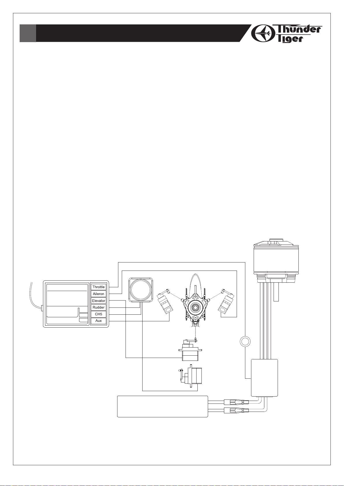
SERVO CONNECTING / 伺服機連結
E-CCPM system requires 3 channel for aileron, elevator and an AUX(for pitch). But people may get
confused because the 3 channels are not referred to any independent movement. They are operated
together to carry out the rolling, flipping and collective controlling. As a result, the following connecting
manner is recommended.
1. The rear servo located in back of the swashplate MUST be plugged into the elevator channel.
2. Suppose the servo in the right side is plugged into the aileron channel.
3. The left servo is plugged into the AUX channel.
The following chart is the E-CCPM connecting for your reference. Please also consult your radio
instruction manual.
E-CCPM系統需要使用三個通路予副翼、升降舵、與螺距(使用AUX通道)。許多愛好者可能會對於此設定感到困
惑,但是在混控模式下,必須藉由三顆伺服機同時完成動作,因此建議依照下列說明完成伺服機與接收機連結。
1. 十字盤後方伺服機與接收機ELEVATOR通道連接。
2. 右側伺服機與接收機AILERON通道連接。
3. 左側伺服機與接收機AUX通道連接。
下列圖示為安裝範例,實際接線方式,請參照您的遙控器使用說明書。
Gyro / 陀螺儀
Left Servo
左側伺服機
Receiver / 接收機
Brushless Motor
無刷馬達
Left Servo
右側伺服機
Magnet Ring
防磁環
Elevator Servo
升降舵伺服機
Li-Po Battery
鋰聚電池組
-31-
Rudder Servo
尾舵伺服機
Speed
Controller
速控器
BASIC CONCEPT OF ADJUSTMENT / 基礎設定與調整
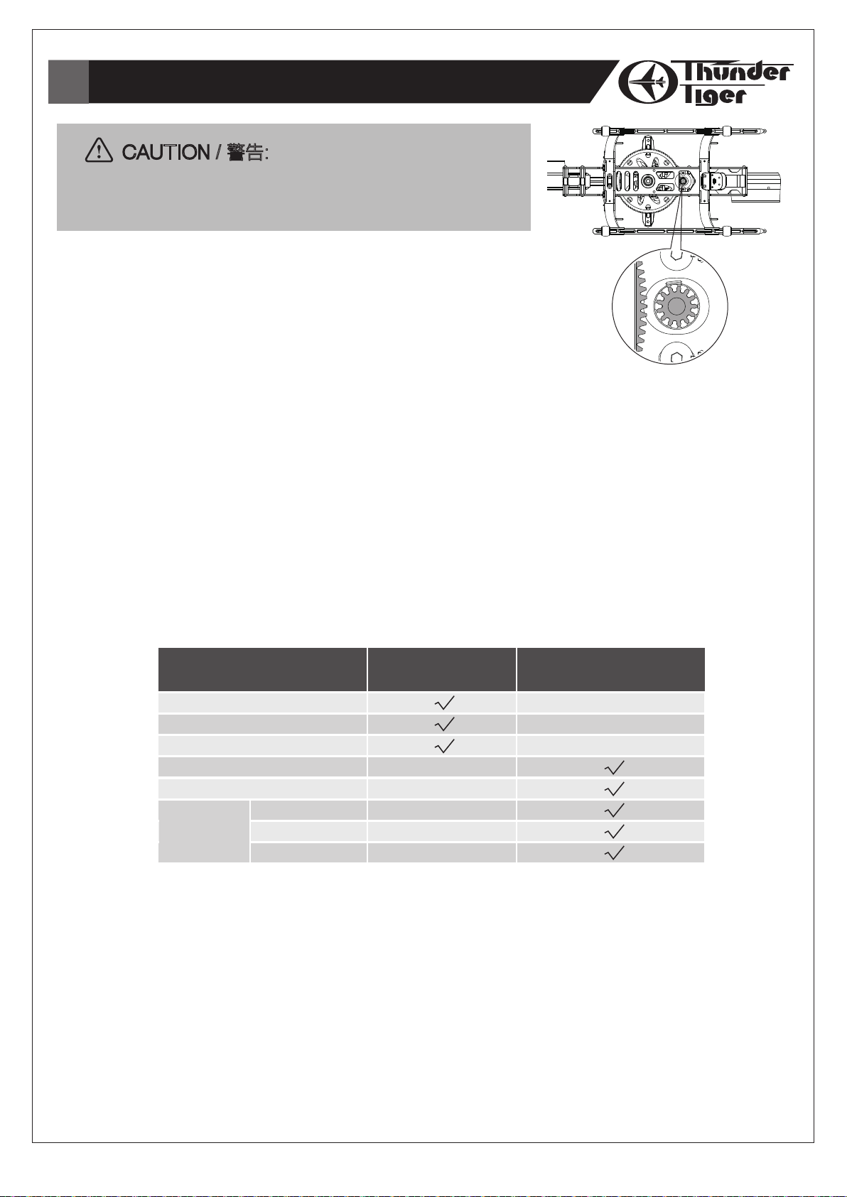
CAUTION / 警告:
For satety, ensure to perform this procedure with the
motor pinion away from the main gear.
執行此步驟時,請將馬達驅動齒與主齒盤脫離。
Because people may be confused with the operating manner of the E-CCPM
system, we want to explain the basic concept of how to center and trim the
servo while adjusting the full travel distance.
First of all, we have to make it clear about what do you want to adjust. Do
you want to adjust the servo itself or the control surface? For example, if
you want to adjust the servo which is plugged into the aileron channel itself,
only the servo will be adjusted. But if you want to adjust the aileron "rolling"
surface, the two servos plugged into aileron and AUX channels will be adjusted. Making clear of this basic
concept will simplify the process of adjustment.
Furthermore, you have to realize the function of “Reverse”, “Sub Trim”, “Trim”, “Travel
Adjustment”, “D/R & EXP” and “Swash Mixing” of the transmitter. There are different names for
those functions between different brands of the radio, but their definitions are basically the same. The
following table shows the functions which those items refer to:
針對E-CCPM模組下,各伺服機的中立點、行程等設定概念作一簡單說明。首先,須先確認要調整的項目為伺服機本
身或是整個控制介面。假如您要調整副翼控制通路,您只會調整到副翼控制伺服機;假設您要調整整個副翼控制介
面,就必須要調整副翼與螺距控制伺服機。確認完欲調整項目之後,調整的過程將會更加順手。進一步,必須了解發
射機上(REVERSE / 正逆轉)、(SUB TRIM / 微調)、(TRIM)、(D/R&EXP大 / 小動及指數值)、
(TRAVEL ADJUSTMENT / 行程量調整)的涵義。市售遙控器因品牌與功能差異,相同的功能卻有不同的名稱,但
是基本的意義都是一致的。適用範圍請參照下列表格:
Items
項目
Reverse / 正逆轉
Sub Trim / 微調
Travel Adjustment / 行程量調整
Trim / 微調
D/R & EXP / 大小動及指數值
Swash Mixing
十字盤混控
± Aileron / 副翼
Elevator / 升降舵
±
± Pitch / 螺距
Adjust the Servo Itself
調整伺服機
Adjust the Control Movement
調整控制介面
Therefore, if you want to adjust servos themselves, please use the “Reverse”. “Sub Trim”, and
“Travel Adjustment”. If you want to adjust the control surface, please use the “Trim”, “D/R & EXP”
and “Swash Mixing”.
For example, it is necessary to do minor centering adjustments to achieve the desired servo arm position
with the “Sub Trim” function. Under this circumstance, you have to adjust the servo itself, not the control
surface.
如欲調整伺服機,必須使用到REVERSE(正逆轉)、SUB TRIM(微調)、TRAVEL ADJUSTMENT(行程量調整
功能);如欲調整控制介面將會使用到TRIM(微調)、D/R&EXP(大小動及指數值)、SWASH MIXING(十字盤
混控調整功能)。
例如,如欲調整伺服機中立點位置,需用到SUB TRIM(微調)功能,而不是其他調整控制介面的功能。
-32-
BASIC CONCEPT OF ADJUSTMENT / 基礎設定與調整
Before starting, make sure the following preparation is done.
1. Set all trims, knobs, and switches to the neutral and zero position.
2. Reset the radio to its factory preset position.
3. Choose the 120°E-CCPM swashplate control mode.
Reversing/Swash Mixing
The moving direction of servos has to be confirmed. You can attach the servo arms to the servos
temporarily so that it makes it easier to see the servos moving direction. While giving a positive collective
pitch, all of the 3 servos are supposed to be moving in the same direction to descend the swashplate. If the
3 servos are moving in the same direction but to raise the swashplate, you have to use the “swash
mixing” function to make it descend. If any of the servos is moving contrary, you have to adjust the one by
“reverse” function. Since the moving manner above is determined, the “reverse” function of
Aile/Elev/AUX is done.
Next, you have to check the control surface. While giving a cyclic pitch control, the swashplate has to be
tilted toward the correct direction. If not, you have to adjust it by “swash mixing” function. For example, if
a down elevator command is given, the swashplate is supposed to be tilted forward. If the swashplate is
tilted rearward, you have to change the +/- of the elevator control surface by “swash mixing” function. So
as the aileron control surface.
To sum up, the “reverse” function is to adjust the servo itself, and the +/- of the “swash mixing”
function is to adjust the control surface.
Servo Arms
After the moving direction of the servos is determined, please center the collective control stick. With the
collective control stick is centered, install the servo arms of the 3 servos. They are supposed to be level. If
the servo arms tilt with a small degree, use the “sub trim” function to adjust it independently. Thus the
procedure of centering is complete.
開始設定之前,請先確認下列注意事項
1. 發射機上所有的調整旋鈕、機構均位於中立點。
2. 重新設定原廠內建數據。
3. 選擇E-CCPM 120°模式。
正逆轉/十字盤混控設定
開啟電源確認伺服機運作方向是否正確,您可以觀察伺服機擺臂作動方向來判斷。發射機送出正螺距指令,三顆混控
伺服機運作方向應一致,來下拉十字盤。假設伺服機運作方向一致,但是卻推舉十字盤,此時必須使用十字盤混控設
定功能來調整。若是有單獨伺服機運作方向相反,此時應調整單一伺服機正逆轉方向。上述調整工作完成後,即完成
十字盤混控設定。
接下來,確認控制介面設定。利用發射機指令來確認十字盤混控系統是否正確運作,如不正確,請調整十字盤混控設
定。假設執行升降舵向下指令時,十字盤應該向前傾斜,如果呈現向後傾斜,必須在十字盤混控設定功能裡,修改設
定升降舵+/-。副翼調整方式同上。
正逆轉功能(reverse)為單獨調整伺服機用,調整介面需使用十字盤混控設定。
伺服機擺臂
伺服機運作方向正確無誤後,請將所有撥桿調回中立點位置,將伺服機擺臂與連桿相互垂直地安裝至伺服機上。如果
有些微差距,可利用副微調裝置完成設定。
-33-
BASIC CONCEPT OF ADJUSTMENT / 基礎設定與調整
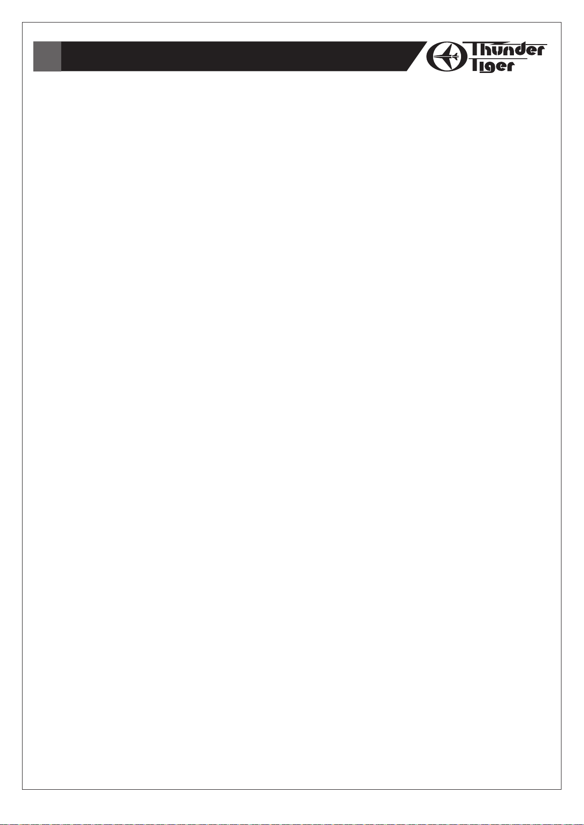
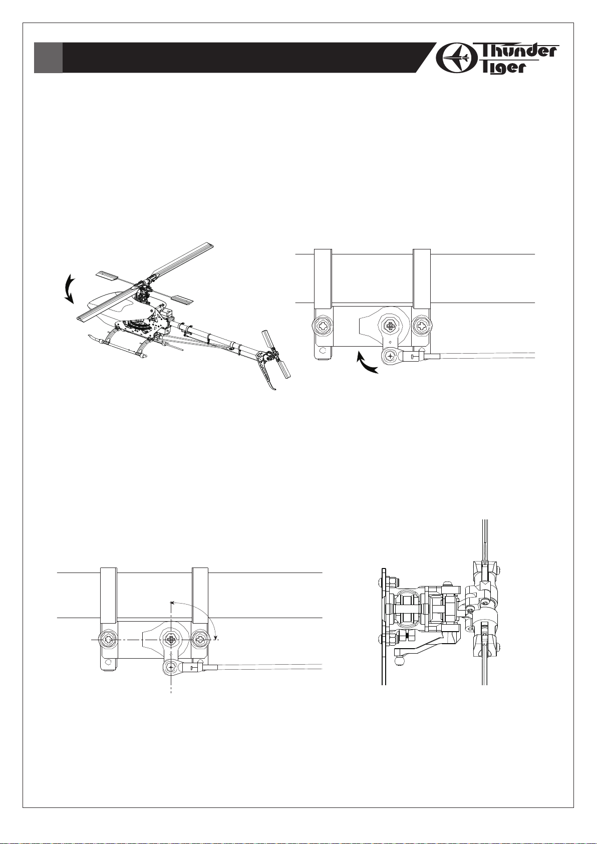
Level the Swashplate
After centering the servos, setting the length of the control linkages and attaching them to the link balls, it
is important to check the swashplate that it is level. Turn on the transmitter and the receiver, do not
connect to the Motor at this moment, and center the collective pitch stick. Make sure all the trims and
knobs are centered and the pitch curve should be 0% at low end and 100% at high end at present. The
servo arms should be level. While the collective pitch stick is centered and the servo arms are level, the
swashplate is supposed to be level. First, check the swashplate from the rear of the model to insure if it’s
level from left to right. If the swashplate is not level as compared to the frame of the model, adjust either
the left or right servo control rods. Next, check the swashplate from a side of the model to insure if it’s
level from head to rear. If the swashplate is not level, adjust the control rod of the servo in the back.
調整十字盤水平度
將所有連桿與球頭連接,在伺服機保持中
立點位置下,確認十字盤水平度。將接收
機與發射機電源打開(勿與速控器相連
接),確認所有撥桿位於中立點位置,以
及(pitch curve)最低點為0﹪最高為
100﹪。伺服機擺臂應該為垂直狀態。所
有的伺服機以及擺臂處於垂直狀態下,十
字盤必須位於水平位置。首先,從機體尾
部朝基頭方向,觀察十字盤是否左、右呈
現水平(如後視圖);再從機體側面觀察
十字盤是否左、右呈現水平(如右視
圖)。若十字盤未呈現水平狀態,必須將
左、右連桿一起調整。
Level
水平
Level
水平
(Rear View /
(Right View /
後視圖)
右側圖)
It always happens that the travel of each servo varies slightly. If so, the swashplate would be tilted when
giving a full collective pitch command. These variations can be corrected by altering the travel value of each
servo slightly by using the “Travel Adjustment” function.
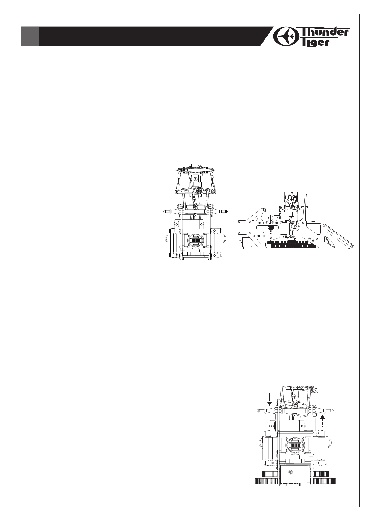
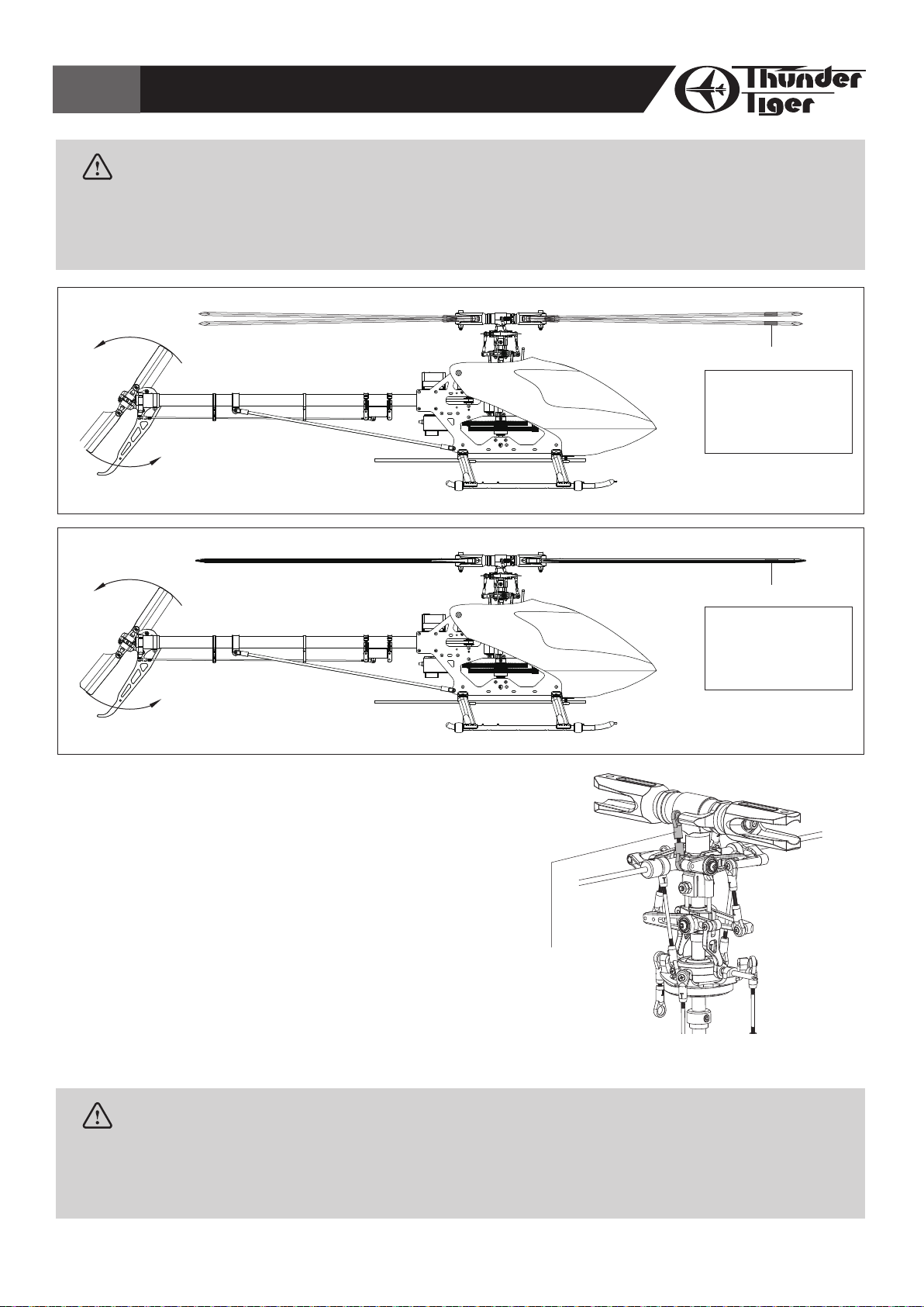
Pitch to Aileron Mixing
Place the collective stick to the full positive pitch position. Check the swashplate from the rear of the model
to insure if it’s level from left to right. If the swashplate is not level as compared to the frame of the model,
adjust either the servos by using the “Travel Adjustment” function.
For example, the swashplate has been tilted to the right side while giving full positive collective pitch. It
indicates that the left servo’s travel is less than the right servo’s travel. You can either increase the travel
of left servo or decrease the travel of right servo. Check the swashplate
again to insure that it’s level.
It is necessary to repeat the procedure while giving full negative
collective pitch. Check if the swashplate is level and adjust the servos as
needed while the full negative collective pitch is given.
混控模組下,十字盤會隨著連桿的推拉產生傾斜,每一顆伺服機的行程量,可
以在遙控器的行程設定功能(Travel Adjustment)改變設定。
副翼與螺距混控修正
將發射機螺距撥桿置於最高側,從從機體尾部朝基頭方向,觀察十字盤是否
左 、 右 呈 現 水 平 。 若 未 呈 現 水 平 狀 態 , 請使 用行 程設 定功 能( Tr av el
Adjustment)調整。假設十字盤向右傾斜(如圖示),表示左側伺服機行程量
小於右側伺服機,您可選擇增加左邊伺服機行程量或減少右側伺服機行程量,
將十字盤調整至水平狀態,將螺距撥桿置於最低側,重複以上步驟以確保十字
盤水平。十字盤確認工作相當重要,必須反覆確認至完全呈現水平狀態為止。
Increase
增加
(Rear View /
Decrease
減少
後視圖)
-34-

BASIC CONCEPT OF ADJUSTMENT / 基礎設定與調整
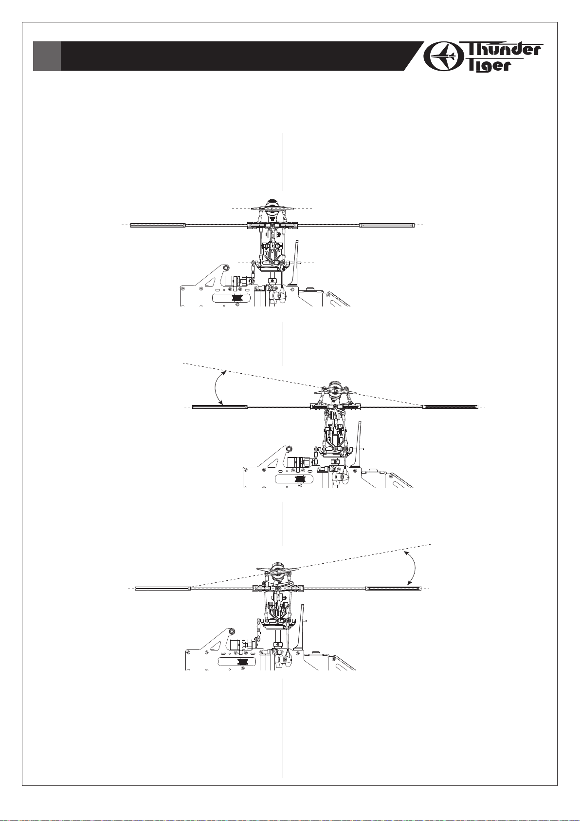
Pitch to Elevator Mixing
Through the previous step, we’ve got rid of
the pitch to aileron mixing. It is as important
to vanish the pitch to elevator mixing. Place
the collective stick to the full positive pitch
position. Check the swashplate from a side
of the model to insure if it’s level from head
to rear. If the swashplate is not level, adjust
the elevator servo by using the “Travel
Adjustment” function.
For example, the swashplate has been tilted
forward while giving full positive collective
pitch. It indicates that the elevator servo’s
travel is less than the rest two’s travel.
Please increase the travel of elevator servo.
Check the swashplate again to insure that
it’s level.
It is necessary to repeat the procedure while
giving full negative collective pitch. Check if
the swashplate is level and adjust the elevator servo as needed while the full negative collective pitch is given.
Increase
增加
(Right View /
右側圖)
升降舵與螺距混控修正
完成上一步驟後,接下來校正升降舵螺距。將發射機螺距撥桿置於最高側,從機體側面觀察十字盤是否前、後呈現水平
(如下圖)。若十字盤未呈現水平狀態,須使用行程設定功能(Travel Adjustment)調整升降舵控制伺服機。假設十
字盤向前傾斜(如圖示),表示升降舵伺服機行程量小於另外兩顆伺服機,需增加升降舵伺服機行程量,使十字盤達到
水平。將螺距撥桿置於最低側,重複以上步驟以確保十字盤水平。
SETTING UP OF LINKAGE / 連桿設定
The lengths of the linkage rods are recommended as the following:
連桿設定建議長度,請參照下列圖示
The length is measured by
the center of the 2 ball links.
以兩端球頭中心點距離長度為連
18mm
25mm
41.5mm
20mm
桿長度
36.5mm
The pushrod length above is suitable for beginner and 3D flying. You can use those lengths as the starting
setting, and adjust the lengths for your flying style. The lengths of the pushrods are measured from the
center of the linkage ball to the center of another.
圖示連桿長度適用於初學者與3D進階飛行。您可在初步設定時依照圖示數據,後續再依照自己的飛行風格改變設定。
連桿長度以兩端球頭中心點距離長度為標準。
-35-
SETTING UP MAIN ROTOR COLLECTIVE PITCH ANGLE / 主旋翼螺距設定
Since you have been setting the lengths of the pushrod as mentioned, the linkage should be centered well as
described below.
若您依照前述設定連桿長度,連桿位置將如下述。
Centering
1. The levers should be as the drawing below while
centering the collective pitch stick.
2. Parallel the flybar, the main blades should be at 0
degree and the swashplate should be level.
Maximizing
1. Place the collective stick at high end.
2. The main blades should be at 10 degree and
the swashplate should be level.
-10°
中立點
1. 發射機撥桿置於中立點時,升降舵與副翼面應呈現水平狀
態(如圖示)
2. 平衡片與主旋翼應呈現平行狀態(0°),十字盤呈現水
平。
0°
最大設定角度
1. 將螺距撥桿上推至最高點。
2. 主旋翼相對於平衡桿角度為10°,十字盤呈現水平。
Minimizing
1. Place the collective stick at low end.
2. The main blades should be at 10 degree and the
swashplate should be level.
NOTE:
1. The steps above define the limits of the collective
pitch setting.
2. The setting of the maximum collective pitch
depends on your personal flying skill and style.
Too much collective pitch could overload the ESC,
motor and the battery. And it will reduce the flying
time also.
最小設定角度
1. 將混控撥桿下推至最低點。
2. 主旋翼相對於平衡桿角度為-10°,十字盤呈現水平。
-10°
注意事項
1. 上述步驟為主旋翼螺距設定範圍。
2. 最大設定角度依照您個人的飛行技巧與習慣而定,過大
的角度將容易導致速控器、馬達與電池發生過載現象,亦
會縮短飛行時間。
-36-

SETTING UP DATA FOR YOUR REFERENCE / 設定參考值
The following is the setting up data of pitch curve and throttle curve for your reference only. Please ask
experienced pilot to help you if you have never done this before.
下列螺距與油門設定數值,僅提供您參考用。如果您是一位新手,建議您可求助於專業雷虎科技經銷商或有經驗的同
好以完成設定。
Throttle Curve Pitch Curve
Novice / 初學者
Throttle Curve / 油門曲線
1
2
Thro. Pitch
100
75
100
75
Normal
0
453654855100
Pitch Curve / 螺距曲線
1
2
3
Normal
40
-
75
Pitch Angle / 攻角
1
2
Normal
-2°
-3+5°4-5+10°
Aerobatic Flying / 特技飛行
Throttle Curve / 油門曲線
1
2
3
0
45
Normal
Idle 1
Idle 2
80
100
65
-
70
-
80
85
50
25
7550250
100 Stick
100 Stick
4
5
-
100
Throttle Curve Pitch Curve
Thro.
100
75
4
5
100
-
100
-
100
100
50
25
Thro.
50
25
◎ Normal◎ Normal
100
100
75
50
25
Pitch
Pitch
Stick7550250
1007550250
Stick1007550250
Pitch Curve / 螺距曲線
1
Normal
Idle 1
Idle 2
Hold
30
20
5
0
Pitch Angle / 攻角
1
Normal
Idle 1
Idle 2
Hold
-4°
-6°
-9°
-10°
75
2
3
4
5
-
75
-
75
-
-
2
-
+5°
-
+5°
-
-
-
100
-
95
-
-
95
-
-
100
3
4
5
-
+10°
-
+9°
-
-
+9°
-
-
+10°
50
25
Thro.
100
75
50
25
◎ Idle-up 2
7550250
7550250
100 Stick
100 Stick
75
50
25
◎ Idle-up 1◎ Idle-up 1
Pitch
100
75
50
25
◎ Idle-up 2
100
75
50
25
◎ Hold
Stick1007550250
Stick1007550250
Stick1007550250
-37-
TAIL CONTROL AND GYRO SETUP / 設定參考值
It is recommended to use a Heading Hold Gyro. With a Heading Hold Gyro, you may not use the trim and the
revolution mixing function of tail control.
First, choose the length of the tail servo arm referring to the manual of the Gyro. You may try 10.5mm as
the starting setting. Then mount the servo arm for the moment and check the movement of the tail servo:
1. While giving the right rudder control, the servo arm should move forward.
2. Rotate the helicopter with your hand counterclockwise, the servo arm should move forward.
建議使用鎖定式陀螺儀來作為尾舵控制系統,可為您帶來使用與設定上的便利與可靠度。
首先,參考陀螺儀使用手冊來設定尾舵伺服機擺臂長度。建議您可以10.5mm作為初步設定長度。將擺臂固定於伺服機
上,並與尾舵拉桿連接。
1. 尾舵控制桿右舵指令,伺服機擺臂向前擺動。
2. 手持機體逆時針轉動,尾舵伺服機擺臂向前擺動。
Rudder Servo
尾舵伺服機
After esuring of moving direction of tail servo, you have to mount the servo arm in the correct position.
Please reset the receiver power and do not move the helicopter. While the tail control stick and trim are
centered, mount the servo arm vertically. Next, two points may be your concern:
1. The traveling limit of the tail servo may not go beyond the mechanical movement.
2. The tail servo horn should be vertical while the tail rotor are at 0 pitch or with a little offset to the
right.(Referring to the drawing below)
確認尾舵伺服機作動方向後,即可將伺服機擺臂安裝於伺服機上。安裝時,記得重新開啟接收機電源且勿移動直昇機。
伺服機擺臂須以90°安裝(如圖示)。請確認擺臂位於中立點位置及下列兩點注意事項:
1. 尾舵最大行程量,勿超過尾舵機械行程量。
2. 尾舵伺服機擺臂在中立點時,尾舵螺距應為0°或稍偏向右舵(如圖示)。
90°
Rudder Servo
尾舵伺服機
Note
1. To find the traveling limit, you have to adjust the Gyro referring to its manual.
2. To adjust the pirouetting speed of the helicopter, please use the ”Travel Adjustment” or the ”D/R &
EXP” function.
注意事項
1. 您可參考陀螺儀說明書,確認尾舵最大行程量。
2. 調整尾舵自旋轉速,請使用行程設定功能(Travel Adjustment)或是(D/R&EXP)功能調整。
-38-
Blade Tracking Adjustment 主旋翼軌跡調整
CAUTION / 警告
For safety, ensure to keep a safe distance from the helicopter at least 5 meter (15 feet) while making tracking
adjustment.
安全起見,進行主旋翼軌跡調整時,請至少與直昇機保持5米(15呎)的安全距離。
color tape / 色標貼
Out of Track / 雙槳
Adjustment is
necessary.
需要調整
1. Use a color tape at the tip of main blades for tracking
identification easily.
2. Increase the main blade speed to just before the helicopter
lifts-off.
3. Observe which blade appears to be lower than the other,
and increase the pitch of the lower blade one turn of the
Linkage Rod A (refer Page 12) at a time until each blade
runs in track. If both main blades rotate in the same path, it
doesn,t need to be adjusted.
1. 在主旋翼前端貼上色標可方便辨識軌跡。
2. 提高主旋翼轉速使機體稍懸浮於地面。
3. 觀察兩支旋翼軌跡是否有落差(雙槳),調整軌跡較低旋翼上的
連桿A (參閱第12頁) 長度,一次調整一圈,直至兩支旋翼軌跡
一致。若軌跡一致則無需調整。
color tape / 色標貼
In Track / 軌跡正確
Adjustment is
unnecessary.
不需要調整
Linkage Rod A
(refer Page 12)
連桿A (參閱第12頁)
CAUTION / 警告
Out of track causes vibration, instability and a loss of power due to additional drag. Please adjust the tracking
repeatedly until the blades are in track properly.
旋翼軌跡落差(雙槳)會造成直昇機震動、不平衡及損失動力。請務必進行調整以使旋翼軌跡精準正確。
-39-
USING OF LI-PO BATTERY / 鋰聚電池使用注意事項
The mini Titan V2 is an electric RC helicopter. It is strongly recommended to use Lithium Polymer Battery.
Please refer to the following information and precaution:
1. Do use a charger that is designed for Li-Poly batteries only.
2. Do not overcharge the battery over the maximum voltage of 4.2V/per cell.
3. Do not discharge the battery below the minimum voltage of 3.0V/per cell.
4. Do not charge the battery unattended.
5. Do not charge the battery in a flammable circumstance.
6. If you want to store the battery for a long time, store them at 3.8V/per cell.
Please understand the information and precaution above and that you agree to accept the full responsibility
of using the battery and any injury caused by the battery. Thunder Tiger and its duly authorized distributors
assume no liability for damage that could occur by the improper using of the battery.
強烈建議使用鋰聚合物電池,作為 mini Titan V2 迷你電動直升機動力來源。請依照下列事項正確使用鋰聚合物電池
,避免危險發生。
1. 使用鋰聚合物電池專用充電器。
2. 勿過度充電,單一電池最大電壓勿超過4.2V/cell。
3. 勿過度放電,單一電池最低電壓勿低於3.0V/cell。
4. 隨時監測電池充電工作,避免發生危險。
5. 勿暴露於易燃環境中,執行充電事項。
6. 長期儲存電池,請保持單一電池電壓3.8V/cell。
請詳細閱讀並充分了解上述注意事項。並同意對於不當使用電池所造成的意外或傷害,由玩家親負全責。雷虎科技與
授權經銷商對於不當使用電池所造成的意外或傷害,不負任何法律上的責任。
TROUBLE SHOOTING / 問題排除
Helicopters / 直升機本體
Q: What would you check when the helicopter
shakes during flying?
A: a. Are the main blades out of track?
b. Are the paddles out of track?
c. Are the main blades well balanced?
d. Are the paddles well mounted at the same
distance from the
e. rotor shaft?
f. Is the spindle or the flybar bent?
g. Is the main shaft bent?
h. Is the main rotor hub damaged?
i. Is the motor well installed and is the shaft
of the motor bent?
j. Is the tail rotor shaft bent?
k. Is the tail rotor hub damaged?
l. Do all the ball bearings work well?
Q: 空中飛行時,機體發生震動該如何排除問題?
A: a.主旋翼是否發生雙槳?
b.平衡片偏擺?
c.主旋翼平衡是否正確?
d.左、右平衡片是否等距?
e.橫軸、平衡桿是否彎曲變形?
f.主軸是否彎曲變形?
g.主旋翼固定座是否損傷?
h.馬達是否正確安裝?馬達驅動軸是否變形?
i.尾驅動軸是否彎曲變形?
j.尾旋翼固定座是否損傷?
k.全機軸承是否運作正常?
-40-

TROUBLE SHOOTING / 問題排除
Helicopters / 直升機本體
Q: What would you do if there comes out a lot of
noise from the helicopter during flying?
A: a.Please check the gear mesh between the
main gear and the motor pinion. If there is too
much gear mesh, it would generate a lot of
gear noise during flying.
b.If the tail drive belt is too loose, it will bring
about some noise and may cause the failure
of tail control.
c.Check the linkages and control system of
main rotor and tail rotor to make sure every
linkage is working correctly and not colliding
with something else.
d.Check if the motor is running out of balance.
Q: 空中飛行時,機體發生過大噪音該如何排除問題?
A: a. 檢查主齒輪與馬達驅動齒間隙是否過大,過大的間
Motor, Battery and Speed Controller / 馬達、電池與速控器
隙將於飛行時產生噪音。
b. 尾傳動皮帶是否過鬆?過鬆的皮帶會產生噪音與降
低尾舵效率。
c. 檢查主旋翼與尾旋翼所有控制連桿是否正常運作。
d. 檢查馬達動平衡是否正常。
Q: How to choose the motor and the pinion?
A: It depends on the battery and the motor. The
following is the formula of how to calculate the
wanted head speed.
Motor RPM = Motor KV x Volt(3.7V) x Series x
constant (0.8)
Head Speed = Motor RPM / Gear Ratio
Gear Ratio = 150T / Motor Pinion
Example:
We choose TT OBL 29/37-10H optional
brushless motor.
If using a 3S(11.1V) Li-Po battery, the motor rpm
should be
3700KV x 3.7V x 3S x 0.8=32856 rpm
And we expect to have the head speed of
2800~3000 rpm
32856 / Gear Ratio=2900
Gear Ratio=11.33
The pinion would be 150T/11.33=13.24
So we choose 13T as the motor pinion.
Q: 該如何選擇適合的馬達與馬達驅動齒
A: 選擇馬達時應同時注意與速控器的搭配性,您可依
照下列公式計算出主旋翼轉速、馬達轉速與搭配的
齒輪比
馬達轉速=馬達kv值×電壓(3.7v)×串聯電池數
×常數(0.8)
主旋翼固定座轉速=馬達轉數/齒輪比
齒輪比=150T/ 馬達齒
實例一:
使用雷虎科技無刷馬達TT OBL 29/37-10H
搭配3S(11.1V)鋰聚電池
馬達轉速=3700KVX3.7VX3SX0.8=32856rpm
欲將主旋翼轉速控制在2800-3000rpm左右
主旋翼轉速=32856/齒輪比=2900
因此齒輪比需為11.33
150T/11.33=13.24
所以馬達齒使用13T
-41-

Heli Accessories / 選購配件
BALL LINK REAMER ( Ø3.8mm) 球頭絞刀
Step 1 / 步驟一
1. Attach the Ball Link to the Reamer.
2. Make sure that the Ball Link is perpendicular
to the reamer as shown.
1.
將絞刀與連接頭接觸。
2.
確認絞刀壓入時與連接頭平面垂直。
Step 2 / 步驟二
1. Turn the Reamer clockwise to trim the
hole of the Ball Link.
2. Turn the Reamer once at a time and do
over trim the Ball Link.
小心將絞刀以順時針方向旋轉,使連接頭擴孔。
1.
2.
每一次旋轉一圈做確認,以免孔擴太大。
inner
not
Item No. / 料號:1198
T mark on bottom
T 字符號在下方
One Way Bearing Releaser 單向軸承退出器
Item No. / 料號:1080
INTRODUCTION 產品簡介
The one Way Bearing Releaser is designed for E325. You can release
the one way bearing very easily from the main gear so that you can
change the main gear without changing the one way. This saves the
maintenance cost indeed.
專為mini Titan E325設計的單向軸承退出器。使用此特殊的治具,您可以
輕易地分解與安裝mini Titan E325的主齒盤與單向軸承,且不使單向軸承
因組裝不當而損壞。在維修的時候,能夠大幅節省您的花費與時間,是您
不可缺的一項維修利器。
FEATURES 特點
Suitable for mini Titan E325 series helicopter.
Tools for releasing the one way bearing of the main gear as well as for putting it back in.
User friendly and easy operation.
適合mini Titan E325全系列電動直升機
用於分解與安裝主齒盤單向軸承
操作簡單、使用容易
RELEASING 分解
Step 1 / 步驟一
Spacer
Main gear
主齒輪
1mm
六角軸套
One way
bearing
單向軸承
A
B
B>A
The words on the one way bearing is toward bottom.
單向軸承刻字朝下
-42-

Heli Accessories / 選購配件
BLADE BALANCER 主旋翼平衡器
Item No. / 料號:1077
INTRODUCTION 產品簡介
Thunder Tiger Blade Balancer is a multi-function balancer for
your blades. You do the balancing job before putting the blades
onto the heli so that you get rid of the vibration problem. Please
reviewing the manual thoroughly that you grasp the function of
the balancer.
雷虎科技主旋翼平衡器,可以進行主旋翼的動、靜平衡量測與調整。
我們建議您在使用任何的主旋翼之前,都儘可能地進行主旋翼動、靜
平衡調整,以免直昇機實際飛行時發生無可預期的震動。請仔細閱讀
並保存此使用說明書,以徹底瞭解該平衡器的功能與使用方式。
Set up 安裝
Step 1 / 步驟一 Step 3 / 步驟三
Step 2 / 步驟二
Thumb Screw
固定螺母
Balance Wing
平衡翼
Bearing Lock
軸承扣
Base
基座
Seesaw Bridge
蹺蹺板
FEATURES 特點
Multi-function blade balancer.
The Seesaw Bridge can be unloaded and easy to store.
Bridge with ball bearing support for accurate balance.
Bridge with a level for easy adjustment and inspection.
Bridge with weights for calibration.
Suitable for static balancing.
Suitable for dynamic balancing.
多功能主旋翼平衡器
蹺蹺板可以卸下並收藏於基座內
蹺蹺板支承處配有滾珠軸承以達到精準量測要求
附有水準氣泡方便調整與觀測
附有平衡重錘以作為初始率定
可進行動、靜平衡量測
Level Indicator
水準氣泡
Blade Rack
旋翼架
Calibration Weight
平衡重錘
-43-

Heli Accessories / 選購配件
BLADE BALANCER 主旋翼平衡器
USERS GUIDE 使用說明
Dynamic Balance 動平衡
1. Open the Blade Rack.
打開旋翼架
Blade Rack and mark at
the same side
旋翼架與記號線在同側
3. Use the Calibration Weight to reset the bridge and
make sure the bridge is leveled via inspecting the
level.
使用平衡重錘率定平衡器,
並觀察水準氣泡是否位於中間位置。
Item No. / 料號:1077
2. Attach the Seesaw Bridge with the Bearing Lock.
將蹺蹺板以軸承扣固定
4. Place the blade on the rack then you can mark the
C.G. when the bridge is leveled.
將旋翼置於旋翼架上尋找重心,並在重心位置上作記號。
Static Balance 靜平衡
1. Use the Calibration Weight to reset the bridge and
make sure the bridge is leveled via inspecting the level.
使用平衡重錘率定平衡器,並觀察水準氣泡是否位於中間
位置。
3. Pull the blades all the way straight so that you can check
the weight of the blades and do the balancing.
確定兩主旋翼呈一直線以進行靜平衡調整。
NOTE / 注意事項
For blades length above 550mm, please open the Balance Wing.
For 4mm bolt holes, please use the collar included.
For 5mm blot holes, please turn over the Mounting Cap.
量測550mm以上主旋翼,請打開平衡翼。
4mm的主旋翼固定孔,請使用內附的軸套。
5mm的主旋翼固定孔,請將固定螺母倒轉。
2. Put the blades on the Seesaw Bridge and secure them
with the Thumb Screw.
將主旋翼鎖至蹺蹺板上。
Leading edge
翼前緣方向
parallel
平行
FOR 4MM BOLT HOLES
4MM主旋翼固定孔
This side up
凸緣向上
Collar
d3xD4x10W
軸環
Leading edge
翼前緣方向
FOR 5MM BOLT HOLES
5MM主旋翼固定孔
This side down
凸緣向下
-44-

Heli Accessories / 選購配件
B A
BB
AA
BLADE BALANCER 主旋翼平衡器
STORAGE 攜帶與收藏
The Seesaw Bridge can be put inside the base for
easy storage.
蹺蹺板可以卸下並收藏於基座內
RECOMMENDED BALANCING PROCESS 平衡執行流程
The following is the recommended balancing process
to correct the position of the C.G. as well as balancing
the weight of the blades.
請參考以下流程修正主旋翼重心位置,同時針對旋翼重量
進行平衡。
1. Please do the “Static Balance” first and find out
which blade is lighter than the other. The lighter
blade is supposed to be the object to be adjusted.
(Mark A)
請執行靜平衡量測,並選取較輕的旋翼作為調整對象
(做上記號A)。
2. Proceed with the “Dynamic Balance” and check
the C.G. position of both blades. Adjust the C.G.
position of the lighter blade(A) as illustration.
Make sure the C.G. position of the lighter blade is
the same as the heavier one.
針對較輕的旋翼(A)進行重心位置調整,目的在使兩
旋翼的重心位於相同位置。
3. After adjusting the C.G., please do the “Static
Balance” again. It is recommended to use the
sticker on the new C.G. position of the lighter blade.
Please note that the C.G. position won’t be
changed after static balance.
再度進行旋翼的靜平衡重量調整,目的在使兩旋翼的
重量相同。請注意配重貼紙必須貼在新的重心位置上,
避免重心位置再度改變。
NOTE / 注意事項
Please note how to use the sticker to balance
the blade. It may be easily lifted off if you
don’t tape it correctly as illustrated.
請注意配重貼紙的使用方式,若配重貼紙的貼法
錯誤,將很容易在飛行中被撕離旋翼表面。
Item No. / 料號:1077
Heavier Blade (Mark B)
較重的槳做上記號B
B
B A
new C.G
Step 3 / 步驟三
Change C.G to new
postion by sticker
使用配重貼紙將旋翼重心移
至新位置
(與B重心相同位置)
BB
A
or
或者
Move C.G to inner side
貼上配重貼紙於內側,將
重心往右側移
or 或
AA
Lighter Blade (Mark A)
較輕的槳做上記號A
Step 1 / 步驟一
Mark C.G position of
A and B blades
在A跟B旋翼上做重心的記號
Step 2 / 步驟二
Mark new C.G position on A blade
(Same position with B blade)
在A旋翼上標示新重心記號
new C.G
(與B重心相同位置)
Move C.G to outer side
貼上配重貼紙於外側,
將重心往左側移
wind
風向
wind
風向
wind
風向
Sticker on new C.G positioni
配重貼紙必須貼在重心位置
A blade
-45-
Lighter Blade
較輕的槳
new C.G
B blade
or
或
C.G

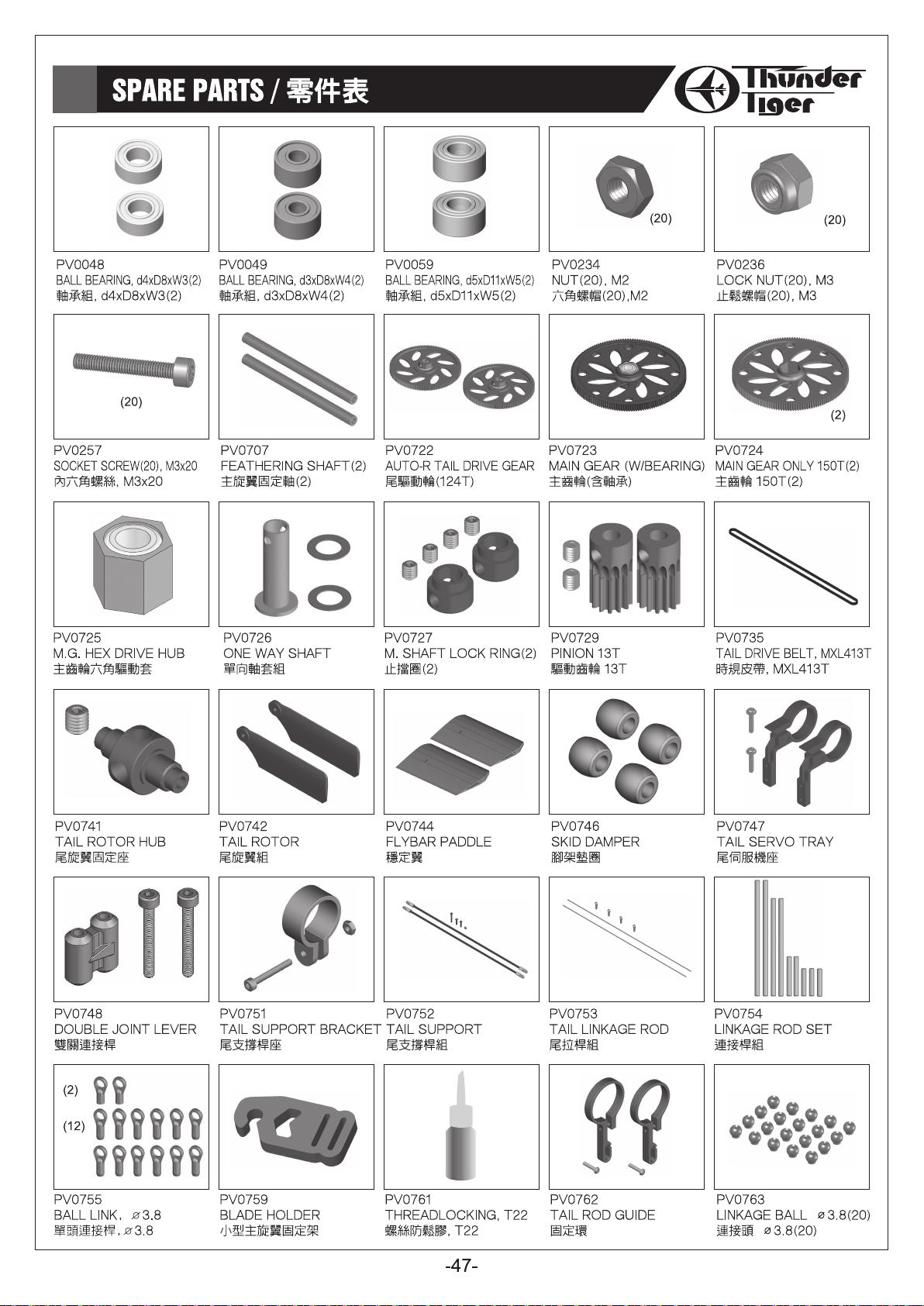

SPARE PARTS / 零件表
(20)
PV0764
COUNTER SCREW, M1.6x6(20)
圓頭十字螺絲, M1.6x6(20)
(10)
(10)
PV0774
SHOULDERED SCREW, M2x9
圓頭十字軸套螺絲, M2x9
PV0781
SCREW BAG
螺絲包
PV0765
CANOPY MOUNT RUBBER
機頭罩固定墊圈
(20)
PV0775
SOCKET SCREW(20), M2x14
內六角螺絲, M2x14
(20) (20)
PV0785
SOCKET SCREW(20), M2x14
半牙內六角螺絲, M2x14
PV0769
THRUST BEARING(2), d4xD9x4
止推軸承組, d4xD9xW4
PV0770
BEARING(10), d2xD5x2.5t
滾珠軸承, d2xD5xW2.5
(20)
PV0776
SOCKET SCREW(20), M2x16
內六角螺絲, M2x16
PV0786
SHOULDERED SCREW(20), M2x6
圓頭軸套螺絲(20), M2X6
PV0777
SOCKET SCREW(20), M2x8
內六角螺絲, M2x8
PV0787
FLAT WASHER(20), d2xD3.7x0.5t
墊片(20), d2xD3.7x0.5t
(20)
(20)
PV0771
BEARING(4), d4xD9x4t
滾珠軸承, d4xD9xW4
(20)
PV0780
SET SCREW(20),M3x3
無頭內六角螺絲, M3x3
(10)
PV0788
COLLAR(10), d2xD3x2.5t
軸環(10), d2xD3x2.5t
PV0789
COLLAR(10), d2xD3x5.6t
軸環(10), d2xD3x5.6t
PV0805
METAL MIXING LEVER
金屬控制搖臂
PV0749
TAIL PITCH CONTROL LEVER SET
尾旋翼控制桿
PV0801
METAL M. ROTOR HUB
金屬旋翼固定座組
PV0807
M. FLYBAR C. LEVER
金屬穩定翼控制臂
PV0820
M. TAIL P. CONTROL SET
金屬尾旋翼控制組
PV0802
HARDENED MAIN SHAFT
高強度主軸
PV0808
METAL WASHOUT BASE
金屬控制臂座
PV0739
TAIL PITCH CONTROL LINK
尾旋翼連接頭
-48-
PV0803
METAL ROTOR GRIP
金屬旋翼轉座
PV0809
METAL SWASHPLATE
金屬十字盤組
PV0823
M. TAIL P. HOUSING
金屬尾旋翼轉座
PV0804
METAL SEESAW HUB
金屬穩定桿固定座
PV0814
METAL PULLEY
金屬尾旋翼軸組
PV0829
ROTOR SPACER
(FOR 5mm BLADE ROOT)
主旋翼墊片

SPARE PARTS / 零件表
PV0837
3D FLYBAR PADDLE
3D穩定翼
PV1267
CARBON MAIN FRAME
碳纖側板
PV1228
REAR SERVO TRAY
後伺服機座
PV0838
M. FLYBAR C. ARM
金屬穩定翼轉臂
PV1224
PHASING CONTROL & BRACKET SET
導軌夾扣零件組
PV1229
LOWER BEARING BLOCK
下軸承座
PV0842
3D CARBON TAIL FIN
3D碳纖維垂直安定面
PV1225
BATTERY & RECEIVER TRAY SET
電裝固定座零件組
PV1230
UPPER BEARING BLOCK
上軸承座
PV0844
SUS FLYBAR ROD
不鏽鋼穩定桿
PV1226
BASE PLATE
機身底板
PV1231
CANOPY POST
機殼支柱
PV0903
LANDING SKID(BLACK)
腳架(黑色)
PV1227
FRONT SERVO TRAY SET
前伺服機座組
PV1232
FRAME SPACER
機身支柱
PV1233
TAIL BEARING FLANGE
尾傳動齒軸承座
PV1237
METAL TAIL UNIT
金屬尾座
PV1244-Y
FRP CANOPY(YELLOW)
玻纖機殼(黃色)
PV1247
METAL PULLEY SET
金屬皮帶輪組
PV1238
METAL TAIL SIDE COVER SET
金屬尾座側蓋組
PV1245
LINKAGE METER & LEVEL TOOL SET
量測工具
PV1234
TAIL BOOM BRACKET
尾管固定座
PV1239
SCREW PACK FOR TAIL UNIT
尾座螺絲組
PV1246
DAMPER(65˚)
避震墊圈(65˚)
(8)
(26)(24)
PV1235
BUTTON HEAD SOCKET SCREW SET
M2半圓頭螺絲組
PV1240
MOTOR MOUNT
馬達座
PV1156
TAIL BOOM,356mm xø14mm
尾管,356mm xø14mm
PV1236
METAL TAIL UNIT SET
金屬尾座組
PV1241
ANTENNA TUBE SET
天線管組
-49-


SPARE PARTS LIST / 維修零件包表格
No. Description Part No.中文名稱 Description Qty
PV0777
PV0780
PV0781
PV0785
PV0786
PV0787
PV0788
PV0789
PV0801
PV0802
PV0803
PV0804
PV0805
PV0807
PV0808
PV0809
PV0814
Socket Screw Set
Set Screw Set
Screw Pack
Socket Screw Set
Shouldered Screw Set
Washer Pack
Collar Pack
Collar Pack
Metal Main Rotor Hub
Hardened Main Shaft Pack
Metal Rotor Grip Set
Metal Seesaw Hub Set
Metal Mixing Lever Set
Metal Flybar Control Lever Set
Metal Washout Base Set
Metal Swashplate
Metal Pulley Set
內六角螺絲組
無頭內六角螺絲組
螺絲包
半牙內六角螺絲組
圓頭軸套螺絲組
墊片包
軸環包
軸環包
金屬旋翼固定座組
高強度主軸包
金屬旋翼轉座組
金屬穩定桿固定座組
金屬控制搖臂組
金屬穩定翼控制臂組
金屬控制臂座組
金屬十字盤
金屬尾旋翼軸組
HMC-8B
HME3-3B
BK0919
BK0920
BK1079
BK1080
HME3-3B
HMJ12-6B
HML2
HMO26
HNN2-10B
HNN2-6B
HNU2-9Z
HNV2-6Z
HSP16-6N
BK1086
HNU2-6Z
BK1481
BK1456
BK1480
BK0918
BK1054
BK1086
BV1408
HML2
BK1086
BK1502
HML2
BK1203
BV1402
HSP16-6N
BK1456
BV1403
HNU2-6Z
BK1203
BK1480
BK1481
BV1404
HNU2-9Z
HSP16-6N
BV1406
BK1203
BK1480
BK1481
HNU2-9Z
HSP16-6N
BV1405
BK1481
BV1419A
BV0973A
Socket Screw, M2x8
Set Screw, M3x3
Washer, d2xD3.8X0.5t
Washer, d2xD3.8X0.2t
Collar, d4xD7
Washer
Set Screw, M3x3
Tapping Screw, M1.2x6
Nut, M2
Washer
Tapping Screw w/Washer
Tapping Screw w/Washer
Shouldered Screw, M2x9
Flat Shouldered Screw, M2x9
Counter Screw, M1.6x6
SOCKET SCREW(S), M2x14
Shouldered Screw, M2x6
Washer, d2xD3.7X0.5t
Collar, d2xD3x2.7t
Collar, d2xD3x5.6t
Washer, d4xD7.8X0.1mm
Damper, 70
Socket Screw, M2x14
Metal Main Rotor Hub Set
Nut, M2
Socket Screw, M2x14
Hardened Main Shaft
Nut, M2
Link Ball,φ3.8
Metal Rotor Grip
Counter Screw, M1.6x6
Collar, d2xD3x2.7t
Metal Seesaw Hub
Shouldered Screw, M2x6
Link Ball,φ3.8
Collar, d2xD3x5.6t
Flat Washer, d2x3.7x0.5t
Metal Mixing Lever
Shouldered Screw, M2x9
Counter Screw, M1.6x6
Metal Flybar Control Lever
Link Ball,φ3.8
Collar, d2xD3x5.6t
Washer, d2xD3.7X0.5t
Shouldered Screw, M2x9
Counter Screw, M1.6x6
Metal Washout Base
Washer, d2xD3.7X0.5t
Metal Swashplate
Metal Tail Rotor Shaft Set
中文名稱
內六角螺絲
無頭內六角螺絲
墊片
墊片
軸環
墊圈
無頭內六角螺絲
自攻螺絲
六角螺帽 M2
墊片
墊圈自攻螺絲
墊圈自攻螺絲
圓頭十字軸套螺絲
扁頭十字軸套螺絲
圓頭十字螺絲
半牙內六角螺絲
圓頭十字軸套螺絲
墊片
軸環
軸環
墊片
避震墊圈
半牙內六角螺絲
金屬主旋翼固定座組
六角螺帽, M2
半牙內六角螺絲
高強度主軸
六角螺帽 M2
連接頭
金屬主旋翼固定座
圓頭十字螺絲
軸環
金屬穩定桿固定座
圓頭十字軸套螺絲
連接頭
軸環
墊片
金屬控制搖臂
圓頭十字軸套螺絲
圓頭十字螺絲
金屬穩定翼控制臂
連接頭
軸環
墊片
圓頭十字軸套螺絲
圓頭十字螺絲
金屬控制臂座
墊片
金屬十字盤
金屬尾旋翼軸組
M2x8
M3x3
d2xD3.8X0.5t
d2xD3.8X0.2t
d4xD7
M3x3
M1.2x6
M2x9
M2x9
M1.6x6
M2x14
M2x6
d2xD3.7X0.5t
d2xD3x2.7t
d2xD3x5.6t
d4xD7.8X0.1mm
70
M2x14
M2x14
M1.6x6
d2xD3x2.7t
M2x6
φ3.8
d2xD3x5.6t
d2x3.7x0.5t
M2x9
M1.6x6
φ3.8
d2xD3x5.6t
d2xD3.7X0.5t
M2x9
M1.6x6
d2xD3.7X0.5t
20
20
20
20
20
10
10
6
2
1
1
2
2
4
2
2
2
2
1
2
4
2
2
2
2
4
2
2
2
2
2
2
1
4
1
1
Index Page
20, 28
8,11,16,20,23
*
4
*
4
*
2
*
2
8,11,16,20,23
3
21
4
10,16,25
4
9
2
21,25
5
*
5
7,11,19,20
2
6
2
7,8,9,11,18,25
5
10
6
7, 11, 19
6
7
*
*
10
1
6
10
10
10
10
9
9
9
6
6
6
11
11
11
11
11
11
11
11
11
11
11
11
11
11
11
17
-51-

SPARE PARTS LIST / 維修零件包表格
No. Description Part No.中文名稱 Description Qty
PV0749
PV0820
PV0739
PV0823
PV0829
PV0837
PV0838
PV0842
PV0844
PV0903
PV1267
PV1224
PV1225
PV1226
PV1227
PV1228
PV1229
PV1230
PV1231
PV1232
PV1233
PV1234
Tail Pitch Control Lever Set
Metal Tail Pitch Control Set
Tail Pitch Control Link
Metal Tail Pitch Housing Set
Rotor Spacer
3D Flyabare Paddle Set
Metal Flyabar Control Arm Set
3D Carbon Tail Fin Set
SUS Flyabar Rod
Landing Skid Set
Carbon Main Frame
Phasing Control & Bracket Set
Battery & Receiver Tray Set
Base Plate
Front Servo Tray Set
Rear Servo Tray
Lower Bearing Block
Upper Bearing Block
Canopy Post
Frame Spacer
Tail Bearing Flange
Tail Boom Bracket
尾旋翼控制桿
金屬尾旋翼控制組
尾旋翼連接頭
金屬尾旋翼轉座組
主旋翼墊片
3D版穩定翼組
金屬穩定翼轉座組
3D碳纖維垂直安定面組
不鏽鋼穩定桿
腳架組
碳纖側板
導軌夾扣零件組
電裝固定座零件組
機身底板
前伺服機座組
後伺服機座
下軸承座
上軸承座
機殼支柱
機身支柱
尾傳動齒軸承座
尾管固定座
BV0990
BV0991
BK1203
HNN2-10B
HSP16-6N
BV1421A
BK1425
HNU2-9Z
BK1425
HNU2-9Z
BK1442
BK1413
BK1203
BK1499
BK1500
HME3-3B
HSP16-6N
BK1501
HNN2-10B
BK1410-1
BK1473
BK1615
BK1892
BK2601
BK2602
BK2603
HNX2-6B
BK2604
BK2605
HNX2-6B
BK2606
HNX2-6B
BK1878
HSA2-6
BK1881
HSA2-6
BV1883
HSA2-6
BV1882
HSA2-6
BK1887
BK1888
BK1889
HMC2-10B
BV2609
HNX2-10B
BK2610
BK1886
HSA2-6
Metal Pitch Control Lever-1
Metal Pitch Control Lever-2
Link Ball,φ3.8
Tapping Screw W/Washer, M2x10
Counter Screw, M1.6x6
Metal Tail Pitch Control Set
Tail Pitch Link
Shouldered Screw, M2x9
Metal Tail Pitch Housing
Shouldered Screw, M2x9
Rotor Spacer
3D Flyabare Paddle (Green)
Link Ball,φ3.8
Metal Flyabar Control Arm-1
Metal Flyabar Control Arm-2
Set Screw, M3x3
Counter Screw, M1.6x6
3D Carbon Tail Fin
Tapping Screw w/Washer,M2
SUS Flyabar Rod
Landing Skid
Landing Skid Damper
Carbon Main Frame
Anti-rotation Bracket
Antenna Holder
Canopy Clip
Socket Button Head Self Tapping Screw, M2×6
Battery Tray
Receiver Tray
Socket Button Head Self Tapping Screw, M2×6
Bottom Bracket
Socket Button Head Self Tapping Screw, M2×6
Front Servo Tray
Button Head Socket Screw, M2x6
Rare Servo Tray
Button Head Socket Screw, M2x6
Lower Bearing Set
Button Head Socket Screw, M2x6
Upper Bearing Set
Button Head Socket Screw, M2x6
Standoff Spacer
Canopy Standoff
Frame Spacer
Socket Screw, M2x10
Tail Bearing Flange Set
Socket Button Head Self Tapping Screw, M2×10
Tail Boom BRACKET
Bracket Spacer
Button Head Socket Screw, M2x6
×
中文名稱
尾旋翼控制桿-1
尾旋翼控制桿-2
φ3.8
連接頭
墊圈自攻螺絲
圓頭十字螺絲
金屬尾旋翼攻角控制組
尾旋翼連接頭
圓頭十字軸套螺絲
金屬尾旋翼轉座
圓頭十字軸套螺絲
主旋翼墊片
3D版穩定翼(綠色)
連接頭
金屬穩定翼轉座-1
金屬穩定翼轉座-2
無頭內六角螺絲
圓頭十字螺絲
3D碳纖維垂直安定面
10
墊圈自攻螺絲
不鏽鋼穩定桿
腳架
腳架墊圈
碳纖側板
十字盤相位導軌
天線管座
機殼固定夾
半圓頭內六角自攻螺絲 M2×6
電池板
接收機座
半圓頭內六角自攻螺絲 M2×6
機身底板
半圓頭內六角自攻螺絲 M2×6
前伺服機座
半圓頭內六角螺絲 M2x6
後伺服機座
半圓頭內六角螺絲 M2x6
下軸承座組
半圓頭內六角螺絲 M2x6
上軸承座組
半圓頭內六角螺絲 M2x6
定位柱
機殼支柱
機身支柱
內六角螺絲 M2x10
尾傳動齒軸承座組
半圓頭內六角自攻螺絲 M2×10
尾管固定座
固定座支柱
半圓頭內六角螺絲 M2x6
M2x10
M1.6x6
φ3.8
M1.6x6
M2x9
M2x9
M3x3
1
1
1
1
1
1
4
4
2
2
2
2
2
2
2
2
2
1
2
2
1
4
1
1
1
1
6
1
1
8
1
10
2
4
1
4
1
4
1
4
1
2
2
4
1
4
1
2
4
Index Page
18
18
18
18
18
18
19
19
19
19
28
8
8
8
8
8
8
20
20
8
16
16
13
14
16
16
14
26
14,26
14
14
13
13
13
13
13
13
13
13
13
14
14
25
25
13
13
21
25
25
-52-

SPARE PARTS LIST / 維修零件包表格
No. Description Part No.中文名稱 Description Qty
Socket Button Head Self Tapping Screw, M2×10
Button Head Socket Screw, M2x6
Socket Button Head Self Tapping Screw, M2×6
Socket Button Head Self Tapping Screw, M2×10
Metal Tail Unit
Metal Tail Side Cover- R
Metal Tail Side Cover- L
Tail Unit Spacer
Double Joint Lever
Flat Head Phillips Screw, M2x5
Button Head Socket Screw, M2x6
Socket Screw, M2×16
LUCK NUT, M2
FLAT WASHER, d2xD3.7x0.5t
Metal Tail Unit
Double Joint Lever
Button Head Socket Screw, M2x6
Socket Screw, M2×16
FLAT WASHER, d2xD3.7x0.5t
Metal Tail Side Cover- R
Metal Tail Side Cover- L
Tail Unit Spacer
Flat Head Phillips Screw, M2x5
Button Head Socket Screw, M2x6
LUCK NUT, M2
Flat Head Phillips Screw, M2x5
Button Head Socket Screw, M2x6
Socket Screw M2×16
LUCK NUT, M2
FLAT WASHER d2xD3.7x0.5t
Motor Mount
Socket Screw M3×5
Button Head Socket Screw, M2x6
Antenna Tube
Rubber Tube 10mm
Oil Tube, 100mm
Velcro Strape
Caonpy(YELLOW)
Rubber Grommet
Swash Level Tool
Linkage Meter
FLAP DAMPER, 65
METAL Pulley Set (14T)
Tail gear, 28T
Pin, ø1×5.3
Flat Head Phillips Screw, M2x6
Tail Boom,356mm xø14mm
PV1235
PV1236
PV1237
PV1238
PV1239
PV1240
PV1241
PV1242
PV1244-Y
PV1245
PV1246
PV1247
PV1156
Button Head Socket Screw Set
Metal Tail Unit Set
Metal Tail Unit
Metal Tail Side Cover Set
Screw Pack for Tail Unit
Motor Mount
Antenna Tube Set
Velcro Strape
FRP Canopy(Yellow)
Linkage Meter & Level Tool Set
Damper
Metal Pulley Set
Tail Boom
M2半圓頭螺絲組
金屬尾座組
金屬尾座
金屬尾座側蓋組
尾座螺絲組
馬達座
天線管組
新式魔鬼粘束帶
玻纖機殼(黃色)
量測工具
避震墊圈
金屬皮帶輪組
尾管
HNX2-10B
HSA2-6
HNX2-6B
HNX2-10B
BK1872
BV1873
BV1874
BK1875
BK1091
HMD2-5
HSA2-6
HMC2-16B
HMM2Z
BK1481
BK1872
BK1091
HSA2-6
HMC2-16B
BK1481
BV1873
BV1874
BK1875
HMD2-5
HSA2-6
HMM2Z
HMD2-5
HSA2-6
HMC2-16B
HMM2Z
BK1481
BK1890
HSA3-5B
HSA2-6
BD1826-B1
BK1088
BK1885
BK1884
BV2607-Y
BK1002
BK2608
BK2611
BK1900
BV1412
BK1445
HMY1-5
HMD2-6
365mm×ø14mm
BK1004-1
中文名稱
半圓頭內六角自攻螺絲 M2×10
半圓頭內六角螺絲 M2x6
半圓頭內六角自攻螺絲 M2×6
半圓頭內六角自攻螺絲 M2×10
金屬尾座
金屬尾座側蓋-R
金屬尾座側蓋-L
尾座支柱
雙關連接桿
平頭十字螺絲 M2x5
半圓頭內六角螺絲 M2x6
內六角螺絲 M2×16
M2止鬆螺帽
墊片 d2xD3.7x0.5t
金屬尾座
雙關連接桿
半圓頭內六角螺絲 M2x6
內六角螺絲 M2×16
墊片 d2xD3.7x0.5t
金屬尾座側蓋-R
金屬尾座側蓋-L
尾座支柱
平頭十字螺絲 M2x5
半圓頭內六角螺絲, M2x6
止鬆螺帽
平頭十字螺絲M2x5
半圓頭內六角螺絲, M2x6
內六角螺絲M2×16
止鬆螺帽
墊片d2xD3.7x0.5t
馬達座
半圓頭內六角螺絲M3×5
半圓頭內六角螺絲, M2x6
天線管(黑色)
軟管10mm
耐熱油管100mm
新式魔鬼粘束帶
機身(黃色)
機身固定墊圈
十字盤定位器
連桿檢測器
避震墊圈
65
金屬皮帶輪組 (14T)
金屬尾驅動齒 28T
插銷 ø1×5.3L
平頭十字螺絲 M2x6
尾管365mm×ø14mm
26
24
Index Page
25
4
13,17,20,23,25
14,16,26
13,22
8
17
1
17
1
17
1
17
1
18
1
17
6
20
3
18
2
20
2
19
2
17
1
18
1
20
1
18
2
19
2
17
1
17
1
17
1
17
6
20
2
20
2
17
6
20
3
18
2
20
2
18
2
23
1
23
2
23
4
26
2
26
4
26
2
27
4
27
1
27
2
1
1
4
13
1
13
1
13
1
13
1
17
1
*
*
9
-53-
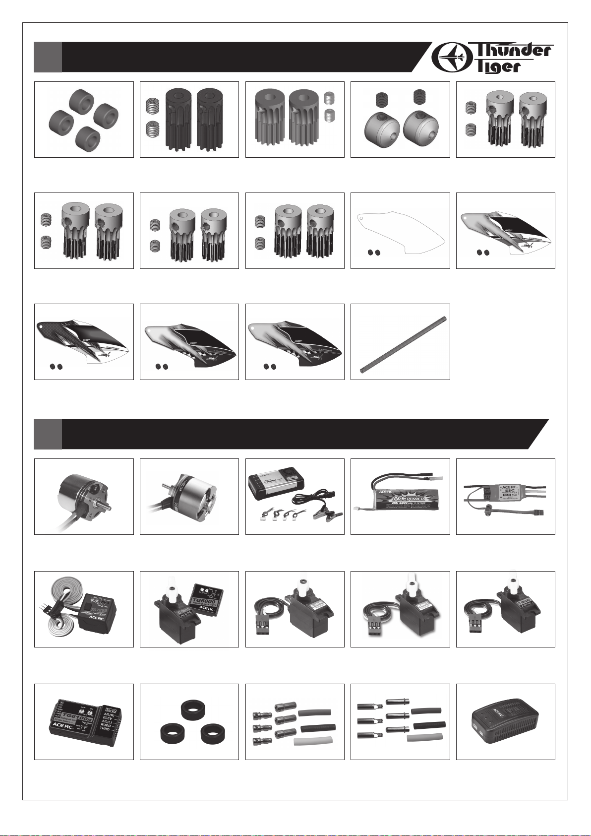
OPTION PARTS / 選配零件
PV0706
FLAP DAMPER(70°)
避震墊圈(70°)
PV0831
PINION 11T (d3.17)
驅動齒輪 11T(d3.17)
PV1244-C
FRP CANOPY(CORBON)
玻纖機殼(碳纖)
POWER & ELECTRONICS / 動力及電子配件
PV0730
PINION 10T(2)(FOR 2.3mm SHAFT)
驅動齒輪 10T
PV0832
PINION 12T
驅動齒輪 12T
PV1244-LY
FRP CANOPY(BLUE/YELLOW)
玻纖機殼(藍/黃)
PV0731
PINION 15T
驅動齒輪 15T
PV0833
PINION 14T
驅動齒輪 14T
PV1244-LG
FRP CANOPY(BLUE/GREEN)
玻纖機殼(藍/綠)
PV0828
SETTING WEIGHT
重鎚
PV1244
FRP CANOPY(UNPAINTED WHITE)
玻纖機殼
PV0825-T
CARBON TAIL BOOM
碳纖維尾管�
PV0830
PINION 11T (d2.3)
驅動齒輪11T (d2.3)
PV1244-G
FRP CANOPY(GREEN)
玻纖機殼(綠色)
2381
BL. MOTOR, OBL 29/35-10H
無刷馬達, OBL 29/37-10H
8079
TG7200 HEADING LOCK GYRO
TG7200 鎖定式電子陀螺儀
AQ0843
TG6100M GYRO W/E-CCPM MIXER
TG6100M 陀螺儀含混控版
2382
BL. MOTOR, OBL 29/37-10H
無刷馬達, OBL 29/37-10H
8073
TG6000GYRO W/C0915 SERVO
TG6000 陀螺儀+尾舵伺服機
AQ0835
ANTI-INTERFERENCE RING
防磁環
2532
Li-Po BATTERY E-CHARGER ELC 4
鋰電池充電器 ELC 4
8117
ACE MICRO SERVO,C1016
迷你伺服機, C1016
AQ0836
GOLD CONNECTORS(3.5mm)
鍍金端子(3.5mm)
2814
LI-PO BATT,3S1P/2200mAh/25C
鋰電池,
8131
ACE MICRO SERVO,C0915
迷你尾舵伺服機, C0915
AQ0837
GOLD CONNECTORS(4mm)
鍍金端子(4mm)
-54-
3S1P/2200mAh/25C
8041-H
SPEED CONTROL, ACE BLC-40
無刷速控器, ACE BLC-40
8139
ACE MICRO SERVO,C1016MG
迷你尾舵伺服機, C1016MG
2536 / 2536-E / 2536-U
T3AC BALANCE CHARGER
T3AC 平衡鋰電充電器
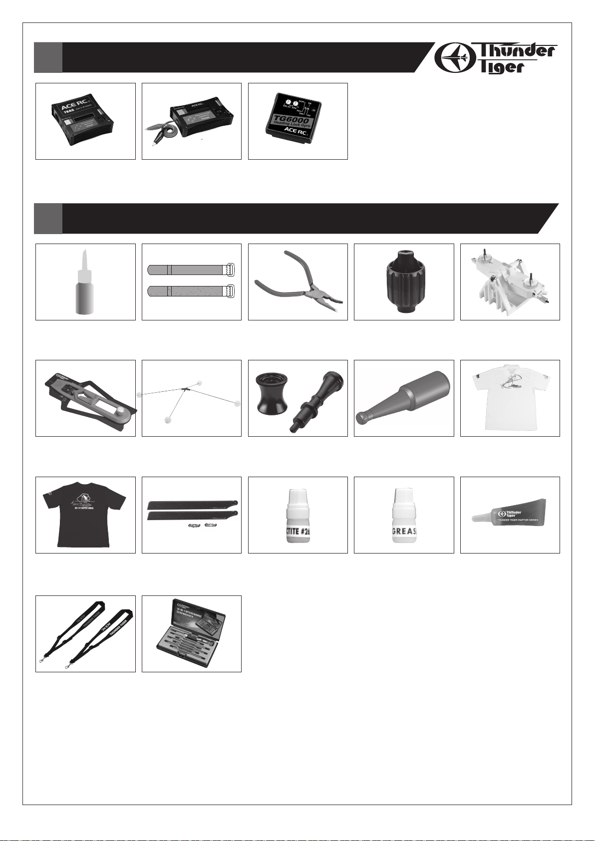
POWER & ELECTRONICS / 動力及電子配件
2537 / 2537-E / 2537-U
T6AC DIGITAL BALANCE CHARGER
T6AC雙輸入智能充放電器
ACCESSORY / 其他相關產品
PV0760
ANAEROBICS RETAINER, R48
缺氧膠, R48
1078
PITCH GAUGE
螺距尺
2538
T6 DIGITAL BALANCE CHARGER
T6 雙輸入智能充放電器
PV0835
VELCRO
束帶
1079
TRAINING GEAR
練習架
8072
TG6000 GYRO
TG6000 鎖定式陀螺儀
1075
BALL LINK PLIERS(D3.8mm)
連桿專用鉗(D3.8mm)
1080
ONE WAY BEARING RELEASER
單向軸承退出器
1076
BALL LINK WRENCH
單頭連桿鈑手
1198
BALL LINK REAMER
球頭絞刀 (3.8mm)
1077
BLADE BALANCER
主旋翼平衡器
1387
POPL-SHIRT(WHITE) SIZE:XS~2XL
POPL衫(白色) SIZE:XS~2XL
1388
T-SHIRT(BLACK) SIZE:XS~2XL
T恤(黑色) SIZE:XS~2XL
1389-R
1389-W
1389-W(White)
1389-R(Red)
NECK STRAP
發射機吊帶(白色、紅色)
3874
CARBON ROTOR BLADE,325mm
碳纖主旋翼組, 325mm
1197
14 IN 1 SCREWDRIVER SET
14 合1小型板手工具組
PV0268
LOCTITE #262 / T22
高強度防鬆劑(紅色) #262
-55-
PV0270
GREASE (FOR BEARING)
止推軸承潤滑脂(黑色)
PV0517
ONEWAY BEARING GREASE
單向軸承油脂,R50/90

EXPLODED VIEW / 爆炸圖檢索
PV0257
PV0783
PV0781
PV0829
PV0803
PV0236
MAIN ROTOR HEAD
PV0781
PV0837
PV0838
PV0807
PV0754
PV0755
PV0805
PV0804
PV0707
PV0801
PV0844
PV0805
PV0838
PV0722
PV0803
PV0837
PV0257
PV0236
PV0769
PV0829
PV0781
PV0783
PV0775
PV0802
PV0809
PV0727
PV0808
PV0802
-56-
PV0234
PV0702
PV0723
GEAR SET
PV0726
PV0727

EXPLODED VIEW / 爆炸圖檢索
PV1224
PV1223
PV1235
PV1247
PV1228
PV1231
PV1227
PV1230
PV1229
PV1225
PV1267
MAIN FRAME
PV1235
PV1267
2382
PV1240
SKID & MOTOR MOUNT
PV1235
PV0729
PV1244-Y
PV1226
PV0903
PV1224
-57-
PV0746
CANOPY

EXPLODED VIEW / 爆炸圖檢索
TAIL UNIT
PV0742
PV0770
PV0820
PV0777
PV0770
PV0781
PV0776
PV0781
PV0777
PV0739
PV1238
PV1237
PV0749
PV0814
PV0842
PV0742
PV0751
PV0751
PV0762
PV0752
PV0755
PV0739
PV0741
PV0823
PV0753
PV0755
PV0747
PV1156
PV0735
PV1234
-58-

SPECIFICATION / 規格表
ø745
ø156
640
ø315
209
120
Length / 全長:
Height / 總高度:
Width / 全寬:
Main rotor disc diameter / 主旋翼旋轉直徑:
Tail rotor disc diameter / 尾旋翼旋轉直徑:
Motor drive gear / 馬達驅動齒:
Main gear / 主齒盤:
Tail grive gear / 尾驅動齒盤:
Tail pulley / 尾傳動齒:
Gear Ratio / 齒輪傳動比:
Weight (w/o battery) / 全配重量 (不含電池):
640 mm (25.19 in)
209mm (8.2 in)
120mm (4.72 in)
745mm (28.46 in)
156mm (6.14 in)
13T
150T
124
14T
1:11.5:4.4
approx. 625g (22.04oz)
FEATURES / 特色
1. Super Rigid Carbon Frame & CNC Machined Aluminum Construction
2. Slim & Aerodynamic Pre-Painted Fiberglass Canopy
3. One-piece Low Gravity Molded Skid /Integrated Antenna Holder
4. 2-piece Reinforced Carbon Main Frame (1.5mm)
5. Integrated One-piece High-positioned Battery & ESC Tray
6. Adjustable Bell-Hiller Mixing Ratio
7. One-piece Machined Aluminum Mast Block /Servo Mount
8. Metal & Carbon Light Tail Case/ Metal Grips
9. Canopy With Integrated Heat Sink For Efficient Thermal Dissipation
10. Equipped With Lightweight Paddles for 3D (4.4gr)
1. 高剛性碳纖維及金屬結構主體
2. 原廠塗裝完成玻纖材質機頭罩
3. 一體式低重心腳架及天線組
4. 二片式強化碳纖維主側板
5. 整合式高置電池座及速控器座
6. 可調式混控比率旋翼頭組設計
7. 一體式金屬主軸軸承座及伺服機座
8. 金屬/碳纖維輕量化尾殼/金屬夾片
9. 高效率散熱孔設計機頭罩
10. 標準搭配3D版輕量化平衡翼
雷虎科技
THUNDER TIGER CORPORATION
www.thundertiger.com
C 2010
Printed in China
JK0239 V4
 Loading...