

Page 1

AAsssseemmbbllyy MMaannuuaall
1
Hughes 500 MD Scale Fiberglass Fuselage (TTR3834)
Distributed in North America by Ace Hobby Distributors,Inc.• 2055 Main Street,Irvine,CA 92614
Telephone:949.833.0088 • www.acehobby.com • E-mail:service@acehobby.com
Fuselage Length (less rotor):56" (1425mm)
Fueslage Width (less rotor):23.5"(595mm)
Full Equipped Weight:13~13.5 lbs (5900~6100g)
Specifications:
Warranty
This kit is guaranteed to be free from defects in material and workmanship at the date of purchase. It
does not cover any damage caused by use or modification. The warranty does not extend beyond the
product itself and is limited only to the original cost of the kit. By the act of building this user-assembled
kit,the user accepts all resulting in liability for damage caused by the final product. If the buyer is not
prepared to accept this liability,it can be returned new and unused to the place of purchase for a refund.
Notice: Adult Super vision Required
This is not a toy. Assembly and flying of this product requires adult supervision.
Read through this book completely and become familiar with the assembly and flight of this MD-500.
Inspect all parts for completeness and damage. If you encounter any problems,call us for help.
JK6001
Page 2

2
INTRODUCTION
PRE-ASSEMBLY NOTES
Congratulations on the purchase of one of our finest scale heli fuselage to date. This famous Hughes MD
500 (Military Defender),used as an antitank,multi-mission helicopter .Flown e xtensivel y during the Vietnam War
Era performing multiple missions under extreme conditions.
The venerable MD 500 has been replicated to exhibits this attack helicopter s' sleek details. The light fuselage
comes factory pre-painted with all necessary hardware.It is very easy to assemble and only takes you few hours
of enjoyable installation to put this scale body on your helicopter.
This replica MD is just like a real thing,hovering this MD that will definitely make you stand out on the flying
field.
Before beginning the assembly read the instructions thoroughly to give an understanding of the
sequence of steps and a general awareness of the recommended assembly procedures.
By following these instructions carefully and refer r ing to the corresponding pictures,the assembly of
your model will be both enjoyable and rewarding. The result will be a well built,easy to assemble scale
model,which you will be proud to display.
This MD-500 is designed for intermediate to advanced pilots,and this manual assumes a basic
knowledge of R/C model construction.
Before your assembly
1. Before you start to assemble this fuselage on your helicopter, we suggest you to first fine tune your
helicopter in the air.
2. Double-check all screws,then secure and Loctite all the loose screws.
3. The instruction manual is written for Raptor, if user should choose to install it on other branded
helicopters, then we would suggest to study thoroughly first the manual to see how it is installed on a
Raptor.
Before you begin,check the entire contents of your kit against the parts list and photos to make sure
that no parts are missing or damaged. This will also help you to become familiar with each component of
your model. If you find that any of the parts are either missing or damaged,(Customer s in North America)
please contact Ace Hobby Distributors, Inc.,Customer Service immediately for replacements.
Please read the entire manual before beginning construction.
Neither your dealer nor Ace Hobby Distributors, Inc., can accept kits for return if construction has begun.
Trial fit each part before gluing it in place. Make sure you are using the correct part and that it fits
well before assembling. No amount of glue can make up for a poor-fitting part.
TABLE OF CONTENTS
Introduction.................................................2
RecommendedTools & Materials............. 3
Item Y ou May Need.................................... 3
Parts Drawings............................................ 4-5
Parts Check List..........................................6
Assembly...................................................... 7
Test Flight..................................................... 14
MEMO...........................................................15
Page 3
3
RECOMMENDED TOOLS & MATERIALS
Adhesives:
Instant setting Cyanoacrylate adhesive (thin CA)
Slow setting Cyanoacrylate adhesive (thick CA)
10 Minute Epoxy (fast)
20-30 Minute Epoxy (slow)
Tools:
Model knife, 1/2” MASK tape
Small screwdrivers,medium screwdrivers
Scissors
Long nose pliers and diagonal cutting pliers
Drill and drill bits (1/16",5/64")
150 grid sand paper
Fine felt tip pen and soft lead pencil
Reamer
R/C System:
6 Channel Heli radio
GYRO system
Helicoptor:
Raptor 60~90 Suggested
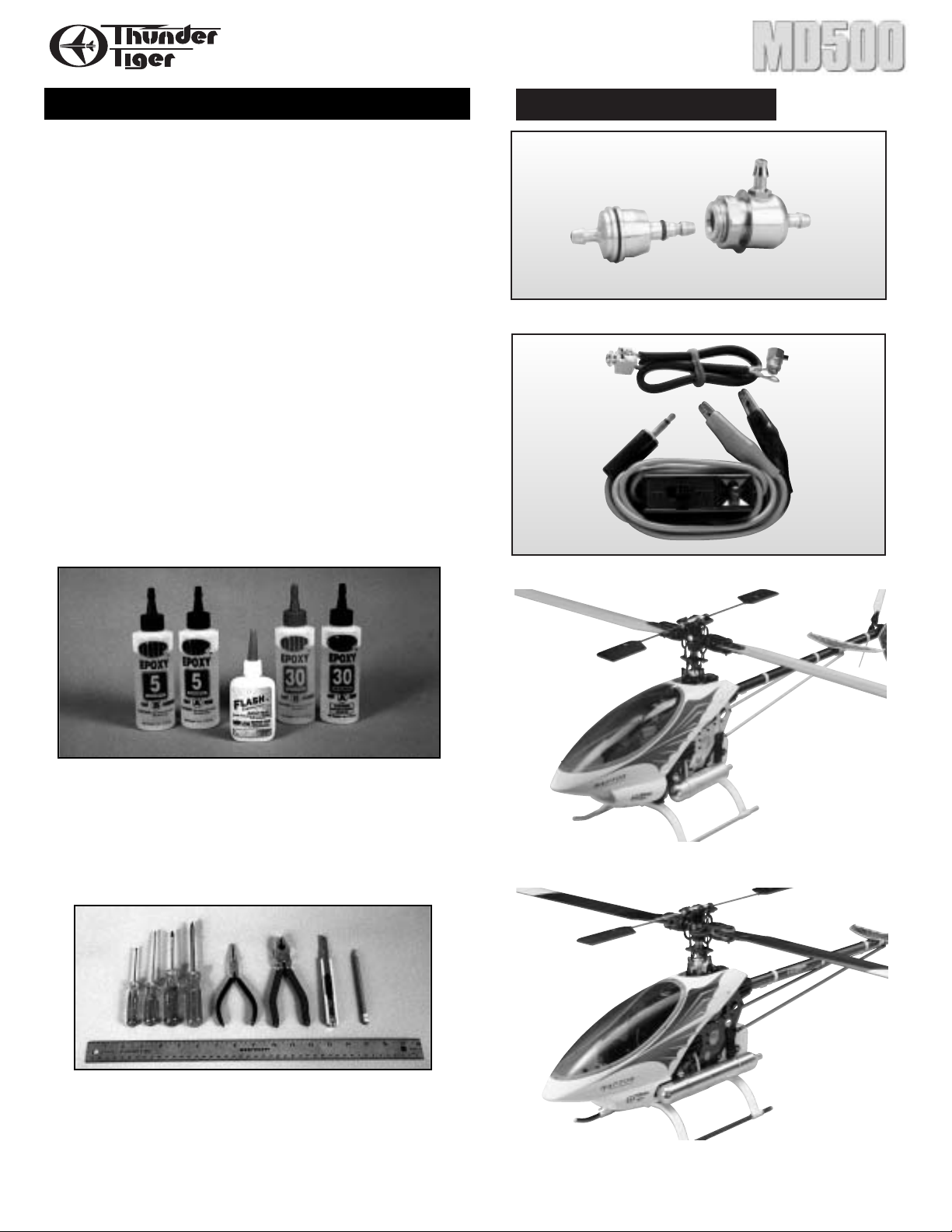
TTR1115 - Precision Fueler Valve
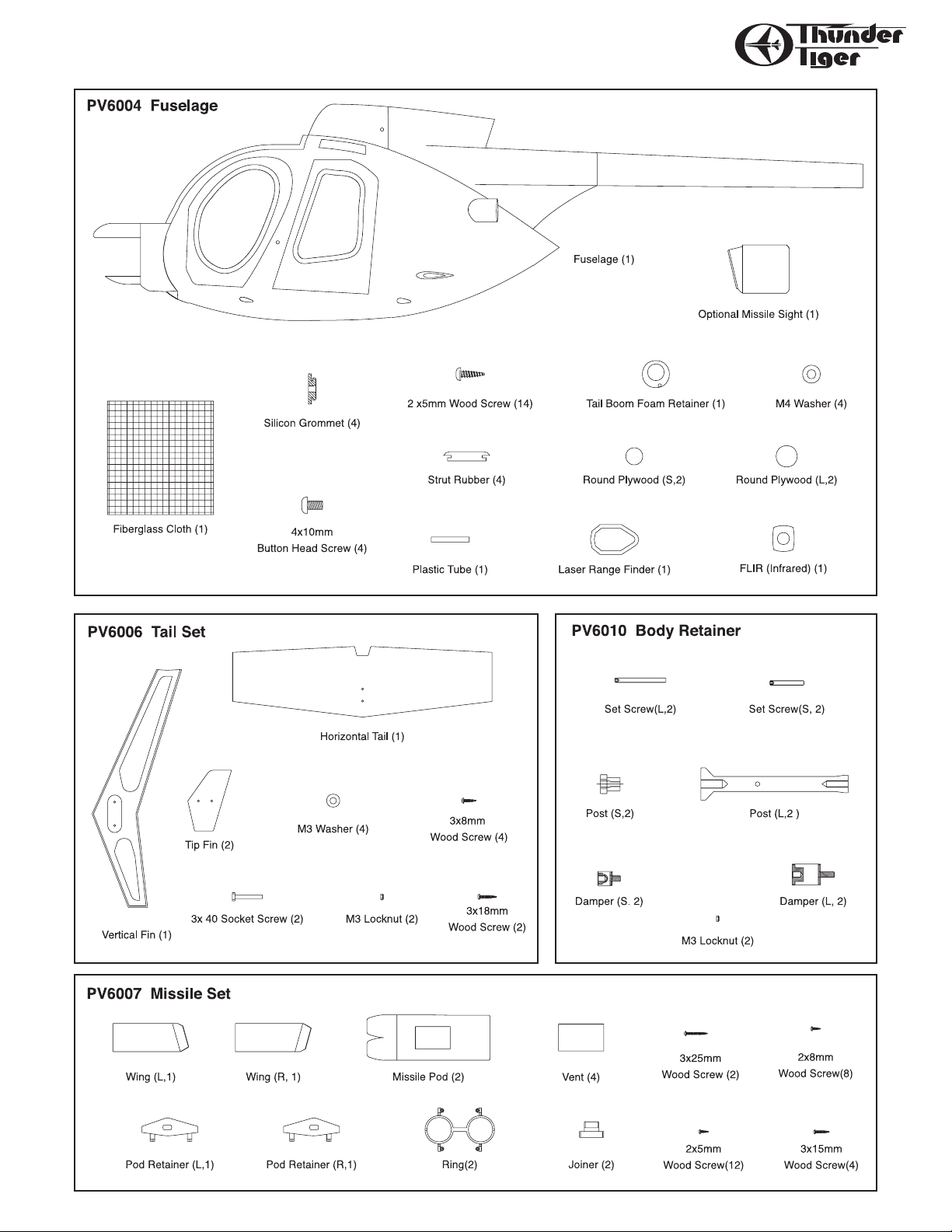
TTR2174 - Built in Glow Plug Extension Wire
TTR4870 - Paptor 60
TTR4890 - Paptor 90
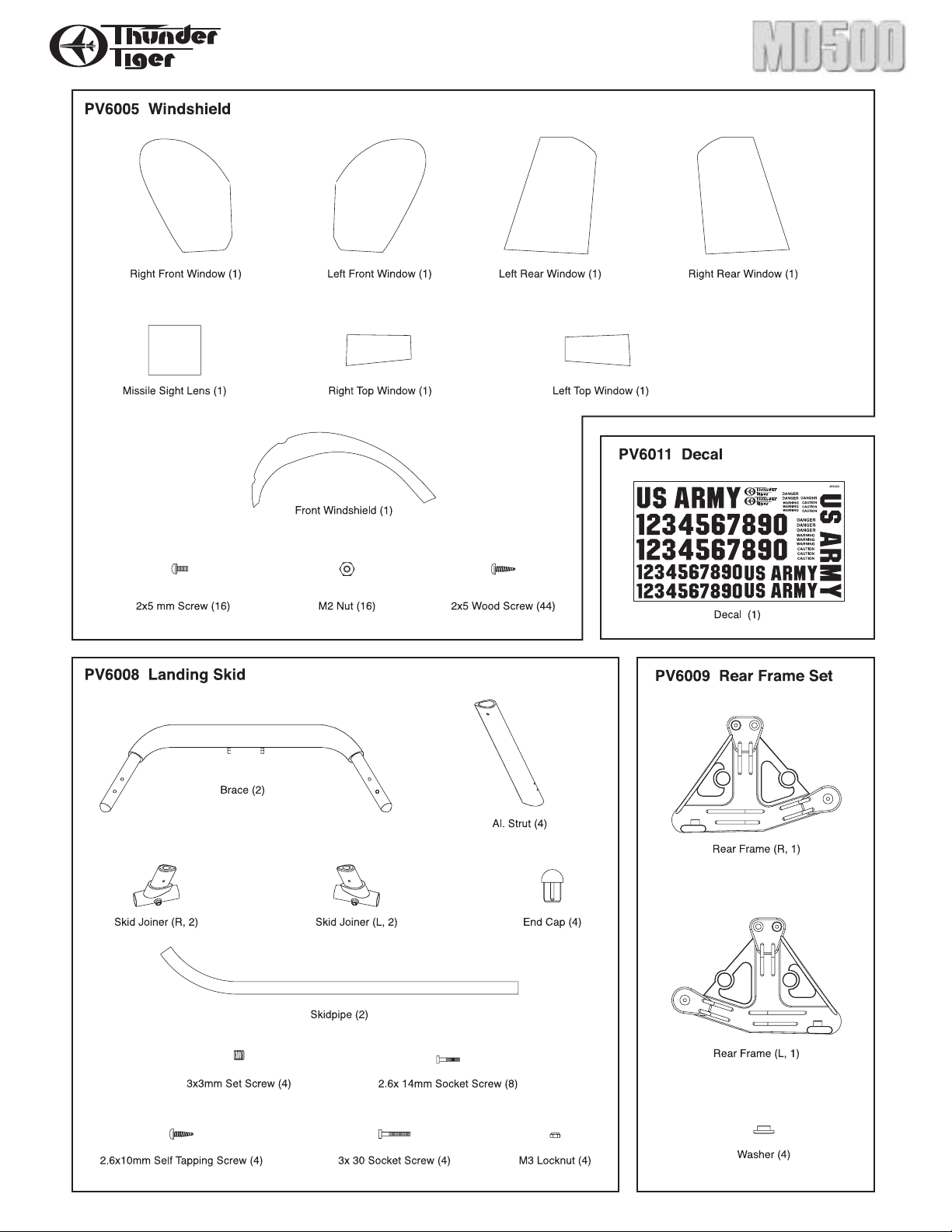
Adhesives - You will need two types of adhesives for
the MD-500 - Epoxy and Instant (cyanoacrylate)
adhesives. We recommend that you purchase both 5minute and 30-minute epoxy to cut down on assembly
time, but you can get by with only 30-minute epoxy if
time is not important.You will also need a small bottle of
both “Thick” and “Thin” instant C A adhesive.
Tools - Model assembly can be much easier if the
proper tools are used. Therefore, we have included in
our checklist to the left,a complete listing of all the tools
we used to assemble our prototype models. As you will
notice, many household tools can be utilized during
construction.
ITEMS YOU MAY NEED
Page 4
4
PARTS DRAWINGS
Page 5
5
Page 6

6
PARTS CHECK LIST
Missile Set
Wing (L,1)
Wing (R,1)
Missile Pod (2)
Pod Retainer (L,1)
Pod Retainer (R,1)
Ring(2)
Joiner (2)
Vent (4)
3x25mm Wood Screw (2)
3x15mm W ood Screw(4)
2x8mm W ood Screw(8)
2x5mm W ood Screw(12)
Body Retainer
Post (L,2 )
Post (S,2)
Set Screw(L,2)
Set Screw(S,2)
Damper (L,2)
Damper (S.2)
M3 Locknut (2)
Windshield
Front Windshield (1)
Right Front Window (1)
Kit Contents:
Fuselage
Fuselage (1)
Missile Sight (1)
Round Plywood (S,2)
Round Plywood (L,2)
Laser Range Finder (1)
FLIR (infrared) (1)
Tail Boom Foam Retainer (1)
M4 Washer (4)
Silicon Grommet (4)
Strut Rubber (4)
2 x5mm Wood Screw (10)
Plastic Tube (1)
Fiberglass Cloth (1)
Tail Set
Vertical Fin (1)
Horizontal Tail (1)
Tip Fin (2)
3x 40 mm Socket Screw (2)
3x18mm Wood Screw (2)
3x8mm Wood Screw (4)
M3 Washer (4)
M3 Locknut (2)
Left Front Window (1)
Right Rear Window (1)
Left Rear Window (1)
Right T op Window (1)
Left T op Window (1)
Missile Sight Lens (1)
2x5 mm Machine Screw (16)
M2 Nut (16)
2x5 mm Wood Screw (48)
Mask T ape (1)
Landing Skid
Brace (2)
Al.Strut (4)
Skid Joiner (R,2)
Skid Joiner (L,2)
End Cap (4)
3x 30 mm Socket Screw (4)
3x3mm Set Screw (4)
2.6x 14mm Self Tapping Screw (8)
2.6x10mm Self Tapping Screw (4)
M3 Locknut (4)
Rear Frame Set
Rear Frame (L,1)
Rear Frame (R,1)
Washer (4)
Page 7

7
Assembly
1. Locate four Round Plywood pieces, glue the same sized
pieces together as shown.
2. Position the OMS (Optical Missile Sight) in place then
epoxy the two doubled round plywood inside the OMS.
Glue one side first then the other.Make sure the OMS can
be rotated.You may install a micro camera or servo making
sure that it can really do a mission at your command.If not,
then you can just epoxy the OMS in place firmly.
3. Locate the Sight Lens,position it in place, then drill 1/16"
(1.5mm) holes at the four corners.Secure the lens in place
with four 2x5mm Wood Screws.
4. Note the orientation of the wing tip and trail making sure
it can fit two Wings in the wing mount. Ascertain the two
wings are at same dihedral angles and the trailing/leading
edge of two wings are in line with each other. Adjust it
until you obtain a satisfactory result, then use pencil to
make marks on the wing at both sides as guidelines.
5. Remove the Wing to sand away the paint base on the
guideline you drew, this is the glue area that you could
sand with 150 grid sand paper to enhance the adhesion.
Remove the paint in the wing mount,you may use hobby
knife to scratch the surface in the well.
Page 8

8
6. Fit the wing in place again, drill two 5/64"(2mm) holes
through the wing mount to the wing from the inside of the
fuselage. Remove the wing again,apply epoxy at glue area
and secured it with two 3x15mm Wood Screws. Either
wipe off the excess epoxy or use masking tape to tape the
guideline to keep the wing clean after the masking tape
removal.
7. Repeat the same procedure on the other wing,make sure
the two wings are at same dihedral angles.If you see from
the top the trailing/ leading edge should be in line with
each other.
8. Locate the Laser Range Finder, position it right after the
Windshield at the center bottom of fuselage. Drill
1/16"(1.5mm) holes and secure it with six 2x5mm Wood
Screws.
9. Locate the molded marks for landing strut and engine
cooling openings at the bottom of the fuselage. Note these
marks are only for reference of Raptors,shall you install it
on other branded helicopters then you will have to find
out the correct opening position for landing strut before
you drill or trim the fuselage.
Note: For Raptor Owners, it is recommended to offset by
2mm to the center line when you trim the landing skid
opening. This will get more space between the collective
pitch frame and windshield where servo horn and ball link
might contact.
Center Line
Page 9

10.Locate four Rubber Rings, trim away the flashing and
center portion.Place the Rubber Rings at the four landing
strut openings. It might be necessary to trim the opening
larger to fit the rubber ring with the inserted Aluminum
strut.For the rear strut opening,you may cut the ring for
easier access.
11.Put the scale fuselage aside for a moment and get your
heli prepared. For Raptor owners, please remove the
Landing Skid, Muffler, Tail Fins, Boom Supports and Tail
Rotor Assembly. Locate the new Rear Frames,which are
specially designed for this MD fuselage. Use the new
washers and secure the Rear Frame in place with the
same screws you used previously. Also use the same
screw and locknut to secure the Rear Frame at the tail
boom mounting hole. Use the same Tank Rubber
grommets and install the Fuel Tank.
9
12.Assemble the Landing Skid as shown.Temporarily install
the Brace under the side frame. Adjust the Landing Skid
as shown and make sure it sits on the table firmly. Secure
the Joiner & Skid Pipe with the furnished 3x3mm Set
Screws. Do not over-tighten the setscrews;just make sure
the skid pipe will not rotate. Then secure the Joiner and
the Aluminum Strut with 2.6x10mm Self-Tapping Screws.
13.Remove the landing skid assembly from Heli. Remove the
brace from the aluminum strut. Do not remove the strut
and skid pipe as they are already adjusted and secured.
Apply masking tape on the strut that is going to make
contact with the fuselage, since the masking tape will
protect the paint from scratching. Place the brace on the
fuselage and install the strut and skid pipe onto the brace.
You may apply Vaseline on rubber ring to increase the
lubrication for easier installation.
Page 10
14.Secure the Aluminum Strut and Brace with 2.6x14mm
Socket Screws. Hint: Install the left Aluminum Strut
Assembly and Brace first ( Left side is the side of the
fuselage with Optical Missile Sight). Pull the brace out and
secure the socket screws then push it back and pull the
right side out then install the right aluminum strut
assembly.
15.Before fitting your helicopter into the fuselage, you may
trim all Windows and trails to better fit them into the
fuselage.It might be necessary to trim the FRP fuselage to
match the windows as well.Once you obtain satisfactory
result, proceed to drill 1/16"(1.5mm) openings through
the fiberglass the fuselage and window and secure the
window with 2x5mm Wood Screws. After finishing all the
windows, remove all the windows and clean the inside
fuselage entirely. (You can skip the rear side window for
easy operation)
10
16.Trial sit on the landing skid assembly. For Raptor owner,
position the Front Windshield in place and check if the
ball links on aileron servo horn contacts the front
windshield when it is in maximum positive pitch.Lower
the Raptor by enlarging the landing strut opening to the
fuselage center liner if the servo horn contacts the
windshield. It might be necessary to try several times
before obtaining a desirable result.
17.If you use Raptor 60 then it is required to trim off the
fuselage tail for about 1"( 2.5cm ). However, it is not
necessary for those using the 80/90 conversion kit, R90
STD Kit or R90 SE Kit since the tail gear case is longer than
the fuselage tail.Install the tail rotor assembly in place and
check if holes on the landing brace matches the side
frame landing skid-mounting holes. If it cannot reach the
holes then trim the tail until it is able to do so. Unthread
the ball link, insert a Plastic Tube then thread the ball link
back to pushrod at the original position.
Page 11

11
18.Remove the tail rotor assembly once again and proceed to
extract the Raptor from fuselage. Replace a M3 Locknut
from the old body post. Remove the socket screws and
replace the long setscrews,then secure the new retaining
post in place. The upper post goes with long setscrew and
the lower post goes with short setscrew. Remember to
apply Loctite then secure the posts firmly. Place the
Raptor into the fuselage again, the long post should be
located between front and rear window where we will
drill hole later. If not,try to move the Raptor backward by
trimming the strut opening and trial fit it again.
19.Locate a sponge as the Tail Boom Retainer, install the
sponge on the tail boom section where the plastic tube
for the sponge insertion. Be careful not to apply any glue
inside the plastic tube and make sure the pushrod can
move freely. Push the sponged tube into the fuselage tail
and make sure there is no binding of the pushrod
movement and the heli sit on the landing brace just right.
Glue the sponge inside the fuselage tail with CA.
Note: do not glue sponge and tail boom in case you had to
remove the heli from fuselage. Install the tail rotor assembly
in place firmly and snap on the ball link.
20.Secure the helicopter onto the landing brace with four
3x30mm Socket Screws and M3 Locknuts.Secure the rear
brace first then the front.
21.Secure the Vertical Fin in place with two 3x40 Socket
Screws,two M3 Washer s and two M3 Locknuts.
Page 12

12
22.Trial fit the Horizontal Tail onto the vertical fin,note that
flat surface should be facing up and the other side with
the air foil facing down. It might be necessary to file/sand
the contact area on the vertical fin so that they make
perfect contact. Apply epoxy at the contact area and
make sure it is perpendicular after securing it with two
3x18mm Wood Screws and two M3 Washers. Secure two
vertical Tip Fins onto horizontal tail with four 3x8mm
Wood Screws.
23.Install the big Damper in place as shown then drill 3/8"
(9mm) hole.Never drill the hole on the molded mark as it
is only for reference, please drill the hole and aim to the
damper screw hole.
24.Remove the damper temporarily and insert the Silicon
Grommet from the inside fuselage then re-install the
damper again. Note the bigger diameter side should be
facing the Damper. Secure the fuselage with 4x10mm
Button Head Screw and M4 Washer. Do the same
procedure at the other side.
25.Locate the small Damper and do the same way you did for
the last two steps.
26.Secure the fuselage with 4x10mm Button Head Screw and
M4 Washer as shown.
Page 13

13
30.Locate the Joiner and insert it into the pod retainer,next
trial fit the missile pod assembly onto the wing. Make sure
two missile pod are angled just right, if not then trim it
until it will. Remove the missile pod assembly then apply
epoxy at the joint area in the wing then secure the wing
with 3x25mm Wood Screw. Make sure again that the two
missile pods are at same angle.
31.Install the muffler on the Raptor and try to install a
diverter. It is recommended to drill an exit hole at the
bottom of the fuselage and it will enable your beautiful
MD to be less oily.If you do not care about the smoke oil
then you may customer built a Y splitter and exhaust at
the two exhaust vent to obtain a more scale-like look.
27.Locate the FLIR and place it at the center of the tail
section either at the top or bottom. Drill four 1/16"
(1.5mm) mounting holes and secure the FLIR with four
2x5mm W ood Screws.
28.Locate the Pod Retainer and center it on the missile pod
(the missile pod with square molded line should face
down). Drill 1/16" (1.5mm) holes then secure it with
2x8mm Wood Screws.Note the orientation of the retainer.
29.Locate the Vents (fiberglass tube) and rings, position the
two vents at the tail of missile pod then secure the ring on
the tail with four 2x5mm Wood Screws. The vents should
stay firmly in the place. Drill 1/16"(1.5mm) holes on the
vent then secure the vent firmly with 2x5mm wood
screw.
Front
Rear
Page 14

14
32.You will have to install the remote glow plug adaptor
(TTR3803). With the opening for engine cooling located
at the bottom of the engine,you can either use the glow
starter from the opening or install a Built in Glow Plug
Extension Wire (TTR2174) and secure the connector on
the fuselage for easy glow ignition. Also suggested is the
use of Precision Fueler Valve (TTR1115) which is very
convenient for both re-fueling or de-fueling and could filer
the fuel when fueling.
33. Install all the windows on. It is recommended to secure
the front windshield first then the front side windows.
You may skip the installation of the rear side windows,as
it is easier for you in case of tuning engine or adjustment.
Shall you decide to install the rear side window then you
might need to cut a hole for your index finger's insertion
allowing easier securing of the windows. Remember if
rear windows are installed,a needle valve extension and a
small hole for tuning the mixture metering screw ( idle
screw) are required. Even the RX battery on/off switch
should be installed on fuselage.
Test Flight
1. When hovering you MD, try to keep rotor speed at
approximately 1350~1400 RPM.The higher RPM will cause
vibration at the small tip fins.
2.Check the helicopter and fuselage to see if there is any loose
screw after each flight.
3. It is easy to get nose up in speed flight, please trim the
elevator down when swith on the Idle.Suggest to off set at
about 15%~20%.
Page 15

MEMO
Page 16

16
THUNDER TIGER CORP . www.thundertiger.com
Introducing the pinnacle heli of the Raptor family,
the RAPTOR 90 SE. Designed and engineered by the
world-renowned F3C champion Mr. Shigetada Taya.
Thanks to all the feedbacks provided by Raptor
owners and customers worldwide, Thunder Tiger
heli design team has successfully combined today's
advanced technologies with previously successful
designs, R90 SE is the machine that everyone has
ever dreamed of.
Additional to R90, the R90 SE is a value-added
machine utilizing all the desired Hop-Up parts. R90
SE is only available in kit version without engine.
Specification:
Full Length of Fuselage: 1410mm(55.5")
Full Width of Fuselage: 190mm(7.5")
Total Height: 476mm(18.75")
Main Rotor Dia: 1580mm(62.25")
Tail Rotor Dia: 260mm(10.25")
Gear Ratio: 8.45:1:4.6
Fully Equipped Weight: 4650g(10.65lbs)
90 CLASS RC HELI
No.4890 R90 SE Key Features:
* Metal Button Head Main Rotor Hub
* Metal Grips
* Metal Swashplate
* Metal Washout Base
* Metal Side Frame Stiffener
* Metal Cooling Fan
* Metal Fork
* Metal Upper/Lower Bearing Block
* Metal Elevator Control Lever
* Metal Flybar Control Arm
* Carbon Graphite Collective Control Arm Set
* Carbon Side Frames
* Carbon Tail Fins
* Carbon Tail Boom
* Carbon Tail Boom Support
* Carbon T orque Tube
* 550 cc Fuel Tank
* Header Tank
* New Decal
PRO-90H(R) ENGINE
 Loading...