


TC7210-dNZ

Page 1 / 91
manual de fabricante
del cablerouter
Technicolor TC7210

Page 2 / 91
Safety Instructions
Using equipment safely
Your Cable Modem Gateway product has been manufactured to meet European and local safety
standards, but you must take care if you want it to perform properly and safely.
It is important that you read this booklet completely, especially the safety instructions below.
Equipment connected to the protective earth of the building installation through the mains connection or
through other equipment with a connection to protective earth and to a cable distribution system using
coaxial cable, may in some circumstances create fire hazard. Connection to a cable distribution system
has therefore to be provided through a device providing electrical isolation below a certain frequency
range (galvanic isolator, see EN 60728-11).
If you have any doubts about the installation, operation or safety of the product, please contact your
supplier.
To avoid the risk of electric shock
Disconnect the Cable Modem Gateway product from the mains supply before you connect it to (or
disconnect it from) any other equipments. Remember that contact with Mains can be lethal or causes
severe electric shock.
Never remove the product cover. Should the product fail, contact the Customer Service to arrange
repair or service.
Never allow anyone to push anything into holes, slots or any other opening in the case
Do not block the ventilation slots; never stand it on soft furnishings or carpets
Do not put anything on it which might spill or drip into it (e.g. Lighted candles or containers of
liquids). Do not expose it to dripping or splashing. If an object or liquid enters inside the Cable
Modem, unplug it immediately and contact the Customer Service.
Do not store the Cable Modem Gateway product in excessively hot, cold or damp conditions. It is
intended to operate at an ambient temperature of less than 35 degrees Celsius and a maximum
humidity level of 70%. In case of a storm, it is recommended that you unplug the product from the
mains and from the PC set or other equipment.
Leave the mains socket accessible so that you can unplug the set quickly
Telephone jacks Line 1 and Line 2 must not be connected to outside wiring.
Connecting to the mains supply
This appliance is designed to operate in the rated voltage 100 ~ 240 VAC.
If you are in any doubt about the mains lead, the plug or connection, please consult the Customer
Service.
Only the power adapter supplied with the product has to be used.
Ensuring optimum performance
Leave 7cm to 10cm around the appliance to ensure that proper ventilation gets to it.
Do not store your appliance on its side (if not allowed)
To clean the appliance, use a dry, clean soft cloth with no cleaning solvent or abrasive products. Clean
the ventilation openings regularly.

Page 3 / 91
Limiting the Human Body Exposure to the Electromagnetic Fields
Under normal use condition the user shall keep at least 20cm distance from the Cable Modem Gateway
product.
Environmental considerations
This symbol means that your inoperative electronic appliance, and used battery when
applicable, must be collected separately and not mixed with the household waste. The
European Union has implemented a specific collection and recycling system for
which producers' are responsible.
This appliance has been designed and manufactured with high quality materials and
components that can be recycled and reused. Electrical and electronic appliances are
liable to contain parts that are necessary in order for the system to work properly but
which can become a health and environmental hazard if they are not handled or
disposed of in the proper way. Consequently, please do not throw out your
inoperative appliance with the household waste.
If you are the owner of the appliance, you must deposit it at the appropriate local
collection point or leave it with the vendor when buying a new appliance.
- If you are a professional user, please follow your supplier's instructions.
- If the appliance is rented to you or left in your care, please contact your service
provider
Please help us protect the environment in which we live
Energy savings - You have a role to play…
Learn how you can use and explore ways for using your electronic equipment
The user manual detailed useful information on all the features of your product but also
on energy consumption performances.
We strongly encourage you to carefully read the notice before putting your equipment
in service to get the best service it can offer you.
By working together, we can reduce the impact we have on our earth!
Main technical specifications
General
Operating voltage
100 ~ 240 VAC
Typical Power consumption
24 W max
Power consumption in
networked Standby
<11.82W
Dimensions (W x H x D)
197mm x 138mm
Operating temperature range
0 – 40 °C
Storage temperature range
-20 – 70 °C
AC adapter (or plug-in
adapter) type
ADAPTER 24W 12VDC/2A

Page 4 / 91
Connections
DC input
12V/ 2A
Cable input
1xCoaxial cable connector
USB input
1x 2.0 USB connector
Phone plugs
2xRJ11
Ethernet plugs
4xRJ-45
Marking information
This symbol on your set guarantees that your product complies with the European
Directive 1999/5/EC on Safety, Telecom, Electromagnetic Compatibility, with the
2009/125/EC Directive on Energy related Products and the Directive 2011/65/EU on the
restriction of the use of certain hazardous substances in electrical and electronic equipment.
This equipment is intended to be used indoor in a residential or office environment. This
equipment may by operating in Europe
The CE Declaration of Conformity is available on the Website www.technicolor.com
Responsible Party: Technicolor Connected Home Rennes
975, Avenue des Champs Blancs CS17616
35576 Cesson-Sévigné Cedex
France

Page 5 / 91
Revision History ............................................................................. ¡Error! Marcador no definido.
Chapter 1: Connections and Setup ....................................................................................... 8
Turning on the Wireless Voice Gateway ................................................................................ 8
Introduction ........................................................................................................................ 8
Wireless Voice Gateway Features ...................................................................................... 8
What’s on the CD-ROM .................................................................................................... 9
Computer Requirements ................................................................................................... 9
Wireless Voice Gateway Overview....................................................................................... 10
Front Panel ..................................................................................................................... 10
Rear Panel ...................................................................................................................... 12
Wall Mounting ................................................................................................................ 14
Relationship among the Devices ........................................................................................ 15
What the Modem Does ................................................................................................... 15
What the Modem Needs to Do Its Job .............................................................................. 15
Contact Your Local Cable Company ................................................................................ 16
Connecting the Wireless Voice Gateway to a Single Computer ............................................ 16
Attaching the Cable TV Wire to the Wireless Voice Gateway ............................................ 17
Installation procedure for connecting to the Ethernet interface ....................................... 18
Telephone or Fax Connection ......................................................................................... 19
Chapter 2: WEB Configuration ............................................................................................ 20
Accessing the Web Configuration ...................................................................................... 20
Outline of Web Manager ................................................................................................. 21
Warning message to change the password ..................................................................... 22
Gateway – Status Web Page Group ..................................................................................... 23
1. Software .................................................................................................................... 23
2. Connection................................................................................................................ 24
3. Password ................................................................................................................... 25
4. Diagnostics ............................................................................................................... 27
5. Event Log .................................................................................................................. 28
6. Initial Scan ................................................................................................................ 29
7. Backup/Restore ......................................................................................................... 30
Gateway – Network Web Page Group .................................................................................. 31

Page 6 / 91
1. LAN ............................................................................................................................ 31
2. WAN ........................................................................................................................... 32
3. Computers ................................................................................................................. 33
4. DDNS - Dynamic DNS service ..................................................................................... 34
5. Time .......................................................................................................................... 35
6. FTP Diagnostics .......................................................................................................... 36
7. Port-base Passthrough ............................................................................................... 37
Gateway – Advanced Web Page Group ................................................................................ 38
1. Options ...................................................................................................................... 38
2. IP Filtering .................................................................................................................. 40
3. MAC Filtering ............................................................................................................. 41
4. Port Filtering .............................................................................................................. 42
5. Forwarding ................................................................................................................. 44
6. Port Triggers .............................................................................................................. 47
7. DMZ Host ................................................................................................................... 49
8. RIP (Routing Information Protocol) Setup .................................................................... 50
Gateway – Firewall Web Page Group ................................................................................... 51
1. Web Content Filtering ................................................................................................. 51
2. TOD Filtering .............................................................................................................. 52
3. Local Log ................................................................................................................... 53
4. Remote Log ................................................................................................................ 54
Gateway – Parental Control Web Page Group ...................................................................... 55
1. Basic .......................................................................................................................... 55
Gateway – Wireless Web Page Group .................................................................................. 56
1. Radio ........................................................................................................................ 57
2. Primary Network ........................................................................................................ 59
3. Access Control .......................................................................................................... 66
4. Advanced .................................................................................................................. 67
5. Bridging .................................................................................................................... 69
6. 802.11 Wi-Fi Multimedia: .......................................................................................... 70
Gateway – USB Web Page Group ......................................................................................... 72

Page 7 / 91
1. Media Server ............................................................................................................. 72
2. USB Basic settings ..................................................................................................... 73
3. Approved Devices settings ........................................................................................ 74
4. Stroage Basic ............................................................................................................. 75
5. Storage Advanced ..................................................................................................... 76
VoIP – Basic Web Page Group ............................................................................................. 77
1. Basic LAN .................................................................................................................. 77
2. Hardware Info ........................................................................................................... 78
3. Event Log .................................................................................................................. 79
4. CM State ................................................................................................................... 80
Chapter 3: Networking ....................................................................................................... 81
Communications ............................................................................................................... 81
Type of Communication .................................................................................................... 81
Cable Modem (CM) Section ................................................................................................ 82
Networking Section ........................................................................................................... 82
Three Networking Modes ................................................................................................... 82
Cable Modem (CM) Mode ................................................................................................... 83
Residential Gateway (RG) Mode .......................................................................................... 84
Chapter 4: Additional Information ...................................................................................... 86
Frequently Asked Questions .............................................................................................. 86
General Troubleshooting ................................................................................................... 88
Service Information ........................................................................................................... 89
Glossary ............................................................................................................................ 90

Page 8 / 91
CHAPTER 1: CONNECTIONS AND SETUP
Turning on the Wireless Voice Gateway
After installing the Wireless Voice Gateway and turn it on for the first time (and each time the modem is
reconnected to the power), it goes through several steps before it can be used. Each of these steps is
represented by a different pattern of flashing lights on the front of the modem.
If there is no lighted LEDs on the front panel, check the power adapter plug-in the power jack and
connect to CM correctly.
Note: All indicators flash once before the initialization sequence.
If both DS and US LEDs are flashing, it means the Wireless Voice Gateway is automatically updating its
system software. Please wait for the lights to stop flashing. Do not remove the power supply or reset the
Wireless Voice Gateway during this process.
Introduction
Wireless Voice Gateway Features
Full Band Capture Front End.
Increases performance with 50% increase in CPU speed.
Adds Applications CPU to run Linux applications.
Supports DBDC (Dual Band, Dual Concurrent).
Lowers Power with Advanced Power Management.
Advanced Processor architecture.
High-Speed Memory architecture.
Integrated IPTV solution.
Excentis EuroDOCSIS 1.0/1.1/2.0/3.0 Standard Compliant.
EuroPacketCable 1.0/1.5 SIP Standard Compliant (must be upgradeable to EuroPacketCable 2.0
version)
Support Multiple Provisioning Mode.
4 ports Standard RJ-45 connector for 10/100/1000BaseT Ethernet with auto-negotiation and MDIX
functions; Support maximum Ethernet cable length up to 100m (Category 5).
2 ports RJ-11 Foreign Exchange Station (FXS) port for IP telephony; Support a maximum line length
between themselves and an end-receiver (handset, etc.) of up to 500 feet (AWG 26/0.4mm).
Support simultaneous voice and data communications.
USB: Support a maximum cable length up to 5m
One voice conversations in the FXS port with different CODEC:
G.711‐ulaw, G.711‐alaw, G.723.1, BV16, ILBC, G.726‐16, G.726‐24, G.726‐32, G.726‐40,
G.728, G.729, G.729E, G.729A, G.729B, TELEVENT, T.38
Default codecs: G.711‐ulaw, G.711‐alaw, BV16, ILBC, TELEVENT, T.38
Echo Cancellation.
Voice Active Detection (VAD).
DTMF detection and generation.
Comfort Noise Generation (CNG).
Support V.90 fax and modem services.
56 bits DES and 128 bits AES data encryption security.
SNMP network management support.
802.11a/b/g/n/ac supported, 20/40/80MHz bandwidth, supports 3 × 3 antennas for data rates up to
1.3 Gbps.
Fully IEEE 802.11a/b/g/n legacy compatibility with enhanced performance.
Support Web pages and private DHCP server for status monitoring.
The NTP (Network Termination Point) should be able to operate with an LF (Loading Factors) of at
least 100 LU.
TEL 1 and TEL 2 port are not connected on Hardware side.
Propane™ technology supported, enabling the connection of more Internet users without additional
network bandwidth.

Page 9 / 91
What’s on the CD-ROM
Insert the Wireless Voice Gateway CD-ROM into your CD-ROM drive to view troubleshooting tips, the
internal diagnostics, and other valuable information.
CD-ROM Contents:
Electronic copy of this user’s guide in additional languages (PDF format)
Adobe Acrobat Reader — application you can load to read PDF format, if you don’t have it
loaded already
Links to Technicolor web site
Euro-DOCSIS and Euro-PacketCable are trademarks of Cable Television Laboratories, Inc.
Computer Requirements
For the best possible performance from your Wireless Voice Gateway, your personal computer must meet
the following minimum system requirements (note that the minimum requirements may vary by cable
companies):
IBM PC COMPATIBLE
MACINTOSH**
CPU
Pentium preferred
PowerPC or higher
System RAM
16MB (32MB preferred)
24MB (32MB preferred)
Operating System
Windows* NT / 2000 / Me / XP /
Vista / Windows 7, Linux
Mac OS** 7.6.1 or higher
Video
VGA or better (SVGA preferred)
VGA or better (SVGA built-in preferred)
CD-ROM Drive
Required
Required
Ethernet
10BaseT , 100BaseT or 1000BaseT
10BaseT , 100BaseT or 1000BaseT
An Ethernet card makes it possible for your computer to pass data to and from
the internet. You must have an Ethernet card and software drivers installed in
your computer. You will also need a standard Ethernet cable to connect the
Ethernet card to your Wireless Voice Gateway.
Software
A TCP/IP network protocol for each machine
Microsoft Internet Explorer 4.0 or later or
Netscape Navigator 4.0 or later.
* Windows is a trademark of Microsoft Corporation.
** Macintosh and the Mac OS are trademarks of Apple Computer, Inc.
Page 10 / 91
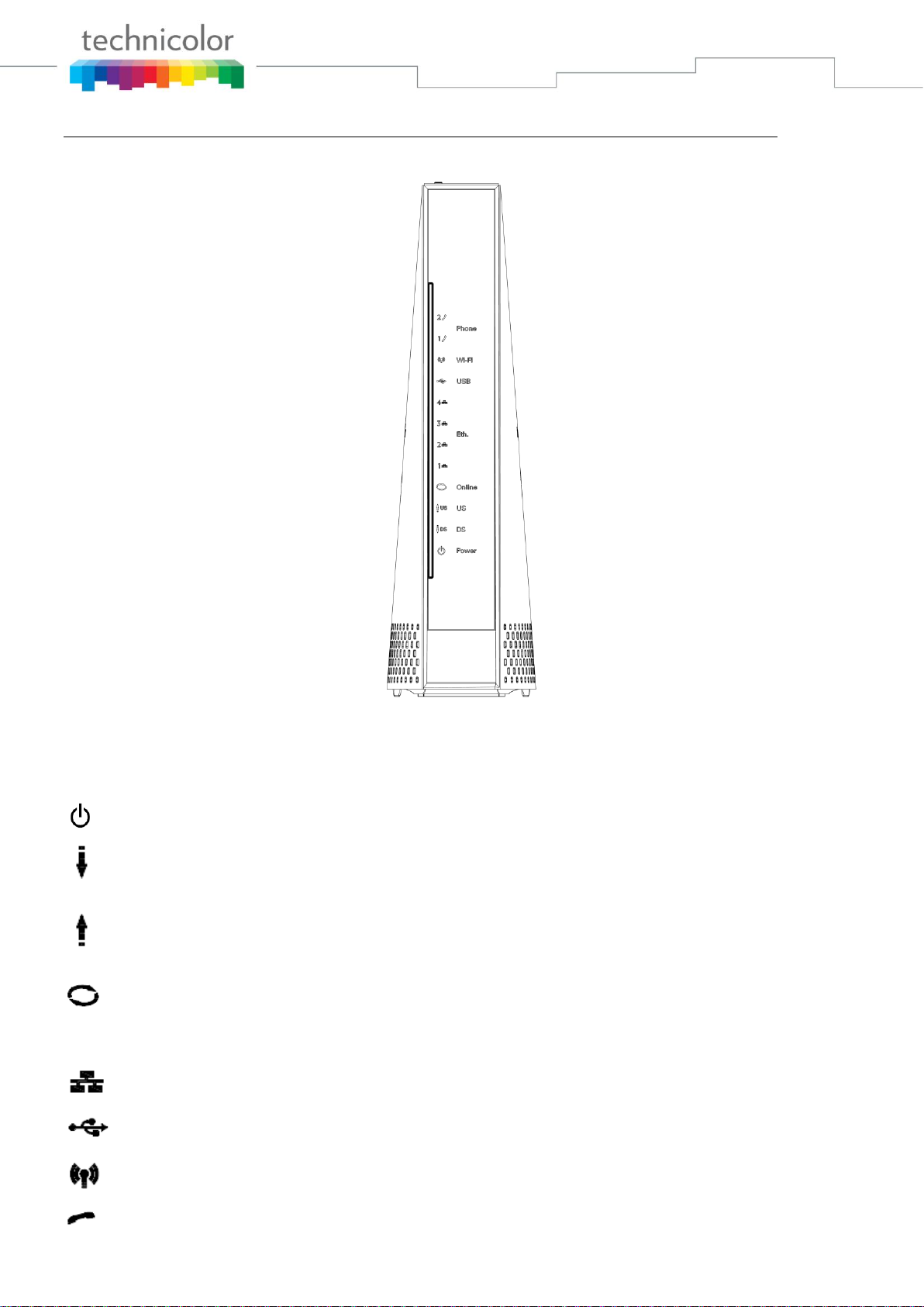
Wireless Voice Gateway Overview
Front Panel
Fig. 1-1 Front Panel
The following illustration shows the front panel:
Power - Indicates the Power status.
DS - Indicates the status of Data reception by the cable modem from the Network (Downstream
Traffic).
US - Indicates the status of Data transmission by the cable modem to the Network (Upstream
Traffic).
Online - Displays the status of your cable connection. The light is off when no cable connection is
detected and fully lit when the modem has established a connection with the network and
data can be transferred.
Ethernet - Indicates the state of Ethernet ports.
USB – Indicates the state of USB host connect.
Wireless - Indicates the traffic on the wireless network.
Phone - Indicates the status of the telephone Phone 1 and Phone 2.

Page 11 / 91
The lights on the front panel LEDs are described in the table below (from left to right):
ON = the LED is light, OFF = the LED is gray, FLASH = the LED is blinking.
TC7210
Power
Internet
Ethernet
USB
Wireless
TEL 1
TEL 2
Description
DS
US
Online
1
2
3
4
Boot-up
Operation
ON
ON
ON
ON
ON
ON
ON
ON
ON
X
ON
ON
Power on 0.25 sec
ON
0.25 second
ON
FLASH
FLASH
FLASH
X
X
X
X
X
X
X
X
From power ON to system initialization complete
ON
ON
ON
ON
X
X
X
X
X
X
X
X
Following system initialization complete to (before) DS scanning
1 second
DOCSIS
Start-up
Operation
ON
FLASH
OFF
OFF
X
X
X
X
X
X
X
X
During DS scanning and acquiring SYNC
ON
ON
FLASH
OFF
X
X
X
X
X
X
X
X
From SYNC completed, receiving UCD to ranging completed
ON
ON
ON
FLASH
X
X
X
X
X
X
X
X
During DHCP, configuration file download, registration, and
Baseline Privacy initialization:
DHCP status: 1 second ON and 1 second OFF,
TFTP status: 0.25 second ON and 0.25 second OFF
ON
ON
ON
ON
X
X
X
X
X
X
X
X
Operational (NACO=ON)
ON
FLASH
FLASH
OFF
X
X
X
X
X
X
X
X
Operational (NACO=OFF)
Channel
Bonding
Operation
FLASH
FLASH
FLASH
FLASH
X
X
X
X
X
X
X
X
Wait registration with all DS and all US – Lights Flash
sequentially from the right to left Minimum duration 3 seconds
X
X
X
X
OFF
X
X
X
X
X
X
X
From 1 to 4 DS, from 1 to 4 LEDs are ON
From 5 to 8 DS, From 1 to 4 LEDs are flashing
Duration 3 seconds
OFF
X
X
X
X
X
X
X
X
X
X
X
From 1 to 4 US, from 1 to 4 LEDs are ON.
FLASH
FLASH
FLASH
FLASH
X
X
X
X
X
X
X
X
Wait registration with all DS and all US – Lights Flash
sequentially from the left to right
MTA
initialization
ON
ON
ON
ON
X
X
X
X
X
X
FLASH
OFF
MTA DHCP
ON
ON
ON
ON
X
X
X
X
X
X
OFF
FLASH
MTA SNMP/TFTP
ON
ON
ON
ON
X
X
X
X
X
X
ON
ON
RSIP for NCS/Register for SIP
CPE
Operation
ON
X
X
X
OFF
ON
FLASH
OFF
ON
FLASH
OFF
ON
FLASH
OFF
ON
FLASH
OFF
ON
FLASH
OFF
ON
FLASH
X
X
No Ethernet / Wireless Link
Ethernet / Wireless Link
TX/RX Ethernet / Wireless Traffic
MTA
Operation
ON
<CM Normal Operation>
ON
ON
Both Lines On-Hook
ON
FLASH
ON
Tel1 Off-hook, Tel2 On-hook
ON
ON
FLASH
Tel1 On-hook, Tel2 Off-hook
ON
FLASH
FLASH
Both Lines Off-Hook
SW
Download
Operation
ON
FLASH
FLASH
ON
X
X
X
X
X
X
X
X
A software download and while updating the FLASH memory
LED Status when WPS State is
In-Progress
Green LED will blink with 2 sec On -1 sec OFF cycle
Success
Green LED will remain ON for 300 secs before turning OFF
Error"/"Timeout
Red LED will blink with 250 msec ON- 250 msec OFF cycle indefinitely
Session Overlap
Red LED will turn ON-OFF with 250 msec duration for 2 seconds followed by turning OFF
for 500 msec.
This cycle will repeat for a total duration of 120 seconds.
Table 1-1 LED behavior
Page 12 / 91
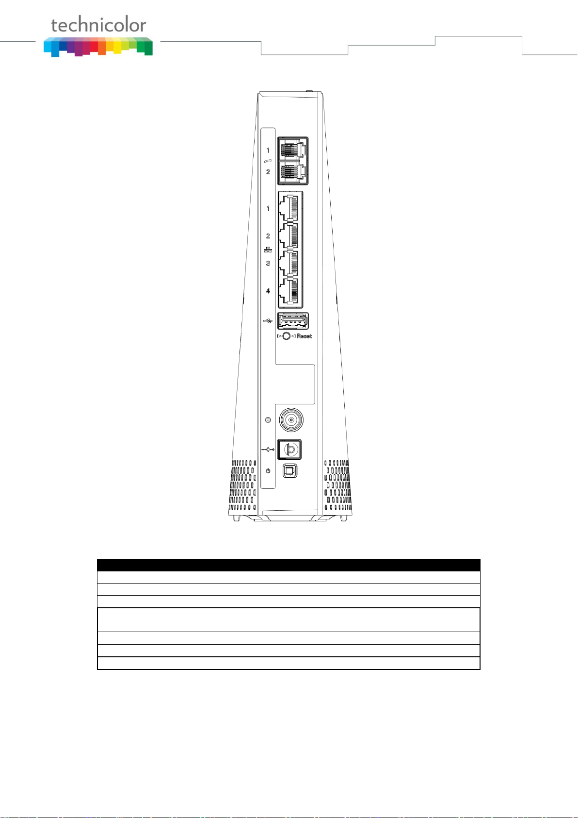
Rear Panel
Fig. 1-2 Rear Panel
Connector
Description
Power Switch
Power on, off the Cable modem.
Power Jack
Connector for DC12V.
Cable
Connector for the cable network.
Reset
To restart the modem or press over 5 seconds can
default the modem.
USB Host
USB 2.0 connector
Etherent
4 Gige Ethernet ports, RJ-45 connector.
Phone1/ Phone2
2 Phone RJ11 Connectors.
Table 1-2 Rear Panel description

Page 13 / 91
Side Panel for WPS
Fig. 1-3 Side Panel
WPS – Indicates the status of the WPS functionality.
WPS button: Wi-Fi Protected Setup
TM
. This button can be used to:
Secure the connection with another device (PC for example) using WPS protocol. A long press (press
2 more seconds) on the button allows you to enable the association of the modem with a PC or other
equipment.
After link establish. A short press on the button, switch on/off Wi-Fi.
Page 14 / 91
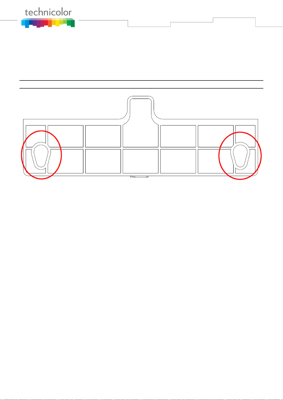
Wall Mounting
The number of the screw 2 pcs.
Direction for wall mounting: Tuner downward or leftward or rightward.
Dimension for the screw: diameter: 3.5mm; length: 10mm.
There are 2 slots on the underside of the CABKE MODEM that can be used for wall mounting.
Note: When wall mounting the unit, ensure that it is within reach of the power outlet.
Fig. 1-4 Wall Mounting
To do this:
1. For THE CABLE MODEM, ensure that the wall you use is smooth, flat, dry and sturdy
and use the 2 screw holes.
2. The unit can be to use solid concrete wall and/ or hard wood wall.
Tuner:
Note to CATV System Installer — The Coaxial cable shield shall be connected to the grounding
system of the building, as close to the point of cable entry as practical.
Page 15 / 91
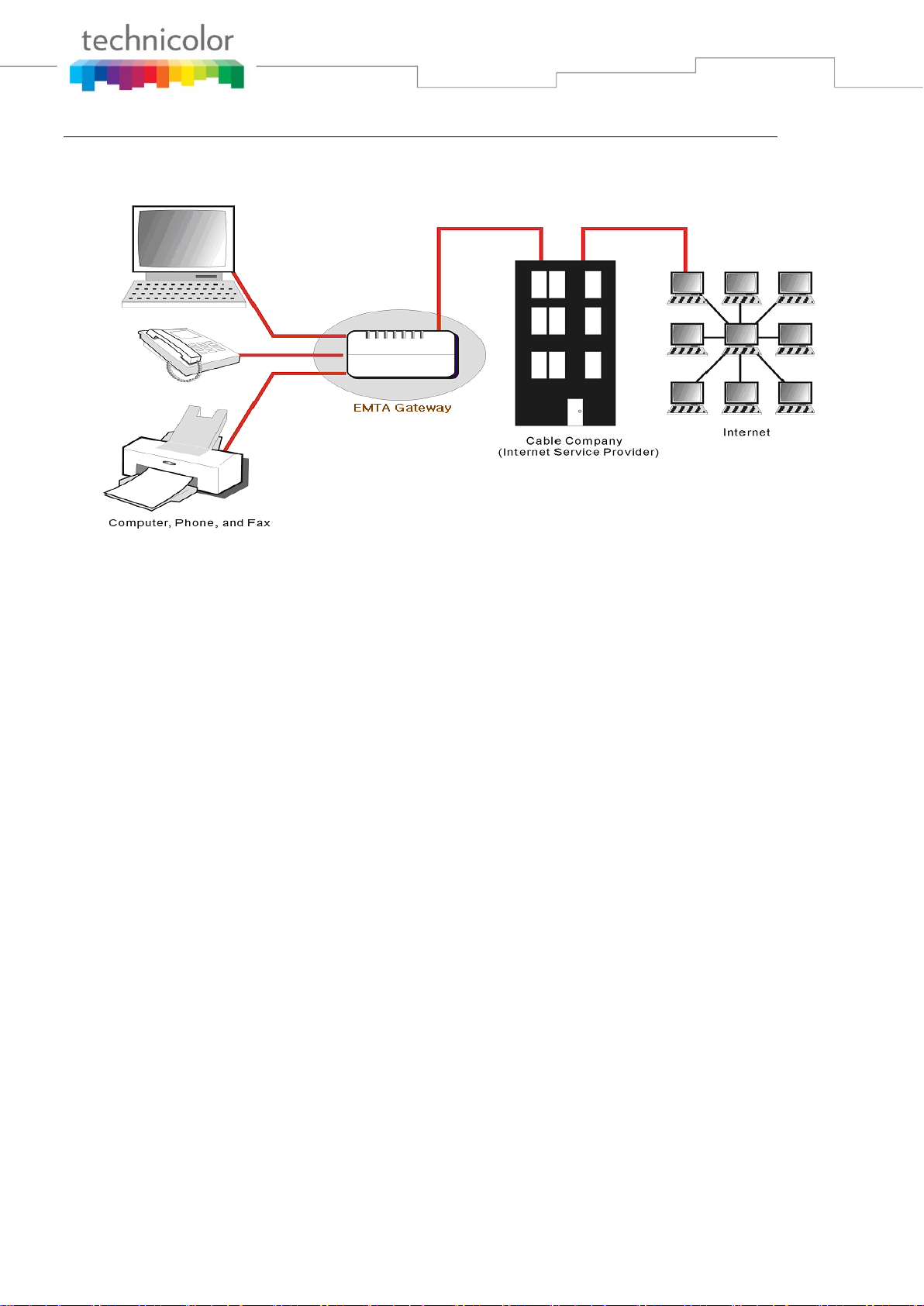
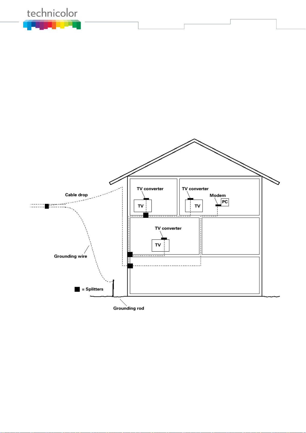
Relationship among the Devices
This illustration shows a cable company that offers DOCSIS/Euro-DOCSIS and PacketCable/Euro-
PacketCable compliant voice/data services.
Fig. 1-5 Connection overview
What the Modem Does
The Wireless Voice Gateway provides high-speed Internet access as well as cost-effective, toll-quality
telephone voice and fax/modem services over residential, commercial, and education subscribers on
public and private networks via an existing CATV infrastructure. It can inter-operate with the
PacketCable compliant head-end equipment and provide the IP-based voice communications. The IP
traffic can transfer between the Wireless Voice Gateway and DOCSIS/Euro-DOCSIS compliant head-end
equipment. The data security secures upstream and downstream communications.
What the Modem Needs to Do Its Job
The Right Cable Company: Make sure your local cable company provides data services that use
cable TV industry-standard DOCSIS/Euro-DOCSIS compliant and PacketCable/Euro-
PacketCable compliant technology.
The Internet/Telephony Service Provider (ISP/TSP): Your cable company provides you access
to an Internet Service Provider (ISP) and Telephony Service Provider (TSP). The ISP is your
gateway to the Internet and provides you with a pipeline to access Internet content on the World
Wide Web (WWW). The TSP provides you with telephony access to other modems or other
telephony services over the Public Switched Telephone Network (PSTN).
Check with your cable company to make sure you have everything you need to begin; they’ll know if you
need to install special software or re-configure your computer to make your cable internet service work
for you.

Page 16 / 91
Contact Your Local Cable Company
You will need to contact your cable company to establish an Internet account before you can use your
gateway. You should have the following information ready (which you will find on the sticker on the
gateway):
The serial number
The model number
The Cable Modem (CM) Media Access Control (MAC) address
The Terminal Adapter (EMTA) MAC address
Security information: Service Set Identifier (SSID), Encryption key / passphrase (WPA2-PSK by
default), channel number. Default values are indicated underneath the modem on the sticker.
Please check the following with the cable company
The cable service to your home supports DOCSIS/Euro-DOCSIS compliant two-way modem
access.
Your internet account has been set up. (The Media Terminal Adapter will provide data service if
the cable account is set up but no telephony service is available.)
You have a cable outlet near your PC and it is ready for Cable Modem service.
Note: It is important to supply power to the modem at all times. Keeping your modem plugged in will
keep it connected to the Internet. This means that it will always be ready whenever you need.
Important Information
Your cable company should always be consulted before installing a new cable outlet. Do not attempt any
rewiring without contacting your cable company first.
Please verify the following on the Wireless Voice Gateway
The Power LED should be lighted when plug-in the power supply.
Connecting the Wireless Voice Gateway to a Single Computer
This section of the manual explains how to connect your Wireless Voice Gateway to the Ethernet port on
your computer and install the necessary software. Please refer to Figure 1-5 to help you connect your
Digital Cable Modem for the best possible connection.
Page 17 / 91
Attaching the Cable TV Wire to the Wireless Voice Gateway
1. Locate the Cable TV wire. You may find it one of three ways:
a. Connected directly to a TV, a Cable TV converter box, or VCR. The line will be connected to
the jack, which should be labeled either IN, CABLE IN, CATV, CATV IN, etc.
b. Connected to a wall-mounted cable outlet.
c. Coming out from under a baseboard heater or other location. See Figure 1-6 for the wiring
example.
Notes: For optimum performance, be sure to connect your
Wireless Voice Gateway to the first point the cable enters
your home. The splitter must be rated for at least 1GHz.
Fig. 1-6 Basic Home Wiring
Page 18 / 91
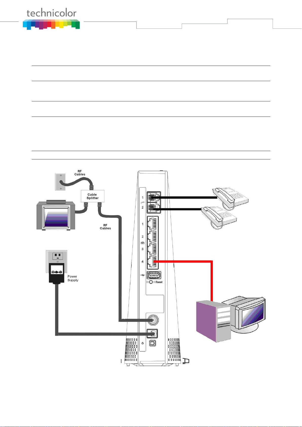
Installation procedure for connecting to the Ethernet interface
Follow these steps for proper installation.
Plug the coaxial cable to the cable wall outlet and the other end to the modem’s cable connector.
Note: To ensure a fast registration of the modem, the coaxial cable must be connected to
the modem before it is powered on.
Plug the power supply into the socket of the cable modem and two-pin plug in the AC outlet then press
the Power Switch, power on the modem.
Note: Only use the power supply that comes with the modem. Using another power supply
can cause damage to the product, and will void the warranty.
Connect an Ethernet cable (direct connection, see below) to the Ethernet port at the back of the computer,
and the other end to the ETHERNET port on the rear panel of the cable modem. The modem will seek the
appropriate cable signal on the cable television network and go through the initial registration process on
its own. The modem is ready for data transfer after the green LED "ONLINE" is lit continuously.
Note: the button "reset" at the back of the modem is used primarily for maintenance.
Fig. 1-7 Connect to the Modem

Page 19 / 91
Telephone or Fax Connection
When properly connected, most telephony devices can be used with the Wireless Voice Gateway just as
with a conventional telephone service. To make a normal telephone call, pick up the handset; listen for a
dial tone, then dial the desired number. For services such as call waiting, use the hook switch (or FLASH
button) to change calls. The following procedures describe some of the possible connection schemes for
using telephony devices with the Wireless Voice Gateway.
1. Connect a standard phone line cord directly from the phone (fax machine, answering machine, caller
ID box, etc.) to one of the LINE jacks on the Wireless Voice Gateway.
2. If there is a phone line in your home which is NOT connected to another telephone service provider,
connect a standard phone line cord from a jack on this line to one of the LINE jacks of the Wireless
Voice Gateway. Connect a standard phone line cord directly from the phone (fax machine, answering
machine, caller ID box, etc.) to one of the other jacks in the house that uses that line.
3. If you have a multi-line telephone, connect a standard phone line cord (not an RJ-14 type line cord)
from the phone to the LINE jacks on the Wireless Voice Gateway. (Other phones can be added to
each line by using standard phone line splitters.)
Page 20 / 91
CHAPTER 2: WEB CONFIGURATION
To make sure that you can access the Internet successfully, please check the following first.
1. Make sure the connection (through Ethernet) between the Wireless Voice Gateway and your
computer is OK.
2. Make sure the TCP/IP protocol is set properly.
3. Subscribe to a Cable Company.
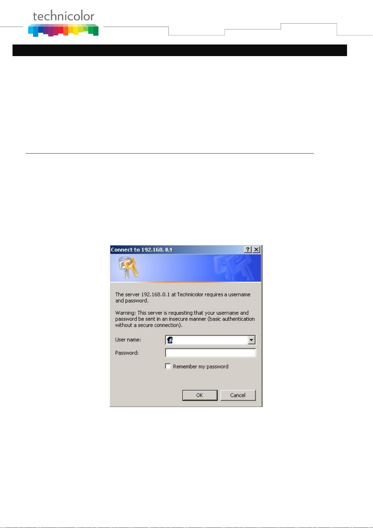
Accessing the Web Configuration
The Wireless Voice Gateway offers local management capability through a built-in HTTP server and a
number of diagnostic and configuration web pages. You can configure the settings on the web page and
apply them to the device.
Once your host PC is properly configured; please proceed as follows:
1. Start your web browser and type the private IP address of the Wireless Voice Gateway on
the URL field: 192.168.0.1
2. After connecting to the device, you will be prompted to enter username and password. By
default, the username is “ ” (empty) and the password is “admin”.
Fig2-1 Login dialogue
If you login successfully, the main page will appear.
Page 21 / 91
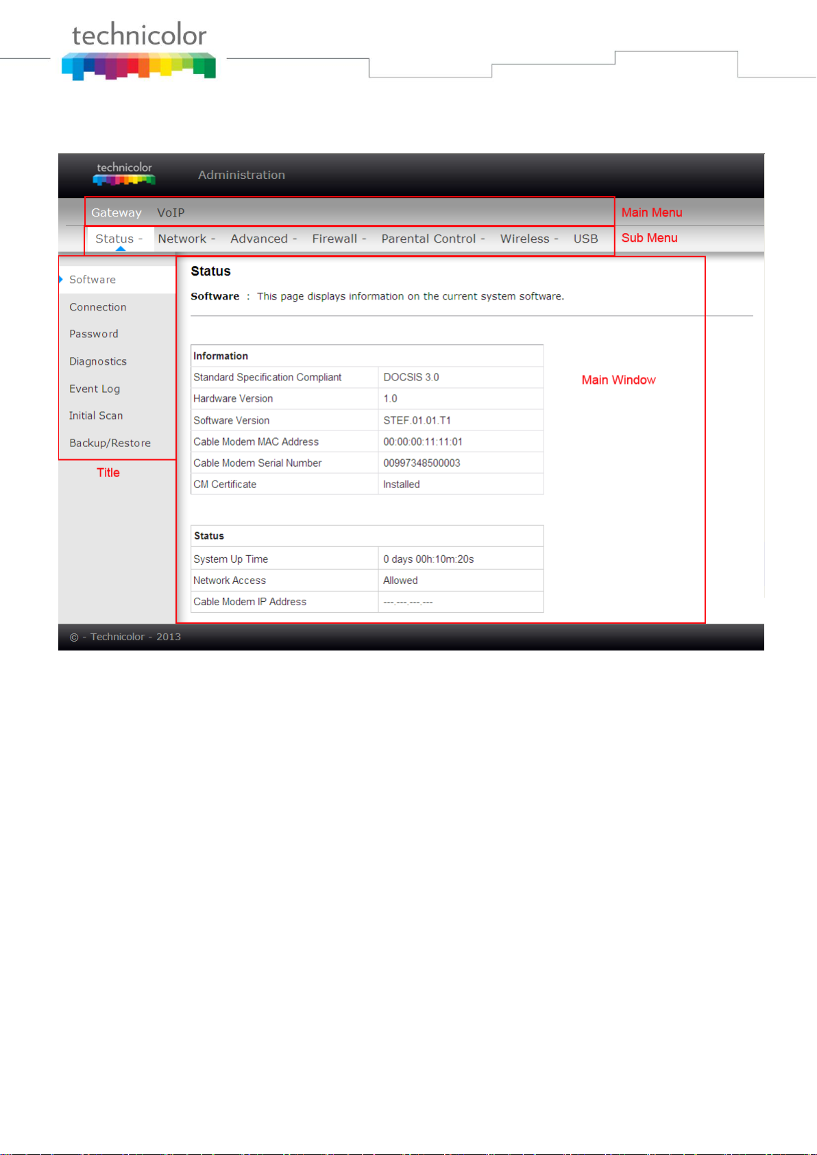
Outline of Web Manager
The main screen will be shown as below.
Fig. 2-2 Outline of Web Manager
Main Menu: the hyperlinks on the top of the page, including Gateway, VoIP and several sub-menu
items
Sub Menu: under the main menu, sub menu use to enter each function, e.g., Status, Network,
Firewall…
Title: the sidebar on the left side of the page indicates the title of this management interface, e.g.,
Software in this example
Main Window: the current workspace of the web management, containing configuration or status
information
For easy navigation, the pages are organized in groups with group in names main menu. Individual page
names within each group are provided in the sub menu and sidebar. So to navigate to a page, click the
group hyperlink at the top, then the sub menu for the function, finally choose the title on the sidebar.
Your cable company may not support the reporting of some items of information listed on your gateway’s
internal web pages. In such cases, the information field appears blank. This is normal.
Page 22 / 91
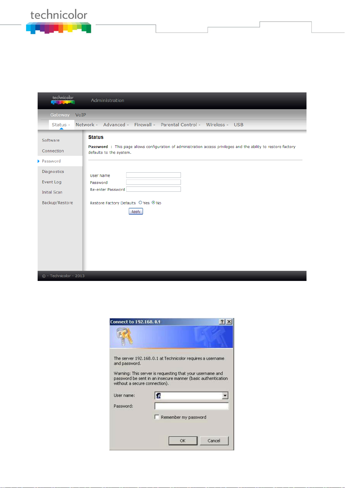
Warning message to change the password
At your first connection or while the password is the default one, a warning message is displayed on the
top banner of each Web configuration page. We want to encourage you to change the password in order
to enforce the security of your modem. Please refer to the chapter password page 25 for more
information.
Fig. 2-3 Gateway\Status\Password
To change the password: type the password, and re-enter it again.
If the password is accepted, you are required to re log on the web pages:
Fig. 2-4 Password request dialog
Page 23 / 91
Gateway – Status Web Page Group
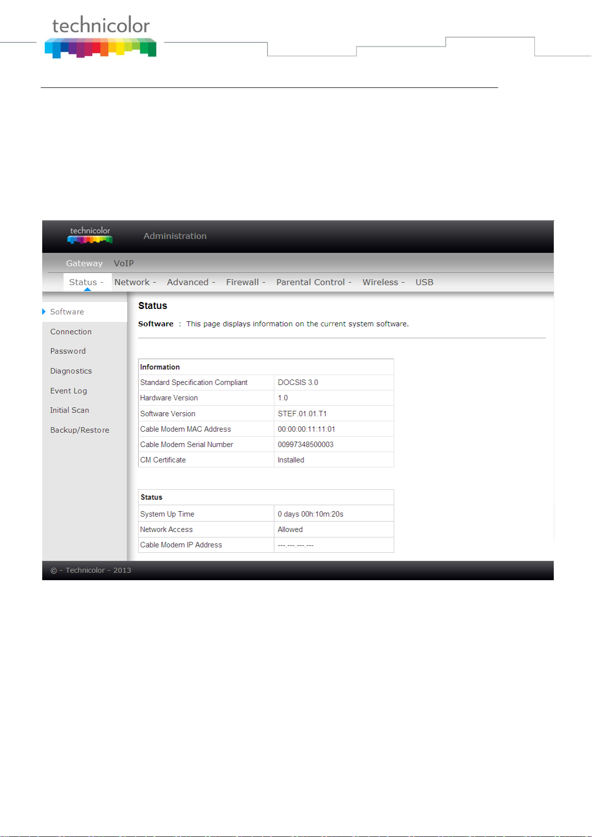
1. Software
The information section shows the hardware and software information about your gateway.
The status section of this page shows how long your gateway has operated since last time being powered
up, and some key information the Cable Modem received during the initialization process with your cable
company. If Network Access shows “Allowed,” then your cable company has configured your gateway to
have Internet connectivity. If not, you may not have Internet access, and should contact your cable
company to resolve this.
Fig.2-5 Gateway\Status\Software
Page 24 / 91
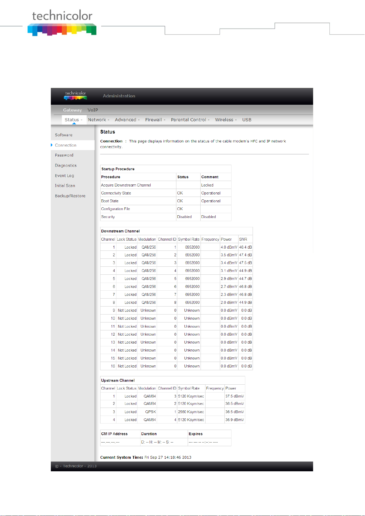
2. Connection
This page reports current connection status containing startup procedures, downstream and upstream
status, CM online information, and so on. The information can be useful to your cable company’s support
technician if you’re having problems.
Fig. 2-6 Gateway\Status\Connection
Page 25 / 91
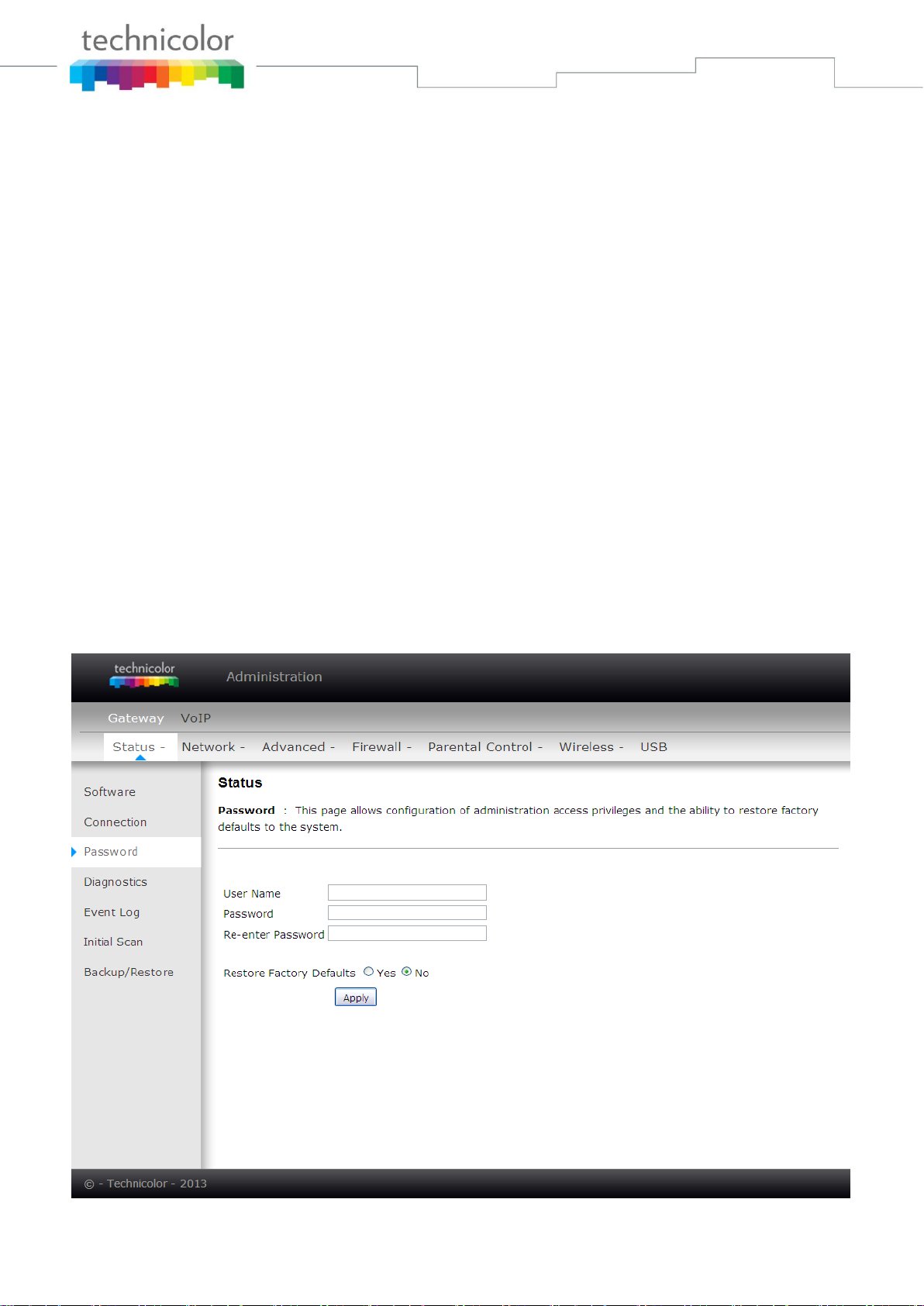
3. Password
By default, the username is empty (“”) and the password is “admin”.
This is set by different actions (non exhaustive list):
- at the manufactory level,
- following a reset factory on the modem,
- following a reset from the operator,
- following a change by the user who wants to come back to the default setting after using its own
settings
When the current password is the default one, the user is strongly encouraged to change the default web
password.
At your first connection or while the password is the default one, a warning message is displayed on the
top banner of each Web configuration page. We want to encourage you to change the password in order
to enforce the security of your modem.
The password can be a maximum of 8 characters and is case sensitive. In addition, this page can be used
to restore the gateway to its original factory settings. Use this with caution, as all the settings you have
made will be lost. To perform this reset, set Restore Factory Defaults to Yes and click Apply. This has
the same effect as a factory reset using the rear panel reset switch, where you hold on the switch for 5
seconds, then release it.
Note: We are always suggesting you to modify the password. This is a basic protection against wrongful
access to the Gateway Web pages.
Fig. 2-7 Gateway\Status\Password
Page 26 / 91
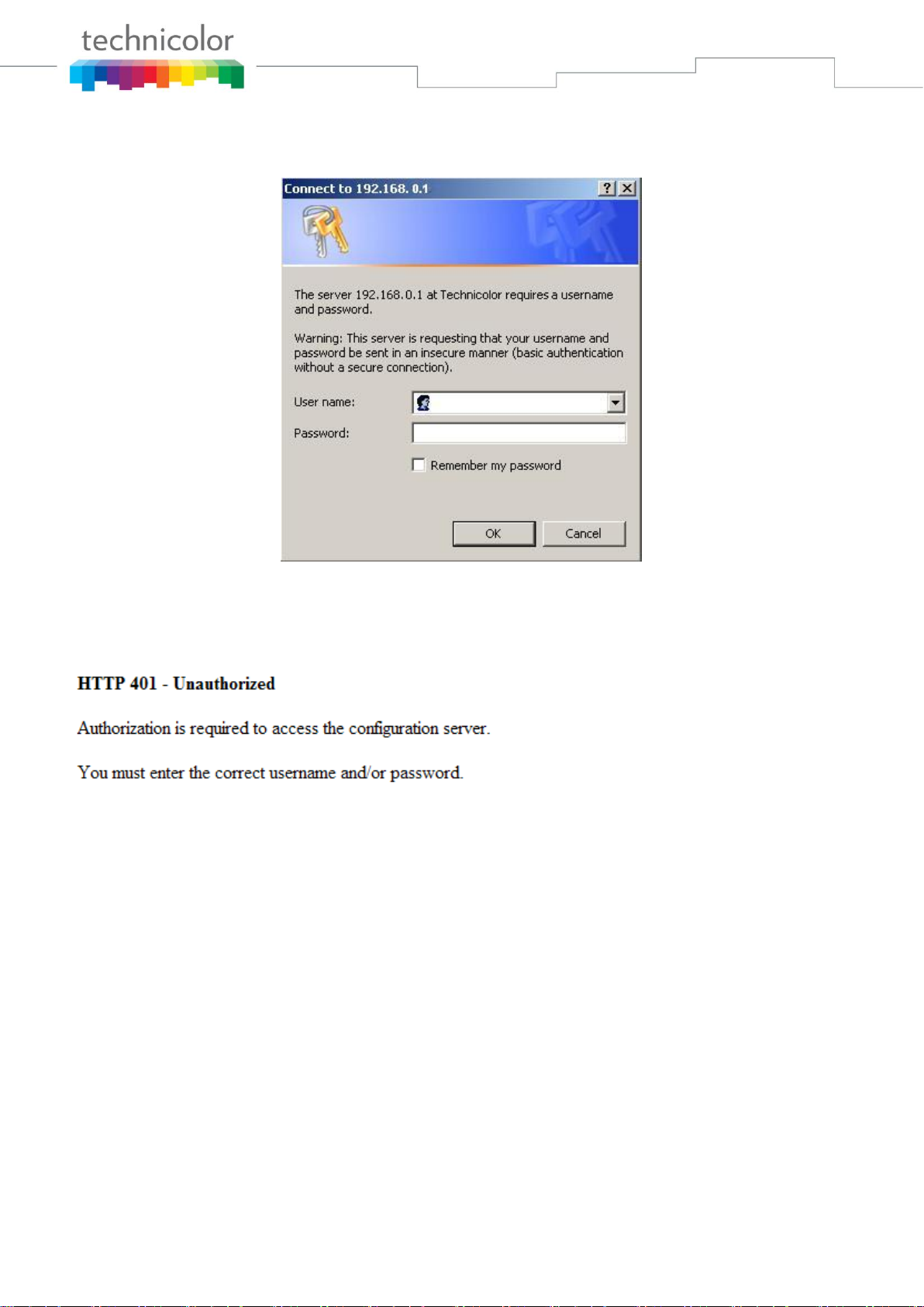
To change the password: type the password, and re-enter it again.
If the password is accepted, you are required to re log on the web pages:
Fig. 2-8 Password request dialog
If the password is no accepted, an error message is displayed:
Please reflash the web and wait for Password dialog pop-up, then typing the correct username and
password again.
Page 27 / 91
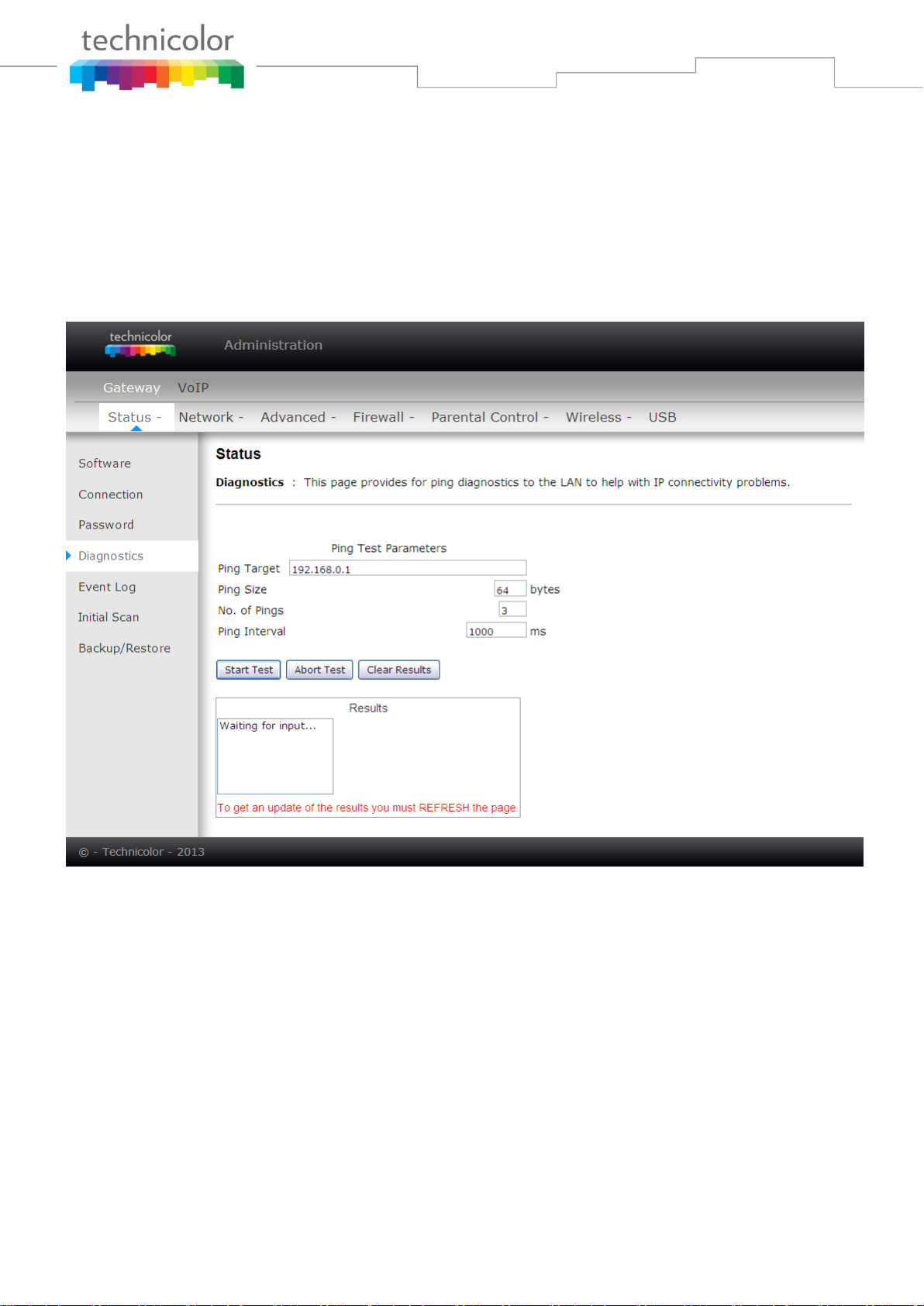
4. Diagnostics
This page offers basic diagnostic tools for you to use when connectivity problems occur. When you ping
an Internet device, you send a packet to its TCP/IP stack, and it sends one back to yours. To use the ping
Test, enter the information needed and press Start Test; the Result will be displayed in the lower part of
the window. Press Abort Test to stop, and Clear Results to clear the result contents. Note: Firewalls may
cause pings to fail but still provide you TCP/IP access to selected devices behind them. Keep this in mind
when ping a device that may be behind a firewall. Ping is most useful to verify connectivity with PCs
which do not have firewalls, such as the PCs on your LAN side.
Fig. 2-9 Gateway\Status\Diagnostics
Page 28 / 91
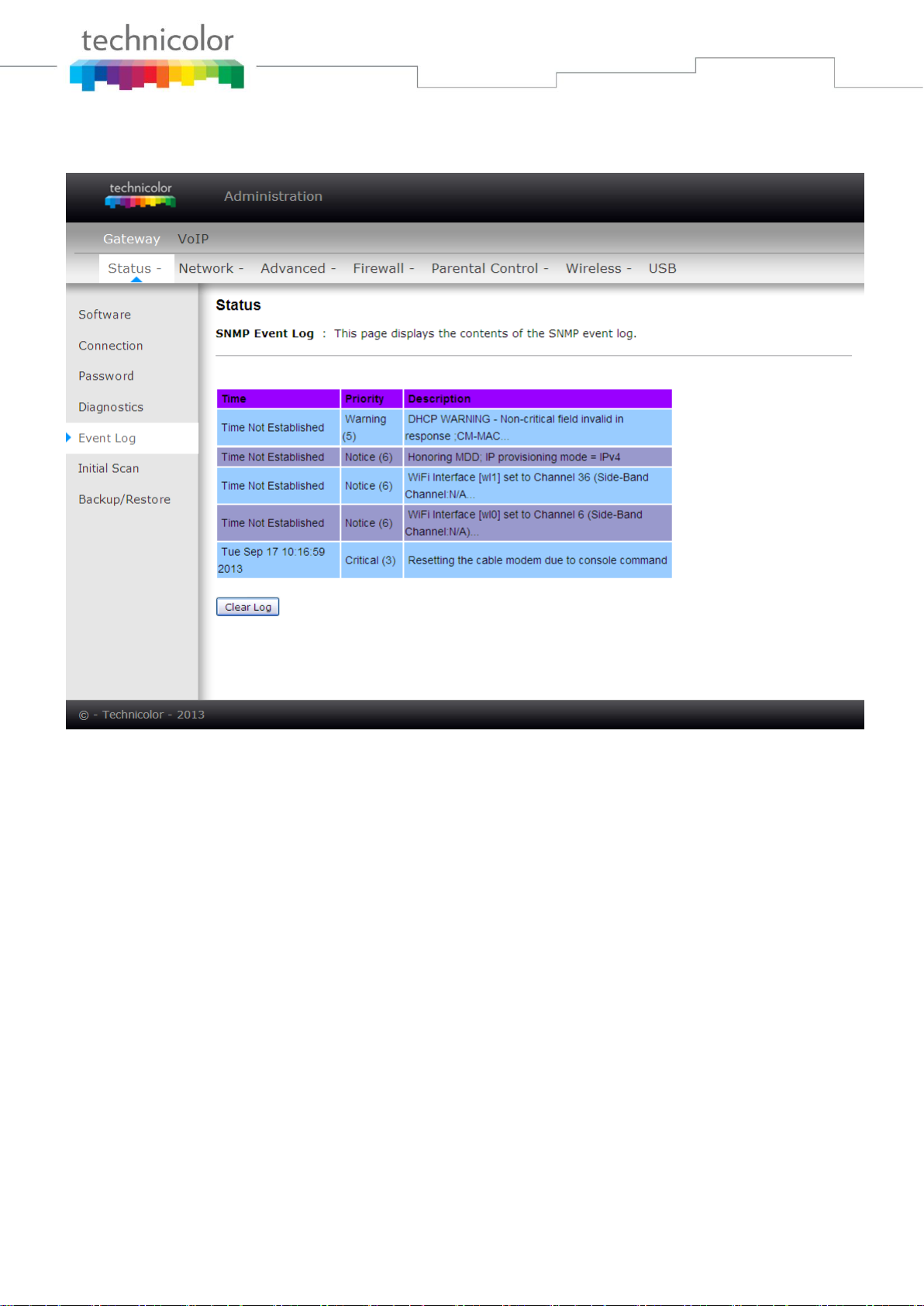
5. Event Log
This page displays the contents of the SNMP event log. Press “Clear Log” button to clear the logs.
Fig. 2-10 Gateway\Status\Event Log
 Loading...