


TC7200.U User Manual release note
Date |
Author |
Version |
Description |
|
|
|
|
2012/05/10 |
Wayne Hsieh |
1.0 |
First release, |
|
|
|
This UM refer PDS: |
|
|
|
PDS_PKE1331-D49(EU-UPC-ROHS)_TC7200.U_V.0.2_20120423.docx |
|
|
|
|
2012-06-14 |
Wayne Hsieh, |
1.1 |
Modified the inappropriate part what Morgane reminded. |
|
Lilian Li |
|
|
|
|
|
|
2012-08-07 |
Agustin |
1.2 |
Replace with UPC WEB UI |
|
|
|
|
2012-08-17 |
Agustin |
1.3 |
Replace with UPC WEB UI |
|
|
|
|
Page 1 / 84
CAUTION
Disconnect power before servicing.
This device is intended for indoor operation only. Telephone jacks Line 1 and Line 2 must not be connected to outside wiring.
CAUTION
To ensure reliable operation and to prevent overheating, provide adequate ventilation for this modem and keep it away from heat sources. Do not locate near heat registers or other heat-producing equipment. Provide for free air flow around the Wireless Voice Gateway and its power supply.
This symbol on the product ensures that the device complies with European legislation, Directive 89/336/EEC, 73/23/EEC, 93/68/EEC, which covers the EMC (electromagnetic compatibility), and safety aspects of marking.
This symbol means that your inoperative electronic appliance must be collected separately and not mixed with the household waste. The European Union has implemented a specific collection and recycling system for which producers' are responsible.
This appliance has been designed and manufactured with high quality materials and components that can be recycled and reused. Electrical and electronic appliances are liable to contain parts that are necessary in order for the system to work properly but which can become a health and environmental hazard if they are not handled or disposed of in the proper way. Consequently, please do not throw out your inoperative appliance with the household waste.
If you are the owner of the appliance, you must deposit it at the appropriate local collection point or leave it with the vendor when buying a new appliance.
-If you are a professional user, please follow your supplier's instructions.
-If the appliance is rented to you or left in your care, please contact your service provider. Help us protect the environment in which we live!
Page 2 / 84

NORTH AMERICAN CABLE INSTALLER:
This reminder is provided to call your attention to Article 820-40 of the National Electrical Code (Section 54 of the Canadian Electrical Code, Part 1) which provides guidelines for proper grounding and, in particular, specifies that the cable ground shall be connected to the grounding system of the building as close to the point of cable entry as practical.
Operating Information |
|
|
Operating Temperature: |
0˚ - 40˚ C |
(32˚ - 104˚ F) |
Storage Temperature: |
-20˚ to 70˚ C |
(-4˚ – 157˚ F) |
If you purchased this product at a retail outlet, please read the following:
Product Information
Keep your sales receipt to obtain warranty parts and service and for proof of purchase. Attach it here and record the serial and model numbers in case you need them. The numbers are located on the back of the product.
Model No. ____________________________Serial No ________________________________
Purchase Date: ________________________Dealer/Address/Phone: _________________________
Page 3 / 84

Safety Recommendations
REMEMBER SAFETY FIRST
Using equipment safely
Your Cable Modem has been manufactured to meet safety standards, but you must take care if you want it to perform properly and safely.
It is important that you read this booklet completely, especially the safety instructions below. If you have any doubts about the installation, operation or safety of decoder, please contact your supplier.
To avoid the risk of electric shock
Disconnect the Cable Modem from the mains supply before you connect the Cable Modem to (or disconnect it from) any other equipment. Remember that contact with 110 ~ 240 Volt AC mains can be lethal or cause severe electric shock.
Never remove the Cable Modem’s cover. Should the Cable Modem fail, contact the Customer Service to arrange repair or service.
Never allow anyone to push anything into holes, slots or any other opening in the case
Do not block the Cable Modem’s ventilation slots; never stand it on soft furnishings or carpets
Do not put anything on the Cable Modem which might spill or drip into it (eg. Lighted candles or containers of liquids). Do not expose the Cable Modem to dripping or splashing. If an object or liquid enters inside the Cable Modem, unplug it immediately and contact the Customer Service.
Do not store the Cable Modem in excessively hot, cold or damp conditions. The Cable Modem is intended to operate at an ambient temperature of less than 40 degrees Celsius and a maximum humidity level of 75%. In case of a storm, it is recommended that you unplug the Cable Modem from the mains and from the R/F Network.
Leave the mains socket accessible so that you can unplug the set quickly
Connecting to the mains supply
This Cable Modem is designed to operate at 110 ~ 240 VAC.
If you are in any doubt about the mains lead, the plug or connection, please consult the Customer Service.
Only the power adapter supplied with the decoder has to be used
Ensuring optimum performance
Leave 7cm to 10cm around the Cable Modem to ensure that proper ventilation gets to the Cable Modem.
Do not store your Cable Modem on its side (if not allowed)
To clean the Cable Modem, use a dry, clean soft cloth with no cleaning solvent or abrasive products. Clean the ventilation openings regularly.
Page 4 / 84

MAIN TECHNICALSPECIFICATIONS
General
Operating voltage |
100 ~ 240 VAC |
|
|
Typical Power consumption |
18 W max |
|
|
Dimensions (W x H x D) |
220mm x 166.7mm x 43mm |
|
|
Operating temperature range |
0 – 40 °C |
|
|
Storage temperature range |
-20 – 70 °C |
|
|
AC adapter (or plug-in adapter) |
ADAPTER 18W 12VDC/1.5A |
type |
|
|
|
Connections
DC input |
12V/ 1.5A |
|
|
Cable input |
1xCoaxial cable connector |
|
|
USB input |
1x 2.0 USB connector |
|
|
Phone plugs |
2xRJ11 |
|
|
Ethernet plugs |
4xRJ-45 |
|
|
This symbol on your set guarantees that your product complies with the European Directives 1999/5/ECand 2009/125/EC on Safety, Telecom, Electromagnetic Compatibility and Energy related Products.
Page 5 / 84

Chapter 1: Connections and Setup .......................................................................................... |
9 |
|
Turning on the Wireless Voice Gateway................................................................................ |
9 |
|
Introduction ........................................................................................................................ |
9 |
|
Wireless Voice Gateway Features ...................................................................................... |
9 |
|
What’s on the CD-ROM .................................................................................................. |
10 |
|
Computer Requirements................................................................................................. |
10 |
|
Wireless Voice Gateway Overview....................................................................................... |
10 |
|
Front Panel..................................................................................................................... |
10 |
|
Rear Panel ...................................................................................................................... |
13 |
|
Wall Mounting ................................................................................................................ |
14 |
|
Relationship among the Devices ........................................................................................ |
15 |
|
What the Modem Does ................................................................................................... |
15 |
|
What the Modem Needs to Do Its Job.............................................................................. |
15 |
|
Contact Your Local Cable Company ................................................................................ |
16 |
|
Connecting the Wireless Voice Gateway to a Single Computer............................................ |
16 |
|
Attaching the Cable TV Wire to the Wireless Voice Gateway ............................................ |
17 |
|
Installation procedure for connecting to the Ethernet interface....................................... |
18 |
|
Telephone or Fax Connection......................................................................................... |
19 |
|
Chapter 2: WEB Configuration ............................................................................................... |
20 |
|
Accessing the Web Configuration ...................................................................................... |
20 |
|
Outline of Web Manager ................................................................................................. |
22 |
|
Status – Status Web Page Group......................................................................................... |
23 |
|
1. |
System ...................................................................................................................... |
23 |
2. |
Connection/Basic ...................................................................................................... |
24 |
3. |
Connection/Upstream ............................................................................................... |
25 |
4. |
Connection/Downstream........................................................................................... |
26 |
5. |
MTA/Status ............................................................................................................... |
27 |
6. |
Diagnostics/Ping....................................................................................................... |
28 |
7. |
Diagnostics/Trace Route ........................................................................................... |
29 |
Basic – Basic Web Page Group ............................................................................................ |
30 |
|
1. |
Internet ..................................................................................................................... |
30 |
2. |
Local Area Network ................................................................................................... |
31 |
|
|
Page 6 / 84 |

3. |
DHCP Client Devices.................................................................................................. |
32 |
Advanced – Advanced Web Page Group.............................................................................. |
33 |
|
1. |
Options ..................................................................................................................... |
33 |
2. |
IP Filters .................................................................................................................... |
34 |
3. |
MAC Filters................................................................................................................ |
35 |
4. |
Port Filters ................................................................................................................ |
36 |
5. |
Forwarding................................................................................................................ |
37 |
6. |
Port Triggers ............................................................................................................. |
38 |
7. |
DMZ Host .................................................................................................................. |
39 |
8. |
Firewall ..................................................................................................................... |
40 |
Parental Control – Parental Control Web Page Group .......................................................... |
41 |
|
1. |
Device Rules.............................................................................................................. |
41 |
2. |
Basic Setup................................................................................................................ |
43 |
3. |
WEB Site Filters.......................................................................................................... |
44 |
4. |
TOD Filters................................................................................................................ |
46 |
Wireless – Wireless Web Page Group .................................................................................. |
48 |
|
1. |
2.4 GHz\Radio .......................................................................................................... |
49 |
2. |
2.4 GHz\Security....................................................................................................... |
50 |
3. |
2.4 GHz\Advanced .................................................................................................... |
51 |
4. |
2.4 GHz\Access Control ............................................................................................ |
53 |
5. |
2.4 GHz\WPS............................................................................................................. |
54 |
6. |
5 GHz\Radio ............................................................................................................. |
55 |
7. |
5 GHz\Security.......................................................................................................... |
56 |
8. |
5 GHz\Advanced ....................................................................................................... |
57 |
9. |
5 GHz\Access Control ............................................................................................... |
59 |
10. 5 GHz\WPS.............................................................................................................. |
60 |
|
USB – USB Web Page Group ................................................................................................ |
61 |
|
1. |
USB Basic................................................................................................................... |
61 |
2. |
Approuved Devices.................................................................................................... |
62 |
3. |
Storage Basic............................................................................................................. |
63 |
4. |
Storage Advanced ..................................................................................................... |
64 |
|
|
Page 7 / 84 |

5. |
MEDIA SERVER........................................................................................................... |
65 |
System – System Web Page Group...................................................................................... |
68 |
|
1. |
Password................................................................................................................... |
68 |
2. |
Backup and Recovery\Backup .................................................................................... |
69 |
3. |
Backup and Recovery\Restore ................................................................................... |
70 |
4. |
Backup and Recovery\Factory Default........................................................................ |
71 |
5. |
Log\Syslog ................................................................................................................ |
72 |
6. |
Log\Local Log ........................................................................................................... |
73 |
Chapter 3: Networking .......................................................................................................... |
74 |
|
Communications ............................................................................................................... |
74 |
|
Type of Communication .................................................................................................... |
74 |
|
Cable Modem (CM) Section ................................................................................................ |
75 |
|
Networking Section ........................................................................................................... |
75 |
|
Three Networking Modes................................................................................................... |
75 |
|
Cable Modem (CM) Mode................................................................................................... |
76 |
|
Residential Gateway (RG) Mode.......................................................................................... |
77 |
|
Chapter 4: Additional Information ......................................................................................... |
79 |
|
Frequently Asked Questions .............................................................................................. |
79 |
|
General Troubleshooting ................................................................................................... |
81 |
|
Service Information ........................................................................................................... |
82 |
|
Glossary ............................................................................................................................ |
83 |
|
Page 8 / 84

CHAPTER 1: CONNECTIONS AND SETUP
Turning on the Wireless Voice Gateway
After installing the Wireless Voice Gateway and turn it on for the first time (and each time the modem is reconnected to the power), it goes through several steps before it can be used. Each of these steps is represented by a different pattern of flashing lights on the front of the modem.
If there is no lighted LEDs on the front panel, check the power adapter plug-in the power jack and connect to CM correctly.
Note: All indicators flash once before the initialization sequence.
If both DS and US LEDs are flashing, it means the Wireless Voice Gateway is automatically updating its system software. Please wait for the lights to stop flashing. Do not remove the power supply or reset the Wireless Voice Gateway during this process.
Introduction
Wireless Voice Gateway Features
Full Band Capture Front End
Lowers Power with Advanced Power Management
Advanced Processor architecture.
Cable Europe Labs Euro-DOCSIS 1.0/1.1/2.0/3.0 Standard certified.
Euro-PacketCable 1.0/1.5 Standard certified.
Support Multiple Provisioning mode.
Standard RJ-45 connector for 10/100/1000BaseT Ethernet with auto-negotiation and MDIX functions.
RJ-11 Foreign Exchange Station (FXS) port for IP telephony.
Support simultaneous voice and data communications.
Echo Cancellation.
Voice Active Detection (VAD).
DTMF detection and generation.
Comfort Noise Generation (CNG).
Support V.90 fax and modem services.
SNMP network management support.
802.11a/b/g/n are supported, 20/40 MHz bandwidth.
Support Web pages and private DHCP server for status monitoring.
Page 9 / 84

What’s on the CD-ROM
Insert the Wireless Voice Gateway CD-ROM into your CD-ROM drive to view troubleshooting tips, the internal diagnostics, and other valuable information.
CD-ROM Contents:
Electronic copy of this user’s guide in additional languages (PDF format)
Adobe Acrobat Reader — application you can load to read PDF format, if you don’t have it loaded already
Links to Technicolor web site
Euro-DOCSIS and Euro-PacketCable are trademarks of Cable Television Laboratories, Inc.
Computer Requirements
For the best possible performance from your Wireless Voice Gateway, your personal computer must meet the following minimum system requirements (note that the minimum requirements may vary by cable companies):
|
IBM PC COMPATIBLE |
MACINTOSH** |
|
|
|
CPU |
Pentium preferred |
PowerPC or higher |
|
|
|
System RAM |
16MB (32MB preferred) |
24MB (32MB preferred) |
|
|
|
Operating System |
Windows* NT / 2000 / Me / XP / |
Mac OS** 7.6.1 or higher |
|
Vista / Windows 7, Linux |
|
|
|
|
Video |
VGA or better (SVGA preferred) |
VGA or better (SVGA built-in preferred) |
|
|
|
CD-ROM Drive |
Required |
Required |
|
|
|
Ethernet |
10BaseT , 100BaseT or 1000BaseT |
10BaseT , 100BaseT or 1000BaseT |
|
An Ethernet card makes it possible for your computer to pass data to and from |
|
|
the internet. You must have an Ethernet card and software drivers installed in |
|
|
your computer. You will also need a standard Ethernet cable to connect the |
|
|
Ethernet card to your Wireless Voice Gateway. |
|
Software |
A TCP/IP network protocol for each machine |
|
Microsoft Internet Explorer 4.0 or later or |
|
Netscape Navigator 4.0 or later. |
*Windows is a trademark of Microsoft Corporation.
**Macintosh and the Mac OS are trademarks of Apple Computer, Inc.
Wireless Voice Gateway Overview
Front Panel
Page 10 / 84
Fig. 1-1 Front Panel
The following illustration shows the front panel:
Power - Indicates the Power status.
DS - Indicates the status of Data reception by the cable modem from the Network (Downstream Traffic).
US - Indicates the status of Data transmission by the cable modem to the Network (Upstream Traffic).
Online - Displays the status of your cable connection. The light is off when no cable connection is detected and fully lit when the modem has established a connection with the network and data can be transferred.
Eth. - Indicates the state of Ethernet ports.
Wireless - Indicates the traffic on the wireless network.
Tel - Indicates the status of the telephone Phone 1 and Phone 2.
Page 11 / 84

The lights on the front panel LEDs are described in the table below (from left to right):
ON = the LED is light, OFF = the LED is gray, FLASH = the LED is blinking.
TC7200.U |
|
Power |
|
Internet |
|
Eth. |
|
Wireless |
|
Phone 1 |
|
Phone 2 |
|
Description |
|
||
|
|
|
|
|
|
|
|
||||||||||
|
|
|
|
|
|
|
|
||||||||||
|
|
|
|
|
|
|
|
|
|
|
|||||||
|
|
|
|
DS |
US |
|
Online |
|
|
|
|
|
|
|
|
|
|
|
|
|
|
|
|
|
|
|
|
|
|
|
|
||||
|
|
|
|
|
|
|
|
|
|
|
|
|
|
|
|
|
|
|
|
ON |
ON |
ON |
|
ON |
ON |
X |
ON |
ON |
Power on 0.25 sec |
||||||
|
|
|
|
|
|
|
|
||||||||||
|
|
ON |
0.25 second |
||||||||||||||
|
|
|
|
|
|
|
|
|
|
|
|
||||||
Boot-up |
|
|
|
|
|
|
|
|
|
|
|
|
|
|
|
|
|
|
ON |
FLASH |
FLASH |
|
FLASH |
X |
X |
X |
X |
From power ON to system initialization |
|||||||
Operation |
|
|
complete |
||||||||||||||
|
|
|
|
|
|
|
|
|
|
|
|
|
|
|
|||
|
|
|
|
|
|
|
|
|
|
|
|
|
|
|
|
|
|
|
|
ON |
ON |
ON |
|
ON |
X |
X |
X |
X |
Following system initialization |
||||||
|
|
||||||||||||||||
|
|
|
|
|
|
||||||||||||
|
|
|
|
|
|
complete to (before) DS scanning |
|||||||||||
|
|
|
1 second |
||||||||||||||
|
|
|
|
|
|
|
|
|
|
|
|
|
|||||
|
|
|
|
|
|
|
|
|
|
|
|
|
|
|
|||
|
|
|
|
|
|
|
|
|
|
|
|
||||||
|
|
ON |
FLASH |
OFF |
|
OFF |
X |
X |
X |
X |
During DS scanning and acquiring SYNC |
||||||
|
|
|
|
|
|
|
|
|
|
|
|
|
|
|
|
|
|
|
|
ON |
ON |
FLASH |
|
OFF |
X |
X |
X |
X |
From SYNC completed, receiving UCD |
||||||
|
|
|
to ranging completed |
||||||||||||||
|
|
|
|
|
|
|
|
|
|
|
|
|
|
|
|
||
|
|
|
|
|
|
|
|
|
|
|
|
|
|
|
|
|
|
|
|
|
|
|
|
|
|
|
|
|
|
|
|
|
|
During DHCP, configuration file |
|
DOCSIS |
|
|
|
|
|
|
|
|
|
|
|
|
|
|
|
download, registration, and Baseline |
|
|
|
|
|
|
|
|
|
|
|
|
|
|
|
|
Privacy initialization: |
||
Start-up |
|
|
|
|
|
|
|
|
|
|
|
|
|
|
|
||
|
ON |
ON |
ON |
|
FLASH |
X |
X |
X |
X |
DHCP status: 1 second ON and 1 |
|||||||
Operation |
|
|
|||||||||||||||
|
|
|
|
|
|
|
|
|
|
|
|
|
|
|
second OFF, |
||
|
|
|
|
|
|
|
|
|
|
|
|
|
|
|
|
||
|
|
|
|
|
|
|
|
|
|
|
|
|
|
|
|
TFTP status: 0.25 second ON and 0.25 |
|
|
|
|
|
|
|
|
|
|
|
|
|
|
|
|
|
second OFF |
|
|
|
|
|
|
|
|
|
|
|
|
|
||||||
|
|
ON |
ON |
ON |
|
ON |
X |
X |
X |
X |
Operational (NACO=ON) |
||||||
|
|
|
|
|
|
|
|
|
|
|
|
||||||
|
|
ON |
FLASH |
FLASH |
|
OFF |
X |
X |
X |
X |
Operational (NACO=OFF) |
||||||
|
|
|
|
|
|
|
|
|
|
|
|
|
|
|
|
|
|
|
|
|
|
|
|
|
|
|
|
|
|
|
|
|
|
Wait registration with all DS and all US |
|
|
|
FLASH |
FLASH |
FLASH |
|
FLASH |
FLASH |
X |
X |
X |
– Lights Flash sequentially from the |
||||||
|
|
|
right to left Minimum duration 3 |
||||||||||||||
|
|
|
|
|
|
|
|
|
|
|
|
|
|
|
|
||
|
|
|
|
|
|
|
|
|
|
|
|
|
|
|
|
seconds |
|
|
|
|
|
|
|
|
|
|
|
|
|
|
|
|
|
|
|
|
|
|
|
|
|
|
|
|
|
|
|
|
|
|
|
From 1 to 4 DS, from 1 to 4 LEDs are |
|
|
|
|
|
|
|
|
|
|
|
|
|
|
|
|
|
ON |
|
Channel |
|
X |
X |
X |
|
X |
OFF |
X |
X |
X |
From 5 to 8 DS, From 1 to 4 LEDs are |
||||||
|
|
||||||||||||||||
|
|
|
|||||||||||||||
Bonding |
|
|
|
|
|
|
|
|
|
|
|
|
|
|
|
flashing |
|
|
|
|
|
|
|
|
|
|
|
|
|
|
|
|
|
|
|
Operation |
|
|
|
|
|
|
|
|
|
|
|
|
|
|
|
Duration 3 seconds |
|
|
|
|
|
|
|
|
|
|
|
|
|
|
|
|
|
|
|
|
|
OFF |
X |
X |
|
X |
X |
X |
X |
X |
From 1 to 4 US, from 1 to 4 LEDs are |
||||||
|
|
|
ON. |
||||||||||||||
|
|
|
|
|
|
|
|
|
|
|
|
|
|
|
|
||
|
|
|
|
|
|
|
|
|
|
|
|
|
|
|
|
|
|
|
|
|
|
|
|
|
|
|
|
|
|
|
|
|
|
Wait registration with all DS and all US |
|
|
|
FLASH |
FLASH |
FLASH |
|
FLASH |
FLASH |
X |
X |
X |
– Lights Flash sequentially from the left |
||||||
|
|
|
|
|
|
|
|
|
|
|
|
|
|
|
|
to right |
|
|
|
|
|
|
|
|
|
|
|
|
|
||||||
|
|
ON |
ON |
ON |
|
ON |
X |
X |
FLASH |
OFF |
MTA DHCP |
||||||
MTA |
|
|
|
|
|
|
|
|
|
|
|
|
|
|
|
|
|
|
ON |
ON |
ON |
|
ON |
X |
X |
OFF |
FLASH |
MTA SNMP/TFTP |
|||||||
initialization |
|
|
|||||||||||||||
|
|
|
|
|
|
|
|
|
|
|
|
|
|
|
|
|
|
|
|
ON |
ON |
ON |
|
ON |
X |
X |
ON |
ON |
RSIP for NCS/Register for SIP |
||||||
|
|
|
|
|
|
|
|
|
|
|
|
|
|
|
|||
CPE |
|
|
|
|
|
|
|
OFF |
OFF |
|
|
|
|
No Ethernet / Wireless Link |
|||
|
ON |
X |
X |
|
X |
ON |
ON |
X |
X |
Ethernet / Wireless Link |
|||||||
Operation |
|
|
|||||||||||||||
|
|
|
|
|
|
|
FLASH |
FLASH |
|
|
|
|
TX/RX Ethernet / Wireless Traffic |
||||
|
|
|
|
|
|
|
|
|
|
|
|
||||||
|
|
|
|
|
|
|
|
|
|
|
|
|
|
|
|
|
|
|
|
ON |
|
|
|
|
|
|
|
|
ON |
ON |
Both Lines On-Hook |
||||
|
|
|
|
|
|
|
|
|
|
|
|
|
|
||||
MTA |
|
ON |
|
<CM Normal Operation> |
FLASH |
ON |
Tel1 Off-hook, Tel2 On-hook |
||||||||||
|
|
|
|
|
|
|
|
|
|
||||||||
Operation |
|
|
|
|
|
|
|
|
|
|
|||||||
|
ON |
|
ON |
FLASH |
Tel1 On-hook, Tel2 Off-hook |
||||||||||||
|
|
|
|
|
|
|
|
|
|||||||||
|
|
|
|
|
|
|
|
|
|
||||||||
|
|
|
|
|
|
|
|
|
|
|
|
|
|
||||
|
|
ON |
|
|
|
|
|
|
|
|
FLASH |
FLASH |
Both Lines Off-Hook |
||||
|
|
|
|
|
|
|
|
|
|
|
|
|
|
|
|
|
|
Page 12 / 84
SW |
|
|
|
|
|
|
|
|
|
|
A software download and while |
Download |
ON |
FLASH |
FLASH |
ON |
X |
|
X |
X |
|
X |
|
|
|
updating the FLASH memory |
|||||||||
Operation |
|
|
|
|
|
|
|
|
|
|
|
|
|
|
|
|
|
|
|
|
|
|
|
|
|
|
|
|
|
|
|
|
|
|
|
|
|
|
|
|
|
Table 1-1 LED behavior |
|
|
|||
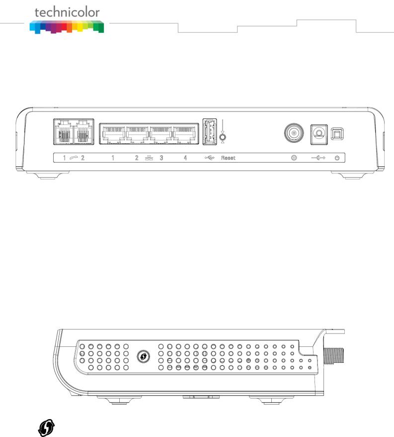
Rear Panel |
|
|
|
|
|
|
|
||||
|
|
|
Fig. 1-2 Rear Panel |
|
|
|
|
|
|
|
Connector |
|
Description |
|
|
Power Switch |
|
Power on, off the Cable modem. |
|
|
Power Jack |
|
Connector for DC12V. |
|
|
Cable |
|
Connector for the cable network. |
|
|
Reset |
|
To restart the modem or press over 5 seconds can |
|
|
|
|
default the modem. |
|
|
USB Host |
|
USB 2.0 connector |
|
|
Etherent |
|
4 Gige Ethernet ports, RJ-45 connector. |
|
|
Phone1/ Phone2 |
|
2 Phone RJ11 Connectors. |
|
|
|
|
Table 1-2 Rear Panel description |
|
Side Panel for WPS
Fig. 1-3 Side Panel
WPS – Indicates the status of the WPS functionality.
WPS button: Wi-Fi Protected SetupTM. This button can be used to:
Secure the connection with another device (PC for example) using WPS protocol. A long press (press 2 more seconds) on the button allows you to enable the association of the modem with a PC or other equipment.
After link establish. A short press on the button, switch on/off Wi-Fi.
Page 13 / 84

Wall Mounting
This article will show the user through the process of wall-mounting the Wireless Voice Gateway The Adapter has two wall-mount slots on its back panel.
Two screws are needed to mount the Adapter.
Fig. 1-4 Wall Mounting
To do this:
1.Ensure that the wall you use is smooth, flat, dry and sturdy and use the 2 screw holes which are 101.6 mm (4 inches) apart from each other.
2.Fix the screws into wall, leaving their heads 3 mm (0.12 inch) clear of the wall surface.
3.Remove any connections to the unit and locate it over the screw heads. When in line, gently push the unit on to the wall and move it downwards to secure.
Page 14 / 84
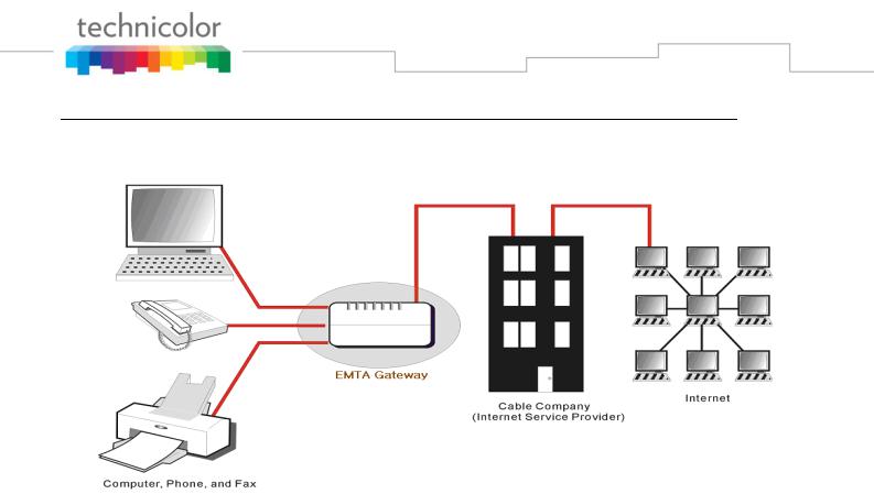
Relationship among the Devices
This illustration shows a cable company that offers DOCSIS/Euro-DOCSIS and PacketCable/EuroPacketCable compliant voice/data services.
Fig. 1-5 Connection overview
What the Modem Does
The Wireless Voice Gateway provides high-speed Internet access as well as cost-effective, toll-quality telephone voice and fax/modem services over residential, commercial, and education subscribers on public and private networks via an existing CATV infrastructure. It can inter-operate with the PacketCable compliant head-end equipment and provide the IP-based voice communications. The IP traffic can transfer between the Wireless Voice Gateway and DOCSIS/Euro-DOCSIS compliant head-end equipment. The data security secures upstream and downstream communications.
What the Modem Needs to Do Its Job
The Right Cable Company: Make sure your local cable company provides data services that use cable TV industry-standard DOCSIS/Euro-DOCSIS compliant and PacketCable/EuroPacketCable compliant technology.
The Internet/Telephony Service Provider (ISP/TSP): Your cable company provides you access to an Internet Service Provider (ISP) and Telephony Service Provider (TSP). The ISP is your gateway to the Internet and provides you with a pipeline to access Internet content on the World Wide Web (WWW). The TSP provides you with telephony access to other modems or other telephony services over the Public Switched Telephone Network (PSTN).
Check with your cable company to make sure you have everything you need to begin; they’ll know if you need to install special software or re-configure your computer to make your cable internet service work for you.
Page 15 / 84

Contact Your Local Cable Company
You will need to contact your cable company to establish an Internet account before you can use your gateway. You should have the following information ready (which you will find on the sticker on the gateway):
 The serial number
 The model number
 The Cable Modem (CM) Media Access Control (MAC) address
 The Terminal Adapter (EMTA) MAC address
 Security information: Service Set Identifier (SSID), Encryption key / passphrase (WPA2-PSK by default), channel number. Default values are indicated underneath the modem on the sticker.
Please check the following with the cable company
The cable service to your home supports DOCSIS/Euro-DOCSIS compliant two-way modem access.
Your internet account has been set up. (The Media Terminal Adapter will provide data service if the cable account is set up but no telephony service is available.)
You have a cable outlet near your PC and it is ready for Cable Modem service.
Note: It is important to supply power to the modem at all times. Keeping your modem plugged in will keep it connected to the Internet. This means that it will always be ready whenever you need.
Important Information
Your cable company should always be consulted before installing a new cable outlet. Do not attempt any rewiring without contacting your cable company first.
Please verify the following on the Wireless Voice Gateway
The Power LED should be lighted when plug-in the power supply.
Connecting the Wireless Voice Gateway to a Single Computer
This section of the manual explains how to connect your Wireless Voice Gateway to the Ethernet port on your computer and install the necessary software. Please refer to Figure 1-5 to help you connect your Digital Cable Modem for the best possible connection.
Page 16 / 84
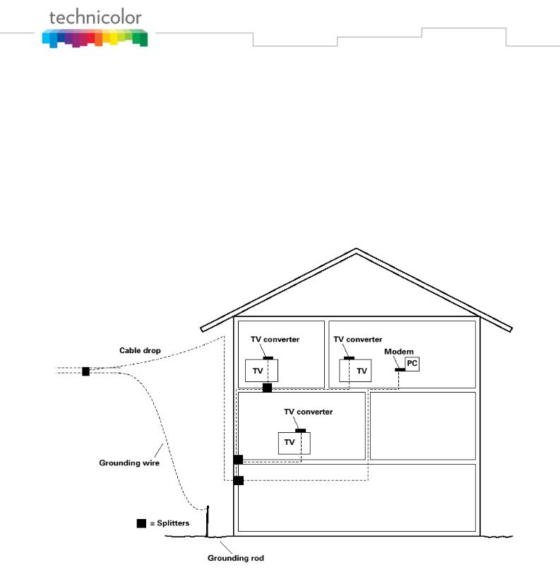
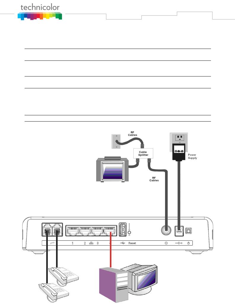
Attaching the Cable TV Wire to the Wireless Voice Gateway
1.Locate the Cable TV wire. You may find it one of three ways:
a.Connected directly to a TV, a Cable TV converter box, or VCR. The line will be connected to the jack, which should be labeled either IN, CABLE IN, CATV, CATV IN, etc.
b.Connected to a wall-mounted cable outlet.
c.Coming out from under a baseboard heater or other location. See Figure 1-6 for the wiring example.
Notes: For optimum performance, be sure to connect your Wireless Voice Gateway to the first point the cable enters your home. The splitter must be rated for at least 1GHz.
Fig. 1-6 Basic Home Wiring
Page 17 / 84
Installation procedure for connecting to the Ethernet interface
Follow these steps for proper installation.
Plug the coaxial cable to the cable wall outlet and the other end to the modem’s cable connector.
Note: To ensure a fast registration of the modem, the coaxial cable must be connected to the modem before it is powered on.
Plug the power supply into the socket of the cable modem and two-pin plug in the AC outlet then press the Power Switch, power on the modem.
Note: Only use the power supply that comes with the modem. Using another power supply can cause damage to the product, and will void the warranty.
Connect an Ethernet cable (direct connection, see below) to the Ethernet port at the back of the computer, and the other end to the ETHERNET port on the rear panel of the cable modem. The modem will seek the appropriate cable signal on the cable television network and go through the initial registration process on its own. The modem is ready for data transfer after the green LED "ONLINE" is lit continuously.
Note: the button "reset" at the back of the modem is used primarily for maintenance.
Fig. 1-7 Connect to the Modem
Page 18 / 84

Telephone or Fax Connection
When properly connected, most telephony devices can be used with the Wireless Voice Gateway just as with a conventional telephone service. To make a normal telephone call, pick up the handset; listen for a dial tone, then dial the desired number. For services such as call waiting, use the hook switch (or FLASH button) to change calls. The following procedures describe some of the possible connection schemes for using telephony devices with the Wireless Voice Gateway.
1.Connect a standard phone line cord directly from the phone (fax machine, answering machine, caller ID box, etc.) to one of the LINE jacks on the Wireless Voice Gateway.
2.If there is a phone line in your home which is NOT connected to another telephone service provider, connect a standard phone line cord from a jack on this line to one of the LINE jacks of the Wireless Voice Gateway. Connect a standard phone line cord directly from the phone (fax machine, answering machine, caller ID box, etc.) to one of the other jacks in the house that uses that line.
3.If you have a multi-line telephone, connect a standard phone line cord (not an RJ-14 type line cord) from the phone to the LINE jacks on the Wireless Voice Gateway. (Other phones can be added to each line by using standard phone line splitters.)
Page 19 / 84

CHAPTER 2: WEB CONFIGURATION
To make sure that you can access the Internet successfully, please check the following first.
1.Make sure the connection (through Ethernet) between the Wireless Voice Gateway and your computer is OK.
2.Make sure the TCP/IP protocol is set properly.
3.Subscribe to a Cable Company.
Accessing the Web Configuration
The Wireless Voice Gateway offers local management capability through a built-in HTTP server and a number of diagnostic and configuration web pages. You can configure the settings on the web page and save them to the device.
Once your host PC is properly configured; please proceed as follows:
1.Start your web browser and type the private IP address of the Wireless Voice Gateway on the URL field: 192.168.0.1
2.After connecting to the device, you will be prompted to select a Country and Language. This page will be brought to you at the first login if the device has been set to user or operator factory defaults. Select the country and language that you preferred and then click “Next” for proceeding to Login page.
Fig2-1 Country and Language page
Page 20 / 84
3.You will be prompted to enter username and password if this is not the first login. By default, the username is “admin” and the password is “admin”.
Fig2-2 Login page
If you login successfully, the main page will appear.
The following page will be displayed if the given username or password is wrong.
Fig2-3 Wrong username/password page
Page 21 / 84
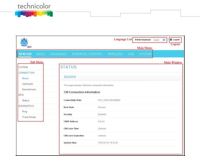
Outline of Web Manager
The main screen will be shown as below.
Fig. 2-4 Outline of Web Manager
Main Menu: the hyperlinks on the top of the page, including STATUS, BASIC, ADVANCED, PARENTAL CONTROL, WIRELESS and SYSTEM items
Sub Menu: the sidebar on the left side of the page indicates the title of this management interface, e.g., Status in this example
Main Window: the current workspace of the web management, containing configuration or status information
Language List: List all of the language supported. Click the drop list and select the language that you preferred.
Logout: Click “Logout” for logging out.
For easy navigation, the pages are organized in groups with group in names main menu. Individual page names within each group are provided in the sub menu and sidebar. So to navigate to a page, click the group hyperlink at the top, then the sub menu for the function, finally choose the title on the sidebar.
Your cable company may not support the reporting of some items of information listed on your gateway’s internal web pages. In such cases, the information field appears blank. This is normal.
Page 22 / 84
Status – Status Web Page Group
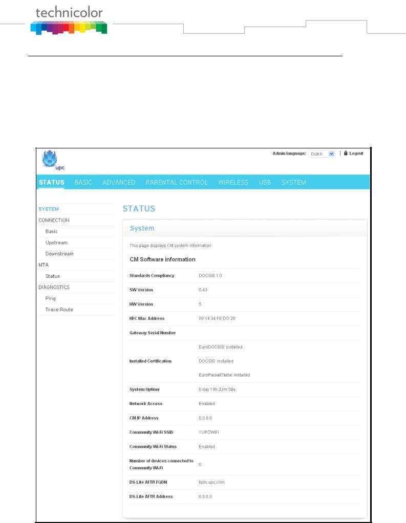
1. System
This page displays system information about your cable modem.
The CM Software information section of this page shows how long your gateway has operated since last time being powered up, and some key information the Cable Modem received during the initialization process with your cable company. If Network Access shows “Allowed,” then your cable company has configured your gateway to have Internet connectivity. If not, you may not have Internet access, and should contact your cable company to resolve this.
Fig.2-5 Status\System
Page 23 / 84
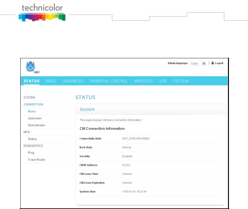
2. Connection/Basic
This page reports current CM basic connection information containing Connectivity State, Boot State, Security, CM IP address, Lease Time, Lease Expiration and current System time. The information can be useful to your cable company’s support technician if you’re having problems.
Fig. 2-6 Status\Connection\Basic
Page 24 / 84
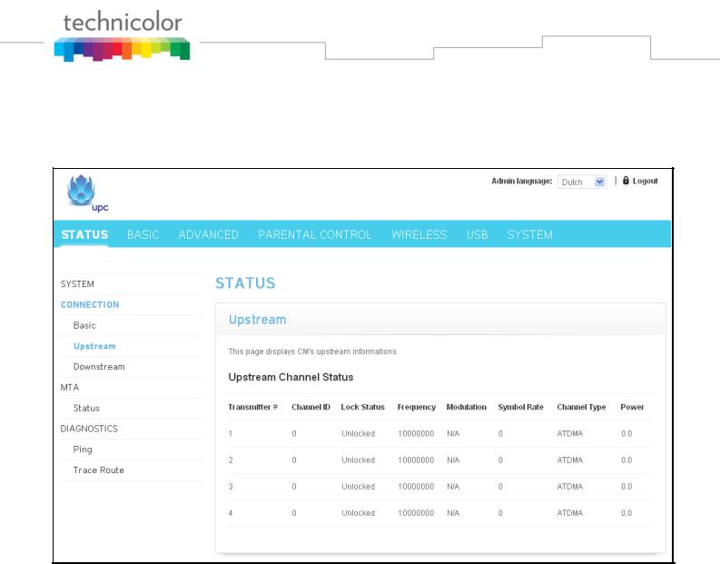
3. Connection/Upstream
This page reports current CM’s upstream information containing Transmitter #, Channel ID, Lock Status, Frequency, Modulation, Symbol Rate, Channel Type and Power. The information can be useful to your cable company’s support technician if you’re having problems.
Fig. 2-7 Status\Connection\Upstream
Page 25 / 84
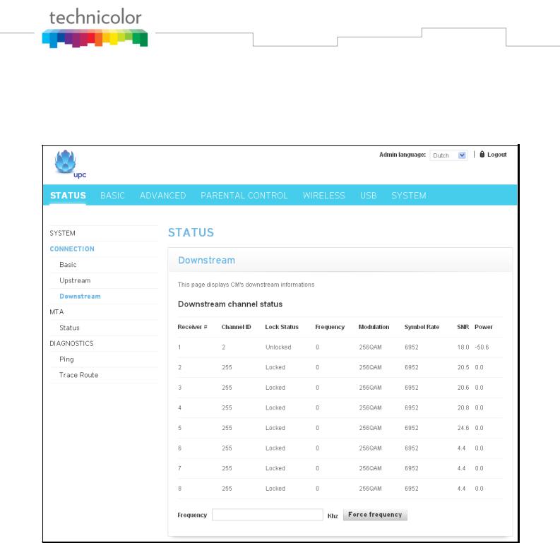
4. Connection/Downstream
This page reports current CM’s downstream information containing Receiver #, Channel ID, Lock Status, Frequency, Modulation, Symbol Rate, SNR and Power. The information can be useful to your cable company’s support technician if you’re having problems. By entering frequency in KHz and clicking
“Force frequency” button, you can force the CM locking to the specified frequency.
Fig. 2-8 Status\Connection\Downstream
Page 26 / 84
 Loading...