

Page 1

SERVICE MANUAL
DOCUMENTATION TECHNIQUE
TECHNISCHE DOKUMENTATION
DOCUMENTAZIONE TECNICA
DOCUMENTACION TECNICA
No copying, translation, modification on other use authorized. All rights reserved worldwide. • Tous droits de reproduction, de traduction, d'adaptation et d'exécution réservés pour tous les pays. • Sämtliche Urheberrechte an diesen Texten und Zeichnungen stehen uns zu. Nachdrucke,
Vervielfältigungen - auch auszugsweise - nur mit unserer vorherigen Zustimmung zulässig. Alle Rechte vorbehalten. • I diritti di riproduzione, di traduzione, e esecuzione sono riservati per tutti i paesi. • Derechos de reproduccion, de traduccion, de adaptacion y de ejecucion reservados para todos los paises.
WARNING : Before servicing this chassis read the safety recommendations.
ATTENTION : Avant toute intervention sur ce châssis, lire les recommandations de sécurité.
ACHTUNG : Vor jedem Eingriff auf diesem Chassis, die Sicherheitsvorschriften lesen.
ATTENZIONE : Prima di intervenire sullo chassis, leggere le norme di sicurezza.
IMPORTANTE : Antes de cualquier intervención, leer las recomendaciones de seguridad.
Code : 351 400 20 - 1200 / 4,6M - DVD DTH4500 Print.
VIDEO
DTH4500
DVD DTH4500
Addition to SM
Additif au SM
Ergänzung zum SM
Aggiornamento del SM
Suplemento al SM
351 272 00
Page 2

Page Page
TECHNICAL SPECIFICATIONS .......................................... 4
SAFETY NOTICE AND PRECAUTIONS ............................... 5
ADJUSTMENT PROCEDURES
1. Handling the optical pickup ..................................... 6
2. Pickup disassembly and assembly .......................... 3
3. Disassembly and assembly
3.1 Cabinet and PCB ...........................................3
3.1.1 Removing the Top Cabinet ............................3
3.1.2 Removing the Door-Tray ............................... 3
3.1.3 Removing the Front-Panel Assembly
and Key PCB .................................................. 4
3.1.4 Removing the Deck Assembly ....................... 4
3.1.5 Removing Main PCB and Jack PCB................ 4
3.2 PCB location ................................................. 4
3.3 Deck .............................................................. 5
3.3.1 Removing PCB Deck Assembly, P/U Deck...... 5
3.3.2 Removing the Tray Disc................................. 5
3.3.3 Removing Slider Housing............................... 5
3.3.4 Removing Housing Assembly ........................ 5
3.3.5 Removing Sub Chassis .................................. 6
3.3.6 Removing Bracket Deck ................................. 6
3.4 Connector Diagram ..................................... 6
BLOCK DIAGRAMS
General Block Diagram .............................................. 7
SCHEMATIC CIRCUIT DIAGRAMS
Servo ...................................................................... 9
AV processing .........................................................13
System Control ....................................................... 17
Display and control ................................................ 21
Audio ...................................................................... 23
Keyboard.................................................................. 26
Headphone .............................................................. 26
Audio 5.1 channel ................................................... 27
Video decoder DTH4200 .......................................... 41
Power supply ........................................................... 43
CD Motor Control DTH4000-DTH4200..................... 46
PRINTED CIRCUIT BOARD LAYOUTS
Jack PCB..................................................................29
Main PCB................................................................. 33
Keyboard ................................................................. 35
CD Motor Control .................................................... 48
ABBREVIATION LIST ....................................................... 57
CONTENTS
DVD DTH4500
2 First issue 12 / 00
: Please refer to DVD DTH4000/4200 Service Manual Part N° 351 272 00
: Se référer à la documentation technique DVD DTH4000/4200 code 351 272 00
: Bitte schlagen Sie im DVD DTH4000/4200 Service Manual 351 272 00 nach
: Consultare la documentazione tecnica del telaio DVD DTH4000/4200, codice : 351 272 00
: Referirse a la documentación básica del DVD DTH4000/4200, código : 351 272 00
Page 3

DVD DTH4000/DTH4200
4 First issue 08 / 00
TECHNICAL SPECIFICATIONS
Power Source : AC 110V - 240V +/- 10%, 50Hz/60Hz
Power Consumption : 18W (approx. 2,4W when power is OFF)
Weight : 3,3 Kg
Dimension : 430 (W) x 89 (H) x 280 (D) mm (excluding protrusions)
Operating Temperature Range : +5 to +35 degrees Celsius (+41° to +95° F)
Operating Humidity Range : 10 to 75% (no condensation)
Signal system : PAL 50 - 60Hz (PAL 625/50, PAL 525/60),
NTSC or PAL 60Hz capable TV set is required to play back NTSC discs.
Disc played :
(1) DVD-Video disc :
PAL and NTSC
12/8 cm single-sided, single-layer
12/8 cm single-sided, double-layer
12/8 cm double-sided, single-layer
12/8 cm double-sided, double-layer
(2) Audio CD :
12/8 cm disc
(3 Video CD :
PAL and NTSC, 12/8 cm side
(4) S-Video CD
(5) most CD-Rs and CD-RWs (DTH4200 only)
Audio signal output :
(1) Frequency response : DVD linear audio 48KHz sampling : 4Hz to 22KHz (EIAJ)
DVD linear audio 96KHz sampling : 4Hz to 44KHz (EIAJ)
CD Audio : 4Hz to 20KHz (EIAJ)
(2) S/N ratio : 105dB (EIAJ)
(3) Dynamic range : DVD linear audio : 100dB (EIAJ)
CD audio : 100dB (EIAJ)
(4) Wow & flutter : below measurable limits
(5) Total harmonic distortion : less than 0.005%
Pickup : Wave length : 655nm, Laser power : CLASS 2
2 Laser diodes (DTH4200 only)
Page 4

DVD DTH4000/DTH4200
First issue 08 / 00 5
PREVENTION OF ELECTRO STATIC DISCHARGE (ESD) TO ELECTROSTATICALLY SENSITIVE
DEVICES (ESD)
Some semiconductor (solid state) devices can be damaged easily by static electricity.
Such components commonly are called Electrostatically Sensitive Devices (ESD). Examples of typical ESD devices are integrated
circuits and some field-effect transistors and semiconductor chip components. The following techniques should be used to help reduce
the incidence of component damage caused by static electricity.
1. Immediately before handling any semiconductor component or semiconductor-equipped assembly, drain off any electrostatic charge
on your body by touching a known earth ground. Alternatively, obtain and wear a commercially available discharging wrist strap
device, which should be removed for potential shock reasons prior to applying power to the unit under test.
2. After removing an electrical assembly equipped with ESD devices, place the assembly on a conductive surface such as aluminum
foil, to prevent electrostatic charge buildup or exposure of the assembly.
3. Use only a grounded-tip soldering iron to solder or unsolder ESD devices.
4. Use only an anti-static solder removal devices. Some solder removal devices not classified as "anti-static" can generate electrical
charges sufficient to damage ESD devices.
5. Do not use freon-propelled chemicals. These can generate electrical charges sufficient to damage ESD devices.
6. Do not remove a replacement ESD device from its protective package until immediately before your are ready to install it. (Most
replacement ESD devices are packaged with leads electrically shorted together by conductive foam, aluminum foil or comparable
conductive materials).
7. Immediately before removing the protective materials from the leads of a replacement ESD device, touch the protective material to
the chassis or circuit assembly into which the device will be installed.
CAUTION : Be sure no power is applied to the chassis or circuit, and observe all other safety precautions.
8. Minimize bodily motions when handling unpackaged replacement ESD devices. (Otherwise harmless motion such as the brushing
together of your clothes fabric or the lifting of your foot from a carpeted floor can generate static electricity sufficient to damage an
ESD device).
There are special components used in this equipment which are imporant for safety, these part are marked by symbol
on the schematic circuit diagrams and replacement part list. It is essential that these safety critical components are replaced
with the manufacture’s specified parts to prevent electric shock, fire, or other hazards. do not attempt to modify the original
design without permission of the manufacturer.
DANGER : Invisible laser radiation when open and interlock failed
or defeated. Avoid direct exposure to beam.
ATTENTION : Le rayon laser est invisible. Eviter l'exposition directe
lors de la maintenance.
VORSICHT BEI Bei geöffneter Schublade und Defekt der Sicherheits -
REPARATUREN : vorrichtungen besteht die Gefahr unsichtbaren
Laserlichts. Niemals direkt in den Laserstrahl sehen.
ATTENZIONE : Il raggio laser è invisibile. Evitare l'esposizione diretta
durante la manutenzione.
IMPORTANTE : El rayo laser es invisible. Evitar la exposición directa
en el momento del mantenimiento.
CLASS 1 LASER PRODUCT
APPAREIL A LASER DE CLASSE 1
LASER KLASSE 1
APARATO CON LASER DE CLASE 1
APPARECCHIO CON LASER DI CLASSE 1
IMPORTANT SAFETY NOTICE
Page 5

DVD DTH4000/DTH4200
6 First issue 08 / 00
ADJUSTMENT PROCEDURES
1. Handling the optical pickup
The laser diode used in the optical pickup may break down due to
potential differences caused by electricity produced by clothing or
the human body, care should therefore be taken to prevent
electrostatic discharge whilst repairing the optical pickup.
The following method is recommended.
(1) Place a conductive sheet on the work bench (The black sheet
used for wrapping repair parts.)
(2) Place the set on the conductive sheet so that the chassis is
grounded to the sheet.
(3) Place your hands on the conductive sheet (doing this gives
them the same ground as the sheet.)
(4) Remove the optical pickup block
(5) Perform work on top of the conductive sheet. Be careful not to
let your clothes or any other static sources to touch the unit.
* Grounding the Human Body, use an antistatic wrist strap to
discharge static electricity from your body.
* Grounding the work place, use either an antistatic matt or a
sheet of steel on the area where the optical pickup is to be
placed and ground the matt/sheet.
Fig. 1-3
(6) Short the short terminal on the PCB, which is in-side the
Pickup Assembly, before replacing the Pickup. (The short
terminal is shorted when the Pickup Assembly is being lifted or
moved.)
(7) After replacing the Pickup, open the short terminal on the
PCB.
Page 6

DVD
DTH4500
First issue 12 / 00 3
ADJUSTMENT PROCEDURES
2. Pickup Disassembly and Assembly
2-1 Disassembly
1) Remove the power cable.
2) Switch SW3 (on Deck PCB) to "OFF" before disconnecting the
flat cable (DCN1 inserted into Main PCB see Fig. 1-4).
3) Remove the deck.
4) Remove the deck PCB.
2-2 Assembly
1) Replace the Pickup.
2) Refit the deck PCB.
3) Refit the deck.
4) Insert flat cable into DCN1 (Main PCB) and switch SW3 (on
deck PCB) to "ON". (see Fig. 1-4)
Note : If the assembly and disassembly are not done in correct
sequence, the Pickup may be damaged.
Fig. 1-4
3. Disassembly and Assembly
3-1 Cabinet and PCB
Note : Reassemble in reverse order.
3-1-1 Removing the Top Cabinet
1) Remove 3 screws 1 on the back of the Top Cabinet.
2) Remove the 2 screws 2 on the left side and 3 on the right
side.
3) Lift the Top Cabinet up in the direction of the arrow.
Fig. 3-1-1
3-1-2 Removing the Door-Tray
1) Switch the power on and open Tray 1.
2) Pull Door-Tray 2 in direction of arrow "A".
3) Close Tray 1 and Switch the power off.
Note : If Tray 1 cannot be opened, insert a Screw driver 4 into
Emergency hole 3 (as shown in detailed drawing) and then turn it
in the direction of arrow "B". Open the Tray manually.
Fig. 3-1-2
FLAT-CABLE
TO MAIN PCB
(DCN1)
SW3
ON
OFF
1 3 SCREWS
2 1 SCREW
3 1 SCREW
"A"
TRAY
DOOR-TRAY
<Side View>
EMERGENCY HOLE
SCREW DRIVER
"B"
Page 7
DVD DTH4500
4 First issue 12 / 00
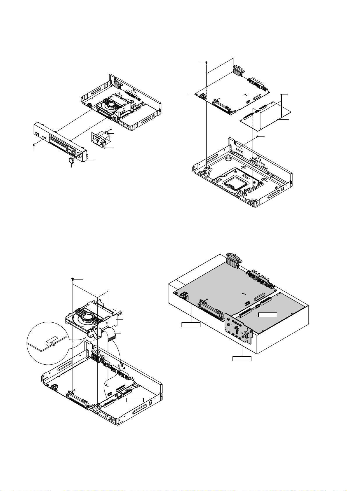
3-1-3 Removing the Front-Panel Assembly and Key
PCB
1) Remove Knob-Volume 1 and Knob-Shuttle 2
2) Remove Front-Panel Assembly 3.
3) Remove 5 screws 4 and Ground Rear 5.
4) Remove Key PCB 6.
Fig. 3-1-3
3-1-4 Removing the Deck Assembly
1) Remove 4 Screws 1 from the Assembly Deck and lift it up.
CAUTION :
a) When disassembling, switch SW3 to "OFF" on the Deck
PCB and remove the Flat-Cable connected to DCN1 on Main
PCB.
b) When assembling, insert the Flat-Cable into the DCN1 on
Main PCB and switch SW3 to "ON" on the Deck PCB.
Fig. 3-1-4
3-1-5 Removing Main PCB and Jack PCB
1) Remove 1 Screw 1.
2) Remove 2 screws 2 and lift Jack PCB 3 up.
3) Remove 3 screws 4 and lift Main PCB 5 up.
Fig. 3-1-5
3-2 PCB Location
Fig. 3-2
DECK-ASS'Y
1 3 SCREWS
DCN1
MAIN PCB
SW3
OFF
ON
FLAT-CABLE
1 SCREW
MAIN PCB
3 SCREWS
2 SCREWS
JACK PCB
MAIN PCB
KEY PCB
JACK PCB
5 SCREWS
KEY PCB
GROUND REAR
ASS'Y FRONT-CABINET
KNOB-VOLUME
KNOB-SHUTTLE
Page 8

3-3 Deck
3-3-1 Removing PCB Deck Assembly, P/U Deck
1) Remove the soldering of SLED+, SLED- 1 and TM+, TM- 2.
2) Disconnect CN3 3, CN2 4.
3) Remove 1 Screw 5 and lift the PCB Deck 6 up.
4) Remove 1 Screw 7.
5) Push the Hook 8 in the direction of arrow "A" and lift the
P/U Deck Assembly 9 up in the direction of arrow "B".
Fig. 3-3-1
3-3-2 Removing the Tray Disc
1) Insert Screw Driver 1 into Emergency Hole 2 and push Sider
Housing 3 in the direction of arrow "A".
2) When Tray Disc 4 comes out little, pull it in the direction of
arrow "B" by hand.
3) Pull Tray Disc 4 to disassemble, while pushing 2 Stoppers 5
(left, right) in the direction of arrow "C" and "D" simultaneously.
Fig. 3-3-2
3-3-3 Removing Slider Housing
1) Push Slider Housing 1 in the direction of arrow "A".
2) Lift Slider Housing 2 up.
Fig. 3-3-3
3-3-4 Removing Housing Assembly
1) Remove Belt 1 and 1 Screw 2.
2) Remove 1 screw 3 and lift the Pulley Gear 4 up.
3) Push Hook 5 in the direction of arrow "A" and lift the
Gear Tray 6 and the Gear Housing 7 up.
4) Push the 4 Hooks 8 bottom side in the direction of arrow "B"
and lift the Motor Load Assembly 9 up.
5) Remove Clamper Assembly J.
Fig. 3-3-4
DVD
DTH4500
First issue 12 / 00 5
"A"
SLIDER HOUSING
Assembly
PUSH
BELT
1 SCREW
1 SCREW
PULLEY GEAR
HOOK
"A"
GEAR TRAY
GEAR HOUSING
MOTOR LOAD ASS'Y
CLAMPER ASS'Y
<Bottom Side>
4 HOOKS
"B"
"B"
"B"
"B"
SLED+/SLED-
TM+/TM-
1 SCREW
DECK PCB
1 SCREW
HOOK
"B"
"A"
ASS'Y P/U DECK
<Assembly Point>
CN3
CN2
5 STOPPER
4 TRAY DISC
3 SLIDER HOUSING
5 STOPPER
2 EMERGENCY HOLE
1 SCREW DRIVER
"B"
"A"
"C"
"D"
Page 9

3-3-5 Removing Sub Chassis
1) Remove 4 Screws 1.
2) Lift Assembly Braket Deck 2 up.
Fig. 3-3-5
3-4 Connector Diagram
3-3-6 Removing Bracket Deck
1) Remove Washer 1.
2) Remove Gear Feed B 2, Gear Feed A 3.
3) Remove 2 Screws 4.
4) Remove Shaft Pick-up 5 and Pick-up Assembly 6.
5) Remove screw 7.
6) Remove 2 screws 8.
7) Remove 3 Springs Spindle 9 and Motor Spindle Assembly J.
Fig. 3-3-6
DVD DTH4500
6 First issue 12 / 00
DECK-ASS'Y
CT3
KEY PCB
CT1
MAIN PCB
JACK PCB
CT2
CT4
NO. CONNECTOR NO. DIRECTION CONNECTOR NO. NO.
FCN1 KEY PCB JACK PCB CON5
PCNS1 JACK PCB MAIN PCB PCN1
FPC DECK-ASS'Y MAIN
PCB DCN1
CN1 JACK PCB MAIN PCB CN8
CT1
CT2
CT3
CT4
2 SCREW
WASHER
GEAR FEED B
2 SCREWS
1 SCREW
SHAFT PICK-UP
GEAR FEED A
PICK-UP ASS'Y
SPRING SPINDLE
MOTOR SPINDLE
4 SC REWS
ASSY-BRAK DECK
Page 10

DVD DTH4500
First issue 12 / 00 7
8
GENERAL BLOCK DIAGRAM - SYNOPTIQUE GÉNÉRAL - BLOCKSCHALTBILD ALLGEMEIN - SCHEMA A BLOCCHI GENERALE - ESQUEMA DE BLOQUES GENERAL
DECK ASS'Y (DP-5)
SIC3
(KA3017)
Actuator & Motor Driver
Spindle/Sied/Tray Motor Pick-up & I/V Amp
DIC2 4M DRAM
ZIC2/3 SDRAM X 2
MIC4 2K EEPROM
Remote Control FLT Display
MIC2 8M EPROM
Coaxial
SIC1
(KS1454)
Servo + DSP
RIC1
(KS1462)
RF Amp & DPD
MIC1
(TMP95C265F)
Main Controller
FIC1
AC3 DECODER
(uPD780232)
Front Controller
ZIC1 (ZiVA-4.1)
A/V Decoder
Lt
Rt
Post
Filter
Optical
A/V
Decoder
AC3 &
MPEG 5.1
Video
Encoder
(4DAC)
AUDIO
DSP
CSS
INPUT
FIFO
&
DEMUX
AIC1 (AK4393)
2-CH Audio DAC
Down-L/R
MIC3 1M SDRAM
SCIC3
(14053)
Switch
SCIC4
(NJM2267)
AMP
SCIC5
(14053)
Switch
SCIC6
(BA7660)
AMP
SCIC1, 2
(14053)
Switch
SCJ1 (VCR)
SCJ1 (TV)
RGB_DVD
CVBS_DVD
COMP
Y/B/Pb
L/R_DVD
CVBS_TV_IN
CVBS_TV_OUT
L/R_TV
RGB_TV
CVBS_VCR
_IN
CVBS_VCR_IN
RGB_VCR
L/R_VCR
Post Filter
Yout
Cout
CVBS
Post Filter
VIC1 (BA7660)
6dB AMP
F/L
F/R
R/L
R/R
S/W
C/T
Page 11

9
DVD DTH4500
10 First issue 12 / 00
SERVO SCHEMATIC DIA GRAM - SCHEMA DES CIRCUITS D'ASSERVISSEMENTS - SCHALTBILD SER VO - SCHEMA DEI CIRCUITI SER VO - ESQUEMA DE LOS CIRCUITOS SERV O MECANISMO
MAIN
Page 12

SERVO MEASUREMENTS - MESURES DES CIRCUITS D'ASSERVISSEMENTS - MESSUNGEN SERV O - MISURE DEI CIRCUITI SERVO - MEDIDAS DE LOS CIRCUITOS SERVO MECANISMO
1 2.5 2.5 2.5 2.5
2 2.5 2.5 2.5 2.5
3 2.5 2.5 2.5 2.5
4 2.5 2.5 2.5 2.5
5 2.5 2.5 2.5 2.5
6 1.3 1.3 1.3 1.3
7 1.3 1.3 1.4 1.5
8 1.3 1.3 1.3 1.3
9 2.5 2.5 2.5 2.5
10 2.5 2.5 2.7 2.5
11 2.5 2.5 2.7 2.5
12 2.5 2.5 2.6 2.5
13 2.5 2.5 2.6 2.5
14 5 5 5 5.1
15 2.5 2.5 2.5 2.5
16 2.5 2.5 2.8 2.5
17 2.5 2.5 2.8 2.5
181111
195555
200000
21 4.9 0 3.8 5
22 0 0 0.2 0
230000
24 1.6 1.7 1.7 1.7
25 1.7 1.7 1.7 1.7
26 1.7 1.7 1.7 1.7
27 3.3 3.3 3.3 3.3
28 1.7 1.7 1.7 1.7
29 2.6 1.4 2.5 1.4
30 2.5 2.5 2.5 2.5
31 3.3 2.5 3.3 2.5
32 1.6 2.4 1.6 2.5
33 1.6 0 1.5 0
340000
35 0 5 0 5.1
36 3.5 2.5 3.4 2.5
37 3.5 2.6 3.5 2.8
38 3.4 2.5 3.4 2.5
39 3.5 2.6 3.4 2.6
40 5.1 5.1 5.1 5.1
PLAY STOP PLAY STOP
DVD CD
MODE
PIN
41 0 0 0 0
42 0 0 0 0
43 2.5 2.5 2.5 2.5
44 0 0 0 0
45 5 5 5 5.1
46 0 5.1 0 5.1
47 2.5 2.5 0.1 0.1
48 2.5 2.5 0.1 0.1
49 0 5.1 5.1 5.1
50 2.5 2.5 1.4 1.5
51 1.3 1.3 0 0
52 0 0 0 0
53 2.5 2.5 1.4 1.5
54 1.3 1.3 0 0
55 0 0 0 0
56 5.1 5.1 5.1 5.2
57 0 0 0 0
58 5.1 5.1 5.1 5.1
59 2.4 0.5 2 1.2
60 5 5 5 5
61 2.6 0.3 2.2 1.1
62 3.3 0.2 2.3 1.3
63 2 2.5 2.1 2.5
64 3.1 2.6 2.8 2.6
65 2.5 2.5 2.5 2.5
66 5 5 5 5.1
67 1.6 1.6 1.7 1.7
68 4.7 4.7 4.6 4.7
69 2.5 2.5 2.5 2.5
70 1.6 1.6 1.7 1.7
71 2.5 2.6 2.5 2.5
72 2.5 2.6 2.5 2.5
73 2.4 2.4 3.9 4
74 0 0 0 0
75 1.3 1.3 1.3 1.3
76 2.2 2.5 2.3 2.5
77 3 2.5 2.9 2.5
78 1.1 1.2 1.1 1.2
79 5 5 5 5.1
80 2.5 2.5 2.5 2.5
PLAY STOP PLAY STOP
DVD CD
MODE
PIN
RIC1 (KS1462)
10 0 0 0
2 1.2 1.2 1.2 1.2
3 3.4 3.4 3.4 3.4
4 3.4 3.4 3.4 3.4
5 1.5 3.4 1.5 3
6 1.5 2.5 1.5 3
7 1.2 1.2 1.2 1.7
8 0 0 0 1.7
9 1.4 0.7 0.7 0.7
10 1.7 1.7 1.7 1.7
110000
12 1.7 1.7 1.7 1.7
13 1.7 1.7 1.7 1.7
14 1.7 1.7 1.7 1.7
15 1.7 1.7 1.7 1.7
16 1.8 1.6 1.7 1.6
17 1.9 1.7 1.7 1.7
18 3.4 3.4 3.4 3.4
19 1.7 0.1 1.7 0
20 1.7 1.7 1.7 1.7
21 1.7 1.7 1.7 1.6
22 1.7 1.7 1.7 1.6
23 1.7 1.7 1.7 1.7
24 1.7 3.3 1.7 0.1
25 1.7 1.7 1.7 1.7
26 1.7 1.7 1.7 1.7
27 1.7 1.7 1.7 1.6
28 1.9 1.7 1.8 1.7
29 0.2 1.7 1 1.1
30 0 0.1 0 0
31 1.7 1.7 1.7 1.7
32 1.7 1.7 1.9 1.7
33 1.6 1.6 1.6 1.6
34 1.7 1.7 1.7 1.7
35 1.8 1.6 1.8 1.6
360000
370000
380000
390000
400000
PLAY STOP PLAY STOP
DVD CD
MODE
PIN
41 0 0 0 0
42 0 0 0 0
43 1.6 1.5 1.5 1.4
44 0 0 0 0
45 1.5 1.4 1.4 1.5
46 0.2 0 0.2 0.4
47 0.2 0 0.2 0.4
48 0.2 0 0.2 0.4
49 0.2 0 0.1 0.2
50 0.2 0 0.2 0.4
51 0.2 0 0.1 0.2
52 0.2 0 0.2 0.4
53 0.2 0 0.1 0.2
54 0.2 0 0 0
55 3.2 3.2 3.2 3.2
56 5.1 5.2 5.1 5.2
57 2.4 2.4 4.9 4.8
58 5 5.2 5 5
59 5.1 5.2 5.1 5.2
60 5 5.2 5.1 5
61 5.1 5.2 5.2 5.2
62 3.8 3.8 5 5
63 3.9 3.8 5 5
64 5.1 5.2 5.2 5.2
65 3.2 3.2 3.2 3.2
66 1.4 1.5 2.4 2.5
67 1.4 1.6 0 0
68 1.4 1.6 2.4 2.7
69 1.4 1.6 0 0
70 1.4 1.6 2.4 2.5
71 1.4 1.4 0 0
72 1.4 1.5 2.4 2.1
73 1.4 1.5 0 0
74 1.4 1.5 2.4 2.3
75 1.4 1.5 0 0
76 1.4 1.5 2.4 2.4
77 1.4 1.5 0 0
78 1.4 1.6 2.4 2.6
79 1.4 1.5 0 0
80 0 0 0 0
PLAY STOP PLAY STOP
DVD CD
MODE
PIN
810000
82 1.5 1.6 2.4 2.5
83 1.5 1.5 0 0
840000
850000
860000
87 1.3 1.5 2.5 2.5
88 5.1 0 0 0
89 3.2 3.2 3.2 3.2
90 2.6 2.6 2.6 2.6
91 2.6 2.6 2.6 2.6
92 2.5 2.5 2.5 2.5
93 3.2 3.2 3.2 3.2
94 2.5 2.5 2.5 2.5
95 2.5 2.5 2.5 2.5
96 0 0 0 2.6
97 2.5 2.5 2.5 5.2
98 3.2 3.2 3.2 3.2
99 5.1 5.2 5.1 5.2
100 0 0 0 0
101 4.7 5.2 5.1 0.1
102 5 5.2 5.1 5.2
103 3.2 3.2 3.2 3.2
104 1.8 1.8 1.5 1.5
105 2.3 2.3 2 1.9
106 2 2 2 2
107 1.7 1.6 1.9 1.9
108 1.7 1.7 1.9 1.9
109 1.7 2.1 2.2 2.2
110 2.5 2.6 3.1 3.1
111 1.7 1.8 1.9 2
112 0 0 0 0
113 5.1 5.1 5.1 5.2
114 2.5 2.4 2.5 2.5
115 5.1 5.2 5.1 5.2
116 5.1 5.2 5.1 5.2
117 5.1 5.2 5.1 5.2
118 5.1 5.2 5.1 5.2
119 5.1 5.2 5.1 5.2
120 0 0 0 0
PLAY STOP PLAY STOP
DVD CD
MODE
PIN
121 5.1 5.1 5.1 5.2
122 2.1 5.1 5.1 2.1
123 5.1 5.1 5.1 5.2
124 0 0 0 0
125 0 0 0 0
126 4.4 5.1 5.1 5.2
127 2.4 5.1 5.1 5.2
128 2.4 0 0 0
129 3.2 3.2 3.2 3.2
130 2.5 2.8 2.8 2.7
131 2.5 0.1 0.1 0
132 2.5 2.6 2.6 2.6
133 2.5 0.1 0.1 2.6
134 2.5 0 0 5.2
135 2.5 2.5 2.5 2.5
136 2.5 2.6 2.6 2.6
137 2.5 1.7 1.7 0
138 0 0 0
139 0 0 0 0
140 0 0 0 0
141 0 0 0 0
142 0 0 0 0
143 0 0 0 0
144 0 0 0 0
145 0 0 0 0
146 0 0 0 0
147 3.2 3.2 3.2 3.2
148 5.1 5.1 5.1 5.2
149 5.1 0 0 0
150 0 0 0 0
151 5.1 5.1 5.1 0
152 5.1 5.1 5.1 0
153 1.9 1.7 1.7 1.7
154 1.9 2 2 1.7
155 0 0 0 5.1
156 0 0 0 0
157 0 0 0 0
158 1.5 1.5 1.5 1.3
159 0 0 0 0
160 0 0 0 0
PLAY STOP PLAY STOP
DVD CD
MODE
PIN
SIC1 (KS1454)
1 0.1 0.1 0.1 0.1
2 2.3 5.0 2.3 5.0
3 2.5 2.5 2.5 2.5
4 2.7 2.5 2.7 2.5
5 5.0 5.0 5.0 5.0
6 0.0 0.0 0.0 0.0
7 0.0 0.0 0.0 0.0
8 7.9 8.0 7.9 8.0
9 7.9 8.0 7.9 8.0
10 5.0 0.0 5.0 0.0
11 0.0 5.0 0.0 5.0
12 0.0 0.0 0.0 0.0
13 0.0 0.0 0.0 0.0
14 5.9 0.0 6.6 0.0
15 6.0 0.0 6.6 0.0
16 5.9 0.0 6.6 0.0
17 2.5 2.5 2.5 2.5
18 2.5 2.5 2.5 2.5
19 2.5 2.5 2.5 2.5
20 7.9 8.0 7.9 8.0
21 7.9 8.0 7.9 8.0
22 2.5 2.5 2.5 2.5
23 2.5 2.5 2.5 2.5
24 2.5 2.5 2.5 2.5
25 2.5 2.5 2.5 2.5
26 3.7 4.0 3.5 4.0
27 4.2 4.0 4.2 4.0
28 4.0 4.0 4.0 4.0
29 4.0 4.0 4.0 4.0
30 0.0 0.0 0.0 0.0
31 0.0 0.0 0.0 0.0
32 3.9 4.0 3.9 4.0
33 3.9 4.0 3.9 4.0
34 7.9 8.0 7.9 8.0
35 4.0 4.0 4.0 4.0
36 3.9 3.9 3.9 3.9
37 0.0 0.0 0.0 0.0
38 0.0 0.0 0.0 0.0
39 0.0 0.0 0.0 0.0
40 7.9 8.0 7.9 8.0
41 2.5 2.5 2.5 2.5
42 0.0 0.0 0.0 0.0
43 2.5 2.6 2.5 2.6
44 2.5 2.5 2.5 2.5
45 2.5 2.6 2.5 2.6
46 2.5 2.4 2.5 2.4
47 2.5 2.4 2.5 2.4
48 2.5 2.4 2.5 2.4
PLAY STOP PLAY STOP
DVD CD
SIC3 (KA3017)
MODE
PIN
0
DTH4500
DVD
First issue 12 / 00 11
12
Page 13

13
DVD DTH4500
14 First issue 12 / 00
14
13 12 11 10 9 8
7654321
MAIN
AV PROCESSING SCHEMATIC DIAGRAM - SCHEMA DU TRAITEMENT AV - SCHALTBILD AV-VERARBEITUNG - SCHEMA ELABORAZIONE AV - ESQUEMA DEL TRATAMIENTO AV
Page 14

DVD DTH4500
First issue 12 / 00 15
16
AV PROCESSING MEASUREMENTS - MESURES DU TRAITEMENT AV - MESSUNGEN AV-VERARBEITUNG - MISURE ELABORAZIONE AV - MEDIDAS DEL TRATAMIENTO AV
PLAY STOP PLAY STOP
DVD CD
MODE
PIN
1 2.4 2.4 2.4 2.4
2 4.9 4.9 4.9 4.9
3 3.2 3.2 3.2 3.2
4 3.2 3.2 3.2 3.2
5 5.0 5.0 5.0 5.0
6 0.0 0.0 0.0 0.0
7 3.2 3.2 3.2 3.2
8 3.2 3.2 3.2 3.2
9 2.7 2.7 2.7 2.7
10 2.7 2.7 2.7 2.7
11 2.7 2.7 2.7 2.7
12 2.7 2.7 2.7 2.7
13 2.4 2.4 2.4 2.4
14 0.0 0.0 0.0 0.0
15 2.7 2.7 2.7 2.7
16 2.7 2.7 2.7 2.7
17 2.7 2.7 2.7 2.7
18 2.7 2.7 2.7 2.7
19 0.0 0.0 0.0 0.0
20 3.2 3.2 3.2 3.2
21 0.2 0.2 0.2 0.2
22 0.2 0.2 0.2 0.2
23 0.2 0.2 0.2 0.2
24 0.2 0.2 0.2 0.2
25 0.2 0.2 0.2 0.2
26 0.2 0.2 0.2 0.2
27 0.2 0.2 0.2 0.2
28 0.2 0.2 0.2 0.2
29 3.2 3.2 3.2 3.2
30 2.7 2.7 2.7 2.7
31 0.0 0.0 0.0 0.0
32 3.2 3.2 3.2 3.2
33 3.2 3.2 3.2 3.2
34 3.2 3.2 3.2 3.2
35 3.2 3.2 3.2 3.2
36 3.2 3.2 3.2 3.2
37 0.0 0.0 0.0 0.0
38 3.2 3.2 3.2 3.2
39 3.2 3.2 3.2 3.2
40 3.2 3.2 3.2 3.2
41 3.2 3.2 3.2 3.2
42 3.2 3.2 3.2 3.2
43 0.0 0.0 0.0 0.0
44 0.0 0.0 0.0 0.0
45 3.2 3.2 3.2 3.2
PLAY STOP PLAY STOP
DVD CD
MODE
PIN
46 0.0 0.0 0.0 0.0
47 0.0 0.0 0.0 0.0
48 0.0 0.0 0.0 0.0
49 0.0 0.0 0.0 0.0
50 0.0 0.0 0.0 0.0
51 0.0 0.0 0.0 0.0
52 0.0 0.0 0.0 0.0
53 0.8 0.8 0.8 0.8
54 1.0 1.0 1.0 1.0
55 3.2 3.2 3.2 3.2
56 0.0 0.0 0.0 0.0
57 1.2 0.9 1.2 0.9
58 1.2 0.9 1.2 0.9
59 1.2 0.9 1.2 0.9
60 1.2 0.9 1.2 0.9
61 1.2 0.9 1.2 0.9
62 1.2 0.9 1.2 0.9
63 1.2 0.9 1.2 0.9
64 3.2 3.2 3.2 3.2
65 0.0 0.0 0.0 0.0
66 1.4 0.9 1.4 0.9
67 2.4 2.4 2.4 2.4
68 0.0 0.0 0.0 0.0
69 1.4 0.9 1.4 0.9
70 1.4 0.9 1.4 0.9
71 1.4 0.9 1.4 0.9
72 1.4 0.9 1.4 0.9
73 1.4 0.9 1.4 0.9
74 3.2 3.2 3.2 3.2
75 0.0 0.0 0.0 0.0
76 1.4 0.9 1.4 0.9
77 0.0 0.0 0.0 0.0
78 1.6 1.6 1.6 1.6
79 3.2 3.2 3.2 3.2
80 0.8 0.5 0.6 0.5
81 0.8 0.5 0.6 0.4
82 3.2 3.2 3.2 3.2
83 0.0 0.0 0.0 0.0
84 1.4 0.9 1.4 0.9
85 1.4 0.9 1.4 0.9
86 1.4 0.9 1.4 0.9
87 3.2 3.2 3.2 3.2
88 0.0 0.0 0.0 0.0
89 1.3 1.5 1.3 1.5
90 3.1 3.1 3.1 3.1
PLAY STOP PLAY STOP
DVD CD
MODE
PIN
ZIC1 (ZIVA4.1)
91 1.5 1.5 1.5 1.5
92 3.2 3.2 3.2 3.2
93 0.0 0.0 0.0 0.0
94 2.7 2.4 2.7 2.4
95 2.1 2.3 2.1 2.3
96 3.1 3.1 3.0 3.0
97 1.2 1.3 1.2 1.3
98 0.3 0.3 0.3 0.3
99 0.4 0.7 0.4 0.7
100 3.2 3.2 3.2 3.2
101 0.0 0.0 0.0 0.0
102 1.4 1.2 1.4 1.2
103 1.4 1.4 1.4 1.4
104 1.4 1.4 1.4 1.4
105 0.0 0.0 0.0 0.0
106 0.0 0.0 0.0 0.0
107 0.0 0.0 0.0 0.0
108 0.0 0.0 0.0 0.0
109 0.2 0.2 0.2 0.2
110 0.0 0.0 0.0 0.0
111 3.2 3.2 3.2 3.2
112 3.2 3.2 3.2 3.2
113 1.6 1.6 1.6 1.6
114 1.6 1.6 1.6 1.6
115 3.2 3.2 3.2 3.2
116 0.0 0.0 0.0 0.0
117 0.0 0.0 0.0 0.0
118 0.0 0.0 0.0 0.0
119 0.0 0.0 0.0 0.0
120 1.6 0.0 1.6 0.0
121 1.6 0.0 1.6 0.0
122 1.6 1.6 1.6 1.6
123 3.2 3.2 3.2 3.2
124 0.0 0.0 0.0 0.0
125 1.6 1.6 1.6 1.6
126 1.6 1.6 1.6 1.6
127 1.6 1.6 1.6 1.6
128 2.4 2.4 2.4 2.4
129 0.0 0.0 0.0 0.0
130 0.0 0.0 0.0 0.0
131 0.0 0.0 0.0 0.0
132 0.0 0.0 0.0 0.0
133 0.6 0.5 0.6 0.5
134 3.2 3.2 3.2 3.2
135 3.2 3.2 3.2 3.2
136 0.0 0.0 0.0 0.0
137 0.0 0.0 0.0 0.0
138 0.0 0.0 0.0 0.0
139 0.6 0.5 0.6 0.5
140 3.2 3.2 3.2 3.2
141 3.2 3.2 3.2 3.2
142 0.0 0.0 0.0 0.0
143 0.0 0.0 0.0 0.0
144 0.0 0.0 0.0 0.0
145 0.7 0.5 0.7 0.5
146 3.2 3.2 3.2 3.2
147 3.2 3.2 3.2 3.2
148 0.0 0.0 0.0 0.0
149 0.0 0.0 0.0 0.0
150 0.0 0.0 0.0 0.0
151 0.5 0.5 0.5 0.5
152 3.2 3.2 3.2 3.2
153 3.2 3.2 3.2 3.2
154 0.0 0.0 0.0 0.0
155 1.3 1.3 1.3 1.3
156 3.2 3.2 3.2 3.2
157 0.0 0.0 0.0 0.0
158 3.2 3.2 3.2 3.2
159 1.6 1.6 1.6 1.6
160 3.2 3.2 3.2 3.2
161 2.5 0.0 2.5 0.0
162 2.5 0.0 2.5 0.0
163 2.5 0.0 2.5 0.0
164 2.5 0.0 2.5 0.0
165 2.5 0.0 2.5 0.0
166 0.0 0.0 0.0 0.0
167 3.2 3.2 3.2 3.2
168 2.5 0.0 2.5 0.0
169 2.5 0.0 2.5 0.0
170 2.5 0.0 2.5 0.0
171 4.0 5.0 5.0 5.0
172 2.5 2.0 2.5 1.6
173 2.4 2.4 2.4 2.4
174 0.0 0.0 0.0 0.0
175 3.2 3.2 3.2 3.2
176 0.0 0.0 0.0 0.0
177 3.2 3.2 3.2 3.2
178 0.0 0.0 0.0 0.0
179 3.2 3.2 3.2 3.2
180 0.0 0.0 0.0 0.0
PLAY STOP PLAY STOP
DVD CD
MODE
PIN
181 3.2 3.2 3.2 3.2
182 2.5 2.5 2.5 2.5
183 2.5 2.5 2.5 2.5
184 2.5 2.5 2.5 2.5
185 3.2 3.2 3.2 3.2
186 3.2 3.2 3.2 3.2
187 3.2 3.2 3.2 3.2
188 0.0 0.0 0.0 0.0
189 3.2 3.2 3.2 3.2
190 3.2 3.2 3.2 3.2
191 0.0 0.0 0.0 0.0
192 3.2 3.2 3.2 3.2
193 3.2 3.2 3.2 3.2
194 3.2 3.2 3.2 3.2
195 3.2 3.2 3.2 3.2
196 3.2 3.2 3.2 3.2
197 2.4 2.3 2.4 2.3
198 0.0 0.0 0.0 0.0
199 2.2 2.2 2.2 2.2
200 2.0 2.0 2.0 2.0
201 1.6 1.6 1.6 1.6
202 1.6 1.6 1.6 1.6
203 1.8 2.0 1.8 2.0
204 3.2 3.2 3.2 3.2
205 0.0 0.0 0.0 0.0
206 1.6 1.6 1.6 1.6
207 1.6 1.6 1.6 1.6
208 4.9 5.0 4.9 5.0
PLAY STOP PLAY STOP
DVD CD
MODE
PIN
ZIC1 (ZIVA4.1)
1 3.2 3.2 3.2 3.2
2 1.0 0.7 1.0 0.7
3 1.0 0.7 1.0 0.7
4 0.0 0.0 0.0 0.0
5 1.0 1.0 1.0 1.0
6 0.9 0.9 0.9 0.9
7 3.2 3.2 3.2 3.2
8 1.3 0.7 0.6 0.8
9 1.0 1.0 0.8 1.2
10 0.0 0.0 0.0 0.0
11 1.0 1.0 0.6 1.1
12 1.6 1.0 0.6 1.2
13 3.2 3.2 3.2 3.2
14 0.0 0.0 0.0 0.0
15 3.0 3.1 3.0 3.1
16 1.4 1.5 1.4 1.5
17 2.7 2.4 3.2 2.6
18 2.2 2.3 2.2 2.3
19 1.2 1.1 1.2 1.1
20 0.5 0.7 0.5 0.7
21 0.5 0.7 0.5 0.7
22 1.4 1.2 1.4 1.2
23 1.4 1.4 1.4 1.4
24 1.3 1.3 1.3 1.3
25 3.2 3.2 3.2 3.2
26 0.0 0.0 0.0 0.0
27 1.4 1.5 1.4 1.5
28 1.5 1.5 1.5 1.5
29 1.4 1.2 1.4 1.2
30 1.4 1.3 1.4 1.3
31 0.7 0.6 0.7 0.6
32 0.0 0.0 0.0 0.0
33 0.0 0.0 0.0 0.0
34 3.2 3.2 3.2 3.2
35 1.6 1.6 1.6 1.6
36 0.0 0.0 0.0 0.0
37 0.0 0.0 0.0 0.0
38 3.2 3.2 3.2 3.2
39 1.2 0.7 1.2 0.7
40 1.3 0.8 1.2 0.8
41 0.0 0.0 0.0 0.0
42 1.1 0.4 1.1 0.4
43 1.1 0.5 1.1 0.5
44 3.2 3.2 3.2 3.2
45 1.3 1.0 1.3 1.0
46 1.4 1.0 1.4 1.0
47 0.0 0.0 0.0 0.0
48 1.0 0.9 1.0 0.9
49 1.0 0.7 1.0 0.7
50 0.0 0.0 0.0 0.0
PLAY STOP PLAY STOP
DVD CD
ZIC2,3 (KM416S1120D)
MODE
PIN
Page 15

17
DVD DTH4500
18 First issue 12 / 00
SYSTEM CONTROL SCHEMATIC DIAGRAM - SCHEMA DES CIRCUITS DE GESTION - SCHALTBILD GERÄTESTEUERUNG - SCHEMA DEI CIRCUITI CONTROLLO MECCANICA ESQUEMA DE LOS CIRCUITOS GESTIÓN
MAIN
Page 16

DVD
DTH4500
First issue 12 / 00 19
SYSTEM CONTROL MEASUREMENTS - MESURES DES CIRCUITS DE GESTION MESSUNGEN GERÄTESTEUERUNG - MISURE DEI CIRCUITI CONTROLLO MECCANICA MEDIDAS DE LOS CIRCUITOS GESTIÓN
1 0.0 0.0 0.0 0.0
2 0.0 0.0 0.0 0.0
3 4.9 4.9 4.9 4.9
4 0.0 0.0 0.0 0.0
5 0.0 0.0 0.0 0.0
6 4.9 4.9 4.9 4.9
7 2.5 4.9 4.9 4.9
8 2.5 4.9 4.9 4.9
9 2.5 2.5 4.9 4.9
10 4.9 4.9 0.0 0.0
11 2.5 4.9 2.5 4.9
12 2.5 0.0 0.0 0.0
13 2.5 0.0 0.0 0.0
14 2.5 4.9 4.9 4.9
15 4.9 4.9 4.9 4.9
16 0.0 0.0 0.0 0.0
17 4.9 4.9 4.9 4.9
18 2.5 4.9 2.5 4.9
19 2.5 4.9 2.5 4.9
20 2.5 2.5 2.5 2.5
21 2.5 2.5 2.5 2.5
22 2.5 2.5 2.5 2.5
23 2.5 2.5 2.5 2.5
24 2.5 2.5 2.5 2.5
25 4.9 4.9 4.9 4.9
26 0.0 0.0 0.0 0.0
27 2.5 2.5 2.5 2.5
28 2.5 2.5 2.5 2.5
29 0.0 0.0 0.0 0.0
30 4.9 4.9 4.9 4.9
31 0.0 0.0 0.0 0.0
32 2.5 4.9 2.5 4.9
33 4.9 4.9 4.9 4.9
34 4.9 4.9 4.9 4.9
35 0.0 0.0 0.0 0.0
36 4.9 4.9 4.9 4.9
37 2.5 4.9 2.5 4.9
38 0.0 0.0 0.0 0.0
39 4.9 0.0 0.0 0.0
40 4.9 4.9 4.9 4.9
41 2.5 2.5 2.5 2.5
42 2.5 2.5 2.5 2.5
43 4.9 4.9 4.9 4.9
44 4.9 4.9 4.9 4.9
45 2.5 2.5 2.5 2.5
PLAY STOP PLAY STOP
DVD CD
MODE
PIN
51 2.5 2.5 2.5 2.5
52 2.5 2.5 2.5 2.5
53 0.0 0.0 0.0 0.0
54 4.9 4.9 4.9 4.9
55 0.0 0.0 0.0 0.0
56 0.0 0.0 0.0 0.0
57 0.0 0.0 0.0 0.0
58 0.0 0.0 0.0 0.0
59 4.9 0.0 0.0 0.0
60 2.5 0.0 2.5 0.0
61 4.9 4.9 4.9 4.9
62 0.0 0.0 0.0 0.0
63 4.9 4.9 4.9 4.9
64 2.5 2.5 2.5 2.5
65 2.5 2.5 2.5 2.5
66 2.5 2.5 2.5 2.5
67 2.5 2.5 2.5 2.5
68 2.5 2.5 2.5 2.5
69 2.5 2.5 2.5 2.5
70 2.5 2.5 2.5 2.5
71 2.5 2.5 2.5 2.5
72 2.5 2.5 2.5 2.5
73 2.5 2.5 2.5 2.5
74 2.5 2.5 2.5 2.5
75 2.5 2.5 2.5 2.5
76 2.5 2.5 2.5 2.5
77 2.5 2.5 2.5 2.5
78 2.5 2.5 2.5 2.5
79 2.5 2.5 2.5 2.5
80 2.5 2.5 2.5 2.5
81 2.5 2.5 2.5 2.5
82 2.5 2.5 2.5 2.5
83 2.5 2.5 2.5 2.5
84 2.5 2.5 2.5 2.5
85 2.5 2.5 2.5 2.5
86 2.5 2.5 2.5 2.5
87 2.5 2.5 2.5 2.5
88 2.5 2.5 2.5 2.5
89 2.5 2.5 2.5 2.5
90 4.9 4.9 4.9 4.9
PLAY STOP PLAY STOP
DVD CD
MODE
PIN
MIC1 (TMP95C265)
91 0.0 0.0 0.0 0.0
92 3.2 0.4 3.7 1.1
93 0.0 0.0 0.0 0.0
94 4.9 4.9 4.9 4.9
95 2.5 4.9 4.9 4.9
96 0.0 4.9 0.0 4.9
97 4.9 0.0 4.9 0.0
98 0.0 4.9 0.0 4.9
99 2.8 1.9 2.7 1.8
100 4.9 4.9 4.9 4.9
MIC3 (KM681000C)
1 0.0 0.0 0.0 0.0
2 1.3 1.3 1.2 1.9
3 2.0 2.0 1.4 0.9
4 2.3 2.7 1.7 1.7
5 2.3 2.4 2.8 2.4
6 2.6 2.6 2.5 2.8
7 2.4 2.4 2.4 2.2
8 2.5 2.5 2.5 2.5
9 2.4 2.4 2.4 2.3
10 2.4 2.4 2.4 2.4
11 2.3 2.3 2.3 2.4
12 2.1 2.2 2.0 2.2
13 1.7 1.7 1.8 1.6
14 2.4 2.5 2.5 2.4
15 1.9 1.8 2.0 2.0
16 0.0 0.0 0.0 0.0
17 1.8 1.8 2.1 2.0
18 1.6 1.6 0.0 1.5
19 2.0 2.0 2.4 2.0
20 2.2 2.2 2.0 2.0
21 1.8 1.8 2.1 1.8
22 4.7 4.7 4.9 4.9
23 2.6 2.7 2.7 2.8
24 2.4 2.4 2.5 2.4
25 1.9 1.9 1.7 2.0
26 3.5 3.5 3.4 3.5
27 2.8 2.8 2.7 2.9
28 2.7 2.6 2.2 2.0
29 5.0 5.0 5.0 5.0
30 5.0 5.0 5.0 5.0
31 3.0 3.0 2.0 1.9
32 5.0 5.0 5.0 5.0
PLAY STOP PLAY STOP
DVD CD
MODE
PIN
1 0.0 0.0 0.0 0.0
2 0.0 0.0 0.0 0.0
3 0.0 0.0 0.0 0.0
4 0.0 0.0 0.0 0.0
5 5.0 5.0 5.0 5.0
6 5.0 5.0 5.0 5.0
7 0.0 0.0 0.0 0.0
8 5.0 5.0 5.0 5.0
PLAY STOP PLAY STOP
DVD CD
MIC4 (KS24C021)
MODE
PIN
MIC2 (M27C801)
1 0.0 0.0 0.0 0.0
2 1.3 1.4 1.2 1.9
3 2.7 2.7 2.0 1.9
4 2.4 2.7 1.7 1.7
5 2.3 2.4 2.8 2.4
6 2.7 2.6 2.5 2.8
7 2.4 2.4 2.4 2.2
8 2.6 2.5 2.5 2.5
9 2.4 2.4 2.4 2.3
10 2.4 2.4 2.4 2.4
11 2.3 2.4 2.3 2.3
12 2.1 2.2 2.0 2.2
13 1.7 1.7 1.8 1.6
14 2.5 2.6 2.5 2.4
15 1.8 1.8 2.0 2.0
16 0.0 0.0 0.0 0.0
17 1.8 1.8 2.1 2.0
18 1.6 1.6 1.5 1.5
19 2.0 2.0 2.3 2.0
20 2.2 2.2 2.0 2.0
21 1.8 1.8 2.1 1.8
22 1.1 1.1 1.2 1.0
23 2.6 2.6 2.8 3.0
24 2.4 2.4 2.5 2.4
25 1.9 1.9 1.7 2.0
26 3.5 3.5 3.3 3.3
27 2.8 2.8 2.7 2.9
28 2.7 2.6 2.3 2.0
29 2.2 2.1 1.4 1.0
30 1.8 2.2 2.2 1.5
31 0.0 0.0 1.3 0.6
32 5.0 5.0 5.0 5.0
PLAY STOP PLAY STOP
DVD CD
MODE
PIN
46 2.5 2.5 2.5 2.5
47 2.5 2.5 2.5 2.5
48 2.5 2.5 2.5 2.5
49 2.5 2.5 2.5 2.5
50 2.5 2.5 2.5 2.5
Page 17

DVD DTH4500
20 First issue 12 / 00
DISPLAY & CONTROL MEASUREMENTS - MESURES DES CIRCUITS
COMMANDES/AFFICHEUR - MESSUNGEN BEDIENTEIL/ANZEIGE - MISURE DEI
CIRCUITI DISPLAY E COMANDI - MEDIDAS DE LOS CIRCUITOS
MANDOS/VISUALIZADOR
1 5.0 5.0 5.0 5.0
2 0.0 0.0 0.0 0.0
3 2.3 2.3 2.3 2.3
4 4.4 4.4 4.4 4.4
5 0.0 0.0 0.0 0.0
6 5.0 5.0 5.0 5.0
7 4.9 4.9 4.9 4.9
8 5.0 5.0 5.0 5.0
9 0.0 0.0 0.0 0.0
10 0.0 0.0 0.0 0.0
11 0.0 0.0 0.0 0.0
12 0.0 0.0 0.0 0.0
13 0.0 0.0 0.0 0.0
14 4.5 4.5 4.5 4.5
15 1.5 1.5 1.5 1.5
16 5.0 5.0 5.0 5.0
17 5.0 5.0 5.0 5.0
18 0.0 0.0 0.0 0.0
19 0.0 0.0 0.0 0.0
20 0.0 0.0 0.0 0.0
21 0.0 0.0 0.0 0.0
22 0.0 0.0 0.0 0.0
23 0.0 0.0 0.0 0.0
24 5.0 5.0 5.0 5.0
25 5.0 5.0 5.0 5.0
26 0.0 0.0 0.0 0.0
27 4.7 4.7 4.7 4.7
28 4.9 4.9 4.9 4.9
29 4.5 4.5 4.5 4.5
30 4.5 4.5 4.5 4.5
31 4.5 4.5 4.5 4.5
32 4.5 4.5 4.5 4.5
33 4.5 4.5 4.5 4.5
34 4.5 4.5 4.5 4.5
350000
360000
370000
380000
390000
400000
410000
42 4.9 4.9 4.9 4.9
43 5.0 5.0 5.0 5.0
44 4.9 4.9 4.9 4.9
45 4.9 4.9 4.9 4.9
PLAY STOP PLAY STOP
DVD CD
MODE
PIN
46 4.9 4.9 4.9 4.9
47 0.0 4.9 0.0 4.9
48 0.0 4.9 0.0 4.9
49 0.0 0.0 0.0 0.0
50 0.0 0.0 0.0 0.0
51 -28.0 -23.7 -28.0 -23.7
52 -28.0 -23.7 -28.0 -23.7
53 -29.0 -23.7 -29.0 -23.7
54 -29.0 -23.7 -29.0 -23.7
55 -29.0 -23.7 -29.0 -23.7
56 -28.0 -23.7 -28.0 -23.7
57 -29.0 -23.7 -29.0 -23.7
58 -29.0 -23.7 -29.0 -23.7
59 3.5 4.9 3.5 4.9
60 -29.0 -28.3 -29.0 -28.3
61 -27.0 -26.6 -27.0 -26.6
62 -26.0 -23.3 -26.0 -23.3
63 -27.5 -26.6 -27.5 -26.6
64 -27.5 -26.6 -27.5 -26.6
65 -27.5 -26.6 -27.5 -26.6
66 -26.6 -23.7 -26.6 -23.7
67 -27.5 -26.6 -27.5 -26.6
68 -27.5 -26.6 -27.5 -26.6
69 -27.5 -26.6 -27.5 -26.6
70 -26.3 -23.7 -26.3 -23.7
71 -26.3 -23.7 -26.3 -23.7
72 -26.3 -23.3 -26.3 -23.3
73 -26.3 -23.7 -26.3 -23.7
74 -26.3 -23.7 -26.3 -23.7
75 -26.3 -23.7 -26.3 -23.7
76 -26.3 -23.7 -26.3 -23.7
77 -26.3 -23.7 -26.3 -23.7
78 -26.3 -23.7 -26.3 -23.7
79 -26.3 -23.7 -26.3 -23.7
80 -26.3 -23.7 -26.3 -23.7
PLAY STOP PLAY STOP
DVD CD
MODE
PIN
FIC1 (uPD780232)
Page 18

DISPLAY & CONTROL SCHEMATIC DIAGRAM - SCHEMA DES CIRCUITS COMMANDES/AFFICHEUR - SCHALTBILD BEDIENTEIL/ANZEIGE - SCHEMA DEI CIRCUITI DISPLAY
E COMANDI - ESQUEMA DE LOS CIRCUITOS MANDOS/VISUALIZADOR
SKC
DVD DTH4500
First issue 12 / 00 21
22
Page 19

23
DVD DTH4500
24 First issue 12 / 00
AUDIO SCHEMATIC DIAGRAM - SCHEMA DES CIRCUITS AUDIO - SCHALTBILD AUDIOSIGNALVERARBEITUNG - SCHEMA DEI CIRCUITI AUDIO - ESQUEMA DE LOS CIRCUITOS AUDIO
SKC
Page 20

DVD
DTH4500
First issue 12 / 00 25
AUDIO MEASUREMENTS - MESURES DES CIRCUITS AUDIO MESSUNGEN AUDIOSIGNALVERARBEITUNG - MISURE DEI CIRCUITI AUDIO MEDIDAS DE LOS CIRCUITOS AUDIO
1 0.0 0.0 0.0 0.0
2 3.2 3.2 3.2 3.2
3 1.6 1.6 1.6 1.6
4 3.0 3.0 3.0 3.0
5 1.6 1.6 1.6 1.6
6 1.3 0.0 1.3 0.0
7 1.6 1.6 1.6 1.6
8 3.0 3.0 3.0 3.0
9 0.0 0.0 0.0 0.0
10 3.0 3.0 3.0 3.0
11 0.0 3.0 0.0 3.0
12 0.0 0.0 0.0 0.0
13 0.0 0.0 0.0 0.0
14 0.0 0.0 0.0 0.0
15 0.0 0.0 0.0 0.0
16 0.0 0.0 0.0 0.0
17 5.0 5.0 5.0 5.0
18 5.0 5.0 5.0 5.0
19 0.0 0.0 0.0 0.0
20 2.6 2.6 2.6 2.6
21 2.6 2.6 2.6 2.6
22 2.6 2.6 2.6 2.6
23 2.6 0.0 2.6 0.0
24 2.6 0.0 2.6 0.0
25 0.0 0.0 0.0 0.0
26 0.0 0.0 0.0 0.0
27 0.0 0.0 0.0 0.0
28 0.0 0.0 0.0 0.0
PLAY STOP PLAY STOP
DVD CD
AIC1 (AK4393)
MODE
PIN
Page 21

DVD DTH4500
26 First issue 12 / 00
KEYBOARD SCHEMATIC DIAGRAM - SCHEMA DES CIRCUITS COMMANDE SCHALTBILD BEDIENTEIL - SCHEMA DEI CIRCUITI TASTIERA ESQUEMA DE LOS CIRCUITOS MANDOS
HEADPHONE SCHEMATIC DIAGRAM - SCHEMA DES CIRCUITS CASQUE SCHALTBILD KOPFHÖRERANSCHLUSS - SCHEMA DEI CIRCUITI CUFFIA ESQUEMA DE LOS CIRCUITOS AURICULARES
KB
SKC
Page 22

DVD DTH4500
First issue 12 / 00 27
28
AUDIO 5.1 CHANNEL SCHEMATIC DIAGRAM - SCHEMA DES CIRCUITS AUDIO 5.1 - SCHALTBILD 5.1 MULTIKANAL AUDIO - SCHEMA DEI CIRCUITI AUDIO 5.1 ESQUEMA DE LOS CIRCUITOS AUDIO 5.1
SKC
Page 23

DVD DTH4000/DTH4200
First issue 08 / 00 41
42
VIDEO DECODER SCHEMATIC DIAGRAM - SCHEMA DES DECODEURS VIDEO - VIDEO VERARBEITUNG - SCHEMA DEI CIRCUITI VIDEO - ESQUEMA DE LOS CIRCUITOS VÍDEO
DTH4200
SKC
Page 24

43
DVD DTH4000/DTH4200
44 First issue 08 / 00
POWER SUPPLY SCHEMATIC DIAGRAM - SCHEMA DES CIRCUITS D’ALIMENTATIONS - SCHALTBILD NETZTEIL - SCHEMA DEI CIRCUITI DI ALIMENTAZIONE - ESQUEMA DE LOS
CIRCUITOS DE ALIMENTACIÓN
SKC
Page 25

DVD DTH4000/DTH4200
First issue 08 / 00 45
46
CD MOTOR CONTROL SCHEMATIC DIAGRAM - SCHEMA DE LA PLATINE COMMANDES MOTEURS CD - CD WECHSLER-MOTOR SCHALTBILD SCHEMA DELLA PIASTRA COMANDI MOTORI CD - ESQUEMA DE LA PLATINA MANDOS MOTORES CD
DTH4000
DTH4200 / DTH4500
SKC
SKC
Page 26

29
DVD DTH4500
30 First issue 12 / 00
JACK PRINTED CIRCUIT BOARD - CIRCUIT IMPRIME PLATINE PRISES - LEITERPLATTE ANSCHLUSS - PIASTRA PRESE - PLATINA TOMAS
COMPONENT SIDE - COTÉ COMPOSANTS - BESTÜCKUNGSSEITE - LATO COMPONENTI - LADO COMPONENTES
Page 27

DVD DTH4500
First issue 12 / 00 31
32
JACK PRINTED CIRCUIT BOARD - CIRCUIT IMPRIME PLATINE PRISES - LEITERPLATTE ANSCHLUSS - PIASTRA PRESE - PLATINA TOMAS
SOLDER SIDE - COTÉ CUIVRE - LÖTSEITE - LATO SALDATURE - LADO DEL COBRE
Page 28

33
DVD DTH4500
34 First issue 12 / 00
COMPONENT SIDE - COTÉ COMPOSANTS - BESTÜCKUNGSSEITE - LATO COMPONENTI - LADO COMPONENTES
MAIN PRINTED CIRCUIT BOARD - CIRCUIT IMPRIME PLATINE PRINCIPALE - GRUNDPLATTE - PIASTRA PRINCIPALE - PLATINA PRINCIPAL
Page 29

DVD
DTH4500
First issue12 / 00 35
KEYBOARD CIRCUIT BOARDS - CIRCUITS IMPRIMES PLATINES COMMANDES LETERPLATTE BEDIENTEIL - PIASTRE TASTIERA - PLATINAS MANDOS
COMPONENT SIDE - COTÉ COMPOSANTS - BESTÜCKUNGSSEITE LATO COMPONENTI - LADO COMPONENTES
Page 30

CD MOTOR CONTROL CIRCUIT BOARD CIRCUIT IMPRIME DE LA PLATINE COMMANDES MOTEURS CD CD WECHSLER-MOTOR LETERPLATTE PIASTRE COMANDI MOTORI CD - PLATINAS MANDOS MOTORES CD
DTH4000
COMPONENT SIDE - COTÉ COMPOSANTS BESTÜCKUNGSSEITE LATO COMPONENTI - LADO COMPONENTES
DTH4200
COMPONENT SIDE - COTÉ COMPOSANTS BESTÜCKUNGSSEITE LATO COMPONENTI - LADO COMPONENTES
DVD DTH4000/DTH4200
48 First issue 08 / 00
Page 31

AC Alternative Current
AGC Automatic Gain Control
ALPC Automatic Laser Power Control
CD Compact Disc
CLV Constant Linear Velocity
CSS Contents Scramble System
DTS Digital Theater System
DVD Digital Versatile Disc
EFM Eight to Fourteen Modulation
EQ Equalizer
FE Focusing Error
FG Frequency Generator
LD Laser Diode
LPCM Linear Pulse Code Modulation
MIRR Mirror
MPEG Moving Picture Expert Group
PCB Printed Circuit Board
PLL Phase Locked Loop
PWM Pulse Width Modulation
RF Radio Frequency
S/N Signal to Noise
SMPS Switching Mode Power Supply
TE Tracking Error
TZC Track Zero Cross
VBR Variable Bit Rate
Abbreviations - Abreviations - Abkürzungen - Abbreviazioni - Abreviaciones
Page 32

The description and characteristics given here are of informative significance only, and non committal. To keep up the high quality of our products, we reserve the right to
make any changes or improvement without previous notice. • Les descriptions et caractéristiques figurant sur ce document sont données à titre d'information et non
d'engagement. En effet, soucieux de la qualité de nos produits, nous nous réservons le droit d'effectuer, sans préavis, toute modification ou amélioration. • Die
Beschreibungen und Daten in dieser Anleitung dienen nur zur Information und sind nicht bindend. Um die Qualität unserer Produkte ständig zu verbessern, behalten wir uns
das Recht auf Änderungen vor. • Le descrizioni e le caratteristiche date su questo documento sono fornite a semplice titolo informativo e senza impegno. Ci riserviamo il
diritto di eseguire, senza preavviso, qualsiasi modifica o miglioramento. • Las descripciones y características que figuran en este documento se dan a título de información y
no de compromiso. En efecto, en bien de la calidad de nuestros productos, nos reservamos el derecho de efectuar, sin previo aviso, cualquier modificación o mejora.
THOMSON multimedia Sales Europe - S.A. au capital de 30 000 000 - Siège : 46, quai Alphonse Le Gallo 92100 Boulogne France - RCS Nanterre B 322 019 464
THOMSON multimedia
Sales France
46, quai Alphonse Le Gallo
92648 Boulogne cedex
Tel.
: 01 41 86 60 00
Minitel : 3616 ou 3623 TCEDS
Internet : http://www.thomson.fr
THOMSON multimedia
Sales UK Limited
30 T ower Vie w
Kings Hill, West Malling
Kent ME19 4NQ (England)
Tel. : 44 (0) 173 252 0920
THOMSON multimedia
Sales Italy S.p.A.
Via Leonardo da Vinci,43
20090 Trezzano sul naviglio (Milano)
Tel.
: (02) 48 414 111
THOMSON multimedia
Scandinavia AB
Florettgatan 29 C
S-25467 Helsingborg (Sweden)
Tel. : 042 25 75 00
THOMSON multimedia
Switzerland
Seewenweg 5
CH-4153 Reinach
Tel.
: (61) 716 96 60
THOMSON
Consumer Electronics Poland
ul.Gen.L. Okulickiego 7/9
05-500 Piaseczno (Varsovie)
Tel.
: (22) 757 10 80
THOMSON multimedia
Hungary KFT
Lajos u. 78. II.em.
H-1036 Budapest
Tel. : 00 36 14 5334/80
THOMSON multimedia
Czech s.r.o.
ul. Dopravaku - dum Genius 1
Dolni Chabry
CZ - 18400 Prague 8
Tel. : (2) 688 67 70
THOMSON multimedia
Sales Germany GmbH & Co oHG
Karl-Wiechert-Allee 74
30625 Hannover
THOMSON multimedia
Sales Spain
Avenida de Burgos 8A
28036 Madrid
Tel. : (91) 384 14 19
THOMSON multimedia
Sales Portugal
Avenida da Boavista, 3521
4106 Porto
Tel. : (2) 26 18 76 41
This technical documentation is for use by maintenance technicians only
Documentation technique exclusivement destinée aux professionnels de la maintenance
Diese Angaben und Hinweise sind ausschließlich für den Service des Fachhändlers bestimmt
Documentazione tecnica destinata esclusivamente ai tecnici dell'assistenza
Documentación técnica destinada exclusivamente a los profesionales de mantenimiento
 Loading...