

Page 1
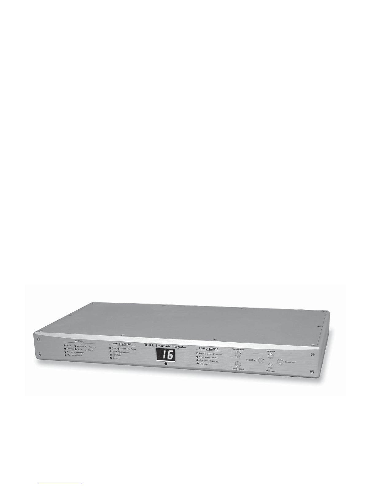
THIEL
SmartSub
™
SI 1 Integrator
Owner Information
Page 2

Page 3

Thank you for purchasing the THIEL SmartSub Integrator. It has been engineered to provide a very high
level of performance and incorporates innovative patented concepts in its design to solve the integration and
balance problems subwoofer systems usually exhibit.
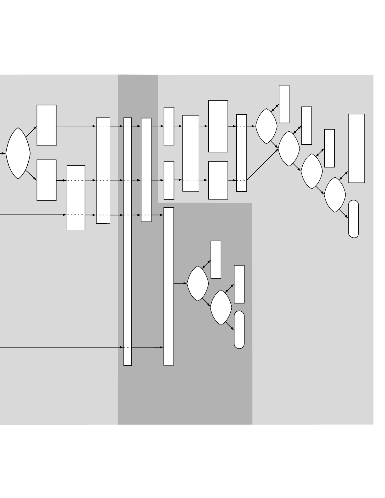
In addition to the hookup and adjustment instructions contained in this booklet, the Setup and
Adjustment Flow Chart on page 8 may (but doesn’t have to be) used as a reference for all aspects of
SmartSub and Integrator system configuration, hookup and adjustment.
You are welcome to contact our Customer Service department with any questions or for help in setting
up this system. Our contact information is:
Tel: 859-254-9427 Fax: 859-254-0075 E-mail: [email protected]
Contents
Introduction ........................................................................................................................................................ 3
Connecting the Integrator...................................................................................................................................4
Modes of operation ............................................................................................................................................................ 4
Crossover mode connections............................................................................................................................................. 4
Augment mode connections............................................................................................................................................... 4
Speaker Polarity................................................................................................................................................................. 5
Adjusting the Integrator ...................................................................................................................................... 6
Presets ............................................................................................................................................................................... 6
System Parameters............................................................................................................................................................ 6
Main Speaker Parameters ................................................................................................................................................. 7
Performance Parameters ................................................................................................................................................... 7
Setup and Adjustment Flow Chart...................................................................................................................... 8
Integrator Parameters for THIEL Speakers...................................................................................................... 10
Advanced Adjustment Tips............................................................................................................................... 10
Equipment rack mounting ................................................................................................................................ 10
Maintenance..................................................................................................................................................... 11
Remote Control Battery Replacement ..............................................................................................................................11
Remote Control Interference.............................................................................................................................................11
Specifications ................................................................................................................................................... 12
Warranty...........................................................................................................................................................12
Remote Control Command Codes ................................................................................................................... 13
Introduction
The SI 1 SmartSub Integrator provides unprecedented ability to perfectly match any SmartSub with any main speakers,
and provide total system performance that is as well integrated and balanced as a full range speaker. This superior
performance is achieved by innovative circuitry (patent 6,687,379, other patents pending) that automatically calculates the
ideal subwoofer response to perfectly match the characteristics of the main speakers. Therefore, instead of the usual
crossover controls that tell the subwoofer how to perform, the SmartSub Integrator has settings for the characteristics of the
main speakers you are matching, the configuration of your system and the performance you desire. This information is then
used to automatically calculate and implement the ideal subwoofer response. In addition, the unit enables the total system to
operate in either augment or crossover system mode and can control up to 16 subwoofer units in either mono or stereo
configuration.
Page 4
Connecting the Integrator
11
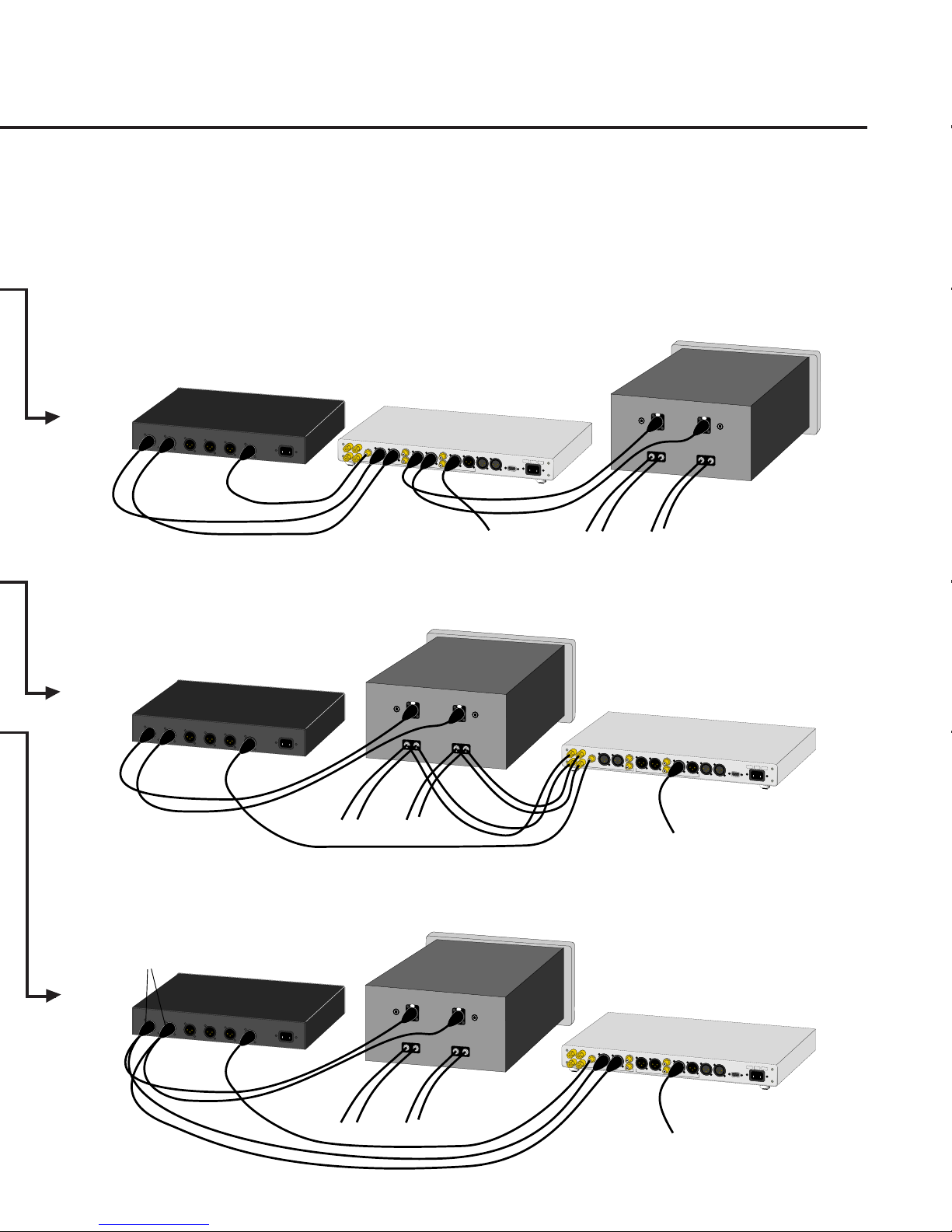
Connect the SmartSub Integrator to the subwoofer
1
11
with an XLR type balanced interconnect cable from the
units’ Sub Output to the subwoofer’s Normal Input. If stereo
subwoofer operation is used, connect one subwoofer from
each channel of the Integrator.
For multiple subwoofers, connect one subwoofer from
the Integrator and daisy-chain the others, with the second
unit connected from the first’s Normal Output, etc. Or, if
two subwoofers are used in mono operation, they can both
be connected to the Integrator using the left and right
outputs.
22
If the system has a surround processor then connect its
2
22
LFE or subwoofer output to the Integrator’s LFE input.
33
3 If you are using a second Integrator or a THIEL
33
passive crossover to derive a subwoofer signal from channels
of your system other than the left/right channels, then
connect the output(s) of that unit to the “Bridge In”
connectors with an XLR type balanced interconnect cable.
Modes of operation
The Integrator has two modes of operation available,
Augment or Crossover, which may use different methods of
connection.
II
f yf y
ou wish tou wish t
I
f y
ou wish t
II
f yf y
ou wish tou wish t
these twthese tw
these tw
these twthese tw
cc
onnections must be used.onnections must be used.
c
onnections must be used.
cc
onnections must be used.onnections must be used.
o modes of opero modes of oper
o modes of oper
o modes of opero modes of oper
AA
ugment modeugment mode
A
ugment mode should be used if you wish to use the
AA
ugment modeugment mode
main speaker normally, receiving the full-spectrum signal,
and are therefore using the subwoofer only to “fill out” and
extend the deep bass response of the main speakers. (In
addition to reproducing the subwoofer channel.)
CC
rr
oo
ssover modessover mode
C
r
o
ssover mode should be used if the main speakers
CC
rr
oo
ssover modessover mode
are not able to play loudly enough or you wish to restrict the
bass energy that the main speakers will reproduce,
transferring this energy to the subwoofer.
o have the abio have the abi
o have the abi
o have the abio have the abi
ation, then cration, then cr
ation, then cr
ation, then cration, then cr
ll
ity tity t
l
ity t
ll
ity tity t
o swito swit
o swit
o swito swit
oo
ssover modessover mode
o
ssover mode
oo
ssover modessover mode
ch betwch betw
ch betw
ch betwch betw
eeneen
een
eeneen
Crossover mode connections
This connection method can be used for operation in
either Crossover and Augment mode.
44
Connect the preamp/processor left/right outputs to the
4
44
Integrator inputs.
55
5 Connect the Integrator outputs to the power amplifier
55
inputs.
Either balanced or unbalance connections can be used
depending on which type of connections are available from
the preamp/processor and to the amplifier.
Augment mode connections
In this case the main speaker system hookup is left as-is,
with no changes. The Integrator can receive its input either
from the output of the power amplifier (speaker level) or
from the output of the preamp/processor (line level).
To implement the speaker level input connection
method:
44
4 Connect cables from the power amplifier output
44
terminals to the respective speaker level input terminals on
the Integrator. Connect the positive amplifier outputs to the
positive Integrator inputs. The cables used for these
connections can be small since no power is being transferred.
Remove the shorting pins when these connectors are used.
To implement the line level input connection method:
44
4 Connect the preamp/processor’s left and right channel
44
outputs to the respective inputs of the Integrator using either
unbalanced (regular) or balanced interconnect cables since
the Integrator will accept either.
This input connection method can only be implemented
if either the preamp/processor has two sets of such outputs
(since one set is already used for connection to the main
amplifier inputs), or if a “Y” connector is used to split the
output into two cables.
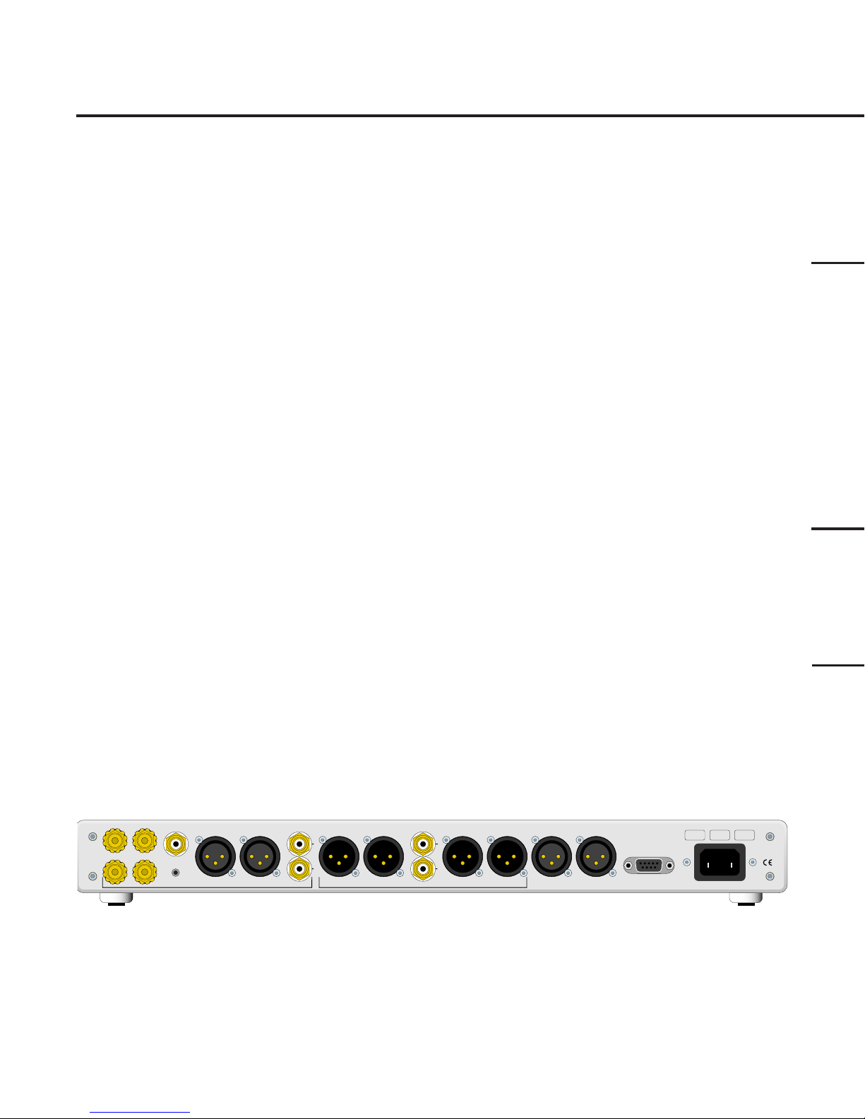
SmartSub Integrator rear connections
Speaker level Inputs
+
L
R
–
Spkr Pol test
INPUTS OUTPUTS
These speaker
level inputs may
be used for
operation in
Augment mode.
Wires to these
terminals are
connected from
the main speaker
power amplifier.
4
This is
used to
receive
the LFE
signal
from the
processor.
Pressing
this
button
checks
speaker
polarity.
For Crossover
mode either
these or the
unbalanced
inputs must be
used to receive
input from the
processor or
preamp. For
Augment mode
operation they
are an alternative
to the speaker
level inputs.
Unbal InputRight Bal InputLeft Bal InputLFE Input Right Bal OutputLeft Bal Output
These
are an
unbalanced
alternative to
the
balanced
inputs.
L
R
For crossover
mode
connection
these or the
unbalanced
outputs are
used to supply
the Integrator’s
output to the
main speaker
amplifier’s
inputs.
Unbal Output Right Sub Output
Left Sub Output Right Bridge In
L
R
These
These connectors
are an
are used to
unbal-
supply signal to
anced
the subwoofer
alterna-
unit(s).
tive to
the
balanced
outputs.
Left Bridge In
THIEL Audio • Lexington, Kentucky USA • www.thielaudio.com • U.S. Patent No. 6,687,379 other patents pending
These connectors
are used to add
the output from
another Integrator
or a passive
crossover into the
Subwoofer signal.
Remote
This
connector
is used to
remotely
control the
unit as an
alternative
to a handheld
remote
control.
Power
S/N
The AC
power cord
connects
here.
Model
SI 1
Page 5
Speaker Polarity
It is necessary that your main speakers be wired in
correct polarity. Since some speakers and amplifiers reverse
the signal polarity, the Integrator includes a test button to
determine if your speakers are connected correctly.
Crossover mode
LEFT
RIGHT
Left/Right
outputs
Preamp or Processor
CENTER
L REAR
R REAR
SUB
Sub
output
S
peak
er
l
ev
e
l
Inp
uts
LF
E
Input
Le
ft Bal
In
put
L +
R
+
L –
R
–
IN
P
U
T
S
SmartSub Integrator
i
ght Bal
Input
U
n
bal
InputR
Left Bal
O
utput
R
i
ght Ba
l
O
utput
L
R
O
U
T
PUTS
U
nbal
With the Integrator left/right outputs connected to the
main speaker power amplifier and the Integrator set to
Augment mode, pushing the “Spkr pol test” button on the
rear of the Integrator should cause the woofers to move
outward. If they move inward, you must reverse the + and –
wires connected to each speaker.
Power Amplifier
for main speakers
L
e
f
t
Bal
I
nput
R
i
ght
B
al
I
nput
IN
P
U
T
L +
O
u
tp
ut
L
eft
S
ub
O
u
t
put
R
i
g
ht Su
b
O
u
tput
L
eft B
r
i
dg
e
In
R
i
ght Br
i
d
ge
L
R
In
R
em
ote
S
/
N
Po
wer
M
odel
T
H
IEL
A
udi
o
Lex
i
ngton, Kentuc
SI 1
k
y
U
SA
w
w
w
.thiel
a
udi
o.com
L –
R
–
R
+
O
U
TPU
T
LEFT
RIGHT
Left/Right
outputs
“Y”
connectors
Preamp or Processor
CENTER
L REAR
R REAR
SUB
Sub
output
Preamp or Processor
To Subwoofer
To main loudspeakers
Augment mode, speaker level input
Power Amplifier
for main speakers
Le
f
t
Bal
I
nput
R
i
gh
t
Bal
I
npu
t
IN
P
U
T
L +
L –
R
–
R
+
O
U
TPU
T
Speak
er
l
evel
Inputs
L +
L –
To main loudspeakers
Augment mode, line level input
Power Amplifier
for main speakers
SmartSub Integrator
E Input
ft Bal
InputLF
R
i
ght Bal
InputLe
U
nbal
Input
Output
R
i
ght Bal OutputLeft Bal
U
R
+
R
–
IN
PUTS
nbal
O
utp
ut
Left
Sub O
ut
L
R
put
R
i
ght Sub Output
Left Br
i
dge In
R
i
ght Br
i
L
R
O
U
T
PUTS
dge In
R
em
ote
S/N
Power
M
odel
T
H
IEL Audi
o
Lex
i
ngton, Kentuck
SI 1
y
U
SA
w
w
w
.thiel
audio.com
To Subwoofer
LEFT
RIGHT
CENTER
L REAR
R REAR
SUB
Left/Right
outputs
Sub
output
L
e
f
t
Bal
I
nput
IN
L +
L –
O
U
To main loudspeakers
R
i
gh
t
B
al
I
npu
t
P
U
T
R
–
R
+
TPU
T
S
peak
er
l
ev
el
Inputs
E
Input
ft Bal
InputLF
R
i
ght Bal InputLe
L +
R
+
L –
R
–
IN
P
U
T
S
SmartSub Integrator
U
nbal
Input
O
utput
R
i
ght Bal OutputLeft Bal
U
nbal
O
utp
ut
Left
L
L
R
R
O
U
T
PUTS
Sub O
ut
put
R
i
ght Sub O
utput
Left Br
i
dge In
R
i
ght B
r
idge In
R
em
ote
S/N
P
ower
M
odel
T
H
IEL Audi
o
Lex
i
ngton, Kentuc
SI 1
k
y
U
S
A
w
w
w
.thiel
audio.com
To Subwoofer
5
Page 6
S
Adjusting the Integrator
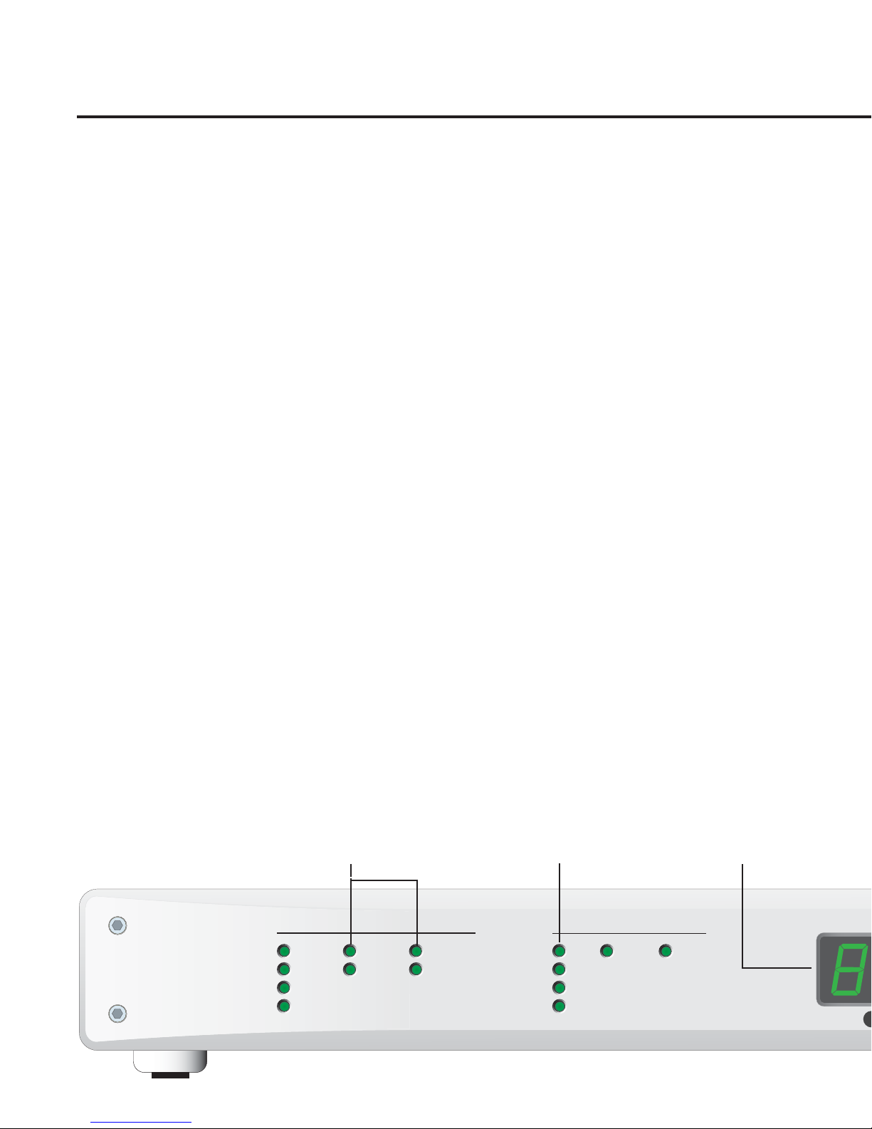
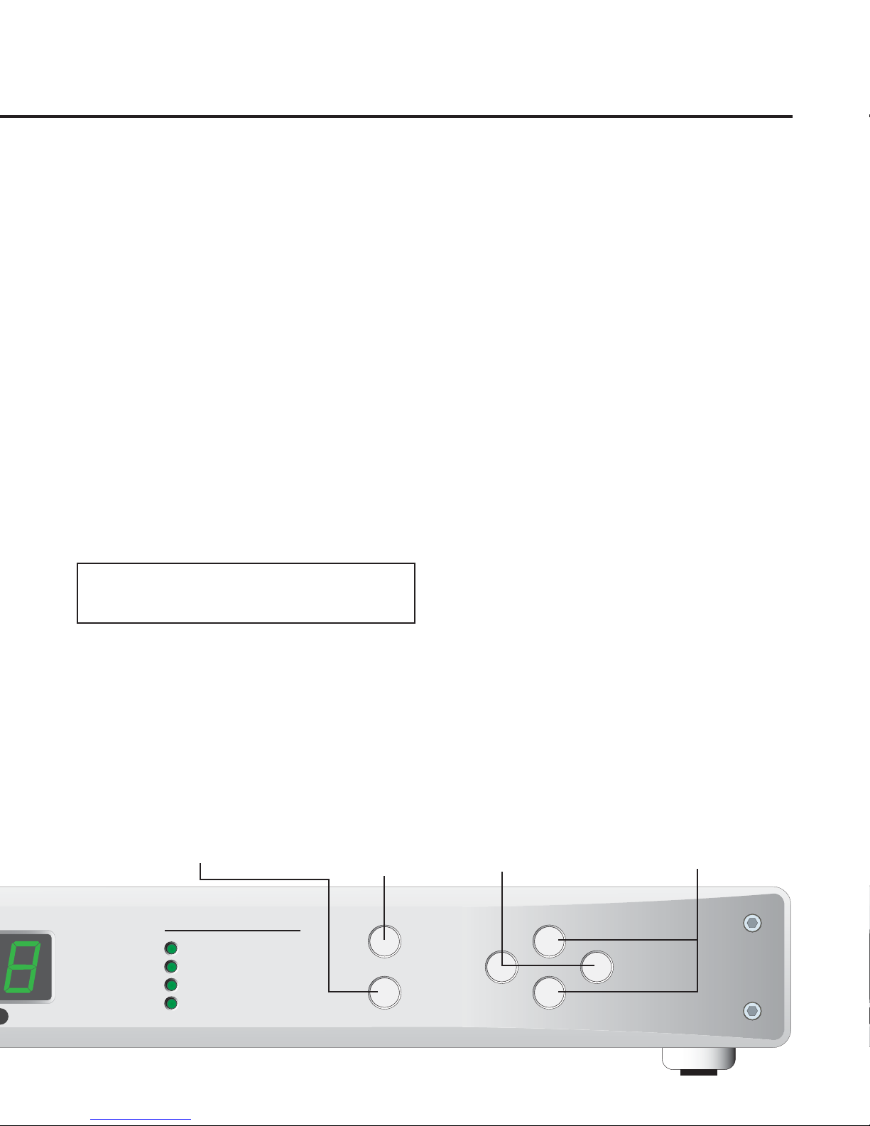
The SmartSub Integrator is adjusted using the four
buttons at the right side of the front panel. All adjustments
are made by first selecting which of the 12 parameters is to
be adjusted and then by increasing or decreasing the setting
of that parameter. A parameter is selected by pressing the
Select Prev or Select Next button until the light for the desired
parameter is on. Once the desired parameter is selected, the
current setting will be shown in the numerical display and
pressing the Increase or Decrease buttons will change the
setting. The parameters Mode, Channels and Type do not
have associated numerical settings and therefore when one of
these is selected the display will be blank. These parameters
instead each have two alternate options that can be selected
by the Increase or Decrease buttons and the current setting is
indicated by which option is lighted.
Only the four performance settings (or three if Augment
mode is used) should be considered adjustments for taste and
requirements. The other parameters should be considered
setup adjustments that are not changed unless there are
changes to the main speakers or the system configuration.
Presets
There are six presets available, each of which stores the
setting of all 12 parameters. The presets can be stored or
recalled from the front panel.
To create a preset, first set all 12 parameters to the
settings you wish to be saved. Pressing the Store Preset button
will cause the display to flash “P1”. Use the Increase and
Decrease buttons to select which preset, from P1 to P6, in
which you wish to store the current settings and then press
the Store Preset button again to complete the save. The
display will stop flashing.
Pressing the Recall Preset button will cause the display to
flash “P1”. Use the Increase and Decrease buttons to select
which preset, from P1 to P6, you wish to recall and then
press the Recall Preset button again to complete the recall.
The display will stop flashing.
If you don’t press the store or recall
button the second time within 10
seconds, the store or recall will be
aborted and the display will revert to
what it was before the button was
pressed.
These lights show the current
setting of the Mode, Channels and
Type parameters which do not
have numerical settings.
System Parameters
Mode [Augment or Crossover]
Augment mode should be used if the main speakers are
able to play loudly enough and the subwoofer is needed only
to extend the bass range. With this mode the signal to the
main speakers will not be altered by the Integrator.
Crossover mode should be used if the main speakers are
not able to play loudly enough or it is desired to limit their
bass extension. In this mode the subwoofer will reproduce
the bass that would normally go to the main speakers.
Channels [Mono or Stereo]
If only one subwoofer unit is used then Mono must be
selected. If more than one subwoofer is used then Stereo may
be selected (but does not have to be). Stereo allows the bass
range of the left and right channels to remain separate and
therefore can provide better left/right “imaging”.
Number of Subwoofers [1 to 16]
This must be set for the total number of subwoofers in
the system. If Stereo Channels is selected then only even
numbers are available. Stereo configurations must use the
same number of subwoofers in each channel.
Main amplifier gain [in dB, 20 to 40]
The setting is the amplification of the main amplifier in
dB (decibels). The number can probably be found from the
owner information or the manufacturer of the amplifier.
This does not need to be set if the only inputs used are
speaker level (when not using the LFE, Bal or Unbal inputs).
These identification lights are
lighted if the parameter is the
one currently selected to be
displayed and adjusted.
This display show the current
setting of the selected
parameter or which preset is
currently being used.
6
SYSTEM
Mode
Channels
Number of Subwoofers
MAIN SPEAKERS
Type
StereoMono
Low Frequency Limit
Sensitivity
DampingMain Amplifier Gain
ReflexSealedCrossoverAugment
THIEL
Smart
Page 7
Main Speaker Parameters
Type [Sealed or Reflex]
Sealed should be selected if the main speakers are a sealed
or “closed” design. Reflex should be selected if the main
speakers are a ported or passive radiator design.
Low Frequency Limit [in Hz, from 20 to 90]
This parameter should be set to the main speaker’s
“minus 3 dB” bass extension specification. This can usually
be obtained from the speaker’s owner information or from
the manufacturer.
Sensitivity [in dB from 83 to 95]
This parameter should be set to the main speaker’s
sensitivity (or “efficiency”) specification (output level in dB
with a 2.83 volt or 1 watt input and at a 1 meter distance).
This can usually be obtained from the speaker’s owner
information or from the manufacturer.
Damping [from .5 to .9]
This parameter should be set to the main speaker’s “Q”
specification. It is not a critical setting and excellent results
can be obtained by using a setting of .8 for sealed speakers
and .7 for reflex speakers.
Visit www.thielaudio.com\subsetup.cfm for
information about parameter settings for most speakers,
regardless of brand.
Performance Parameters
Low Frequency Extension [-3 dB frequency in Hz, 15 to
40]
In Augment mode only settings at least 5 less than the
Low Frequency Limit setting are available.
This setting determines how extended the left and right
channel bass reproduction will be. The lower the number the
more complete the reproduction will be. However, a very low
number will place somewhat more demand on the subwoofer.
The louder you play and the larger the room the harder it is
for the subwoofer. If the subwoofer cannot play loudly
enough you can either increase this number (to 30 or 35) or
add more subwoofer units to your system.
Low Frequency Level [boost or cut in dB, -6 to +6]
This setting controls how much extra left and right
channel bass will be produced by the main speaker/
subwoofer system. Normally it should be set to zero. It
provides increased or decreased bass energy, in the range
below 80 Hz when in crossover mode, and below the main
speaker’s low frequency limit when in augment mode.
Crossover Frequency [in Hz, 40 to 99]
This parameter is only available if Crossover Mode is
selected. Only settings above the Low Frequency Limit
setting by 10 to 30Hz, depending on speaker type and
damping, are available.
This setting determines the frequency below which
energy is directed away from the main speakers and to the
subwoofer. Unless the main speakers are very small, it is
usually preferable that this setting not be higher than 80.
Lower settings will usually provide better sonic results but
will also place more demands on the main speaker to
reproduce bass.
LFE Level [in dB, 0 to 10]
This setting determines the loudness level of the special
effects channel information. Zero is normal, higher numbers
increase the level.
To store a set of parameter settings
first press this button, select which
number to use with the Increase and
Decrease buttons, and then press
this button again.
ub Integrator
PERFORMANCE
Low Frequency Extension
Low Frequency Level
Crossover Frequency
LFE Level
To recall a previously stored set of
parameter settings first press this
button, select which preset using
the Increase and Decrease
buttons, and then press again.
Recall Preset
Store Preset
Select Prev
Use these two
buttons to select
which parameter
you can adjust.
Increase
Decrease
Use these two buttons
to increase or decrease
the setting of the
selected parameter.
Select Next
7
Page 8
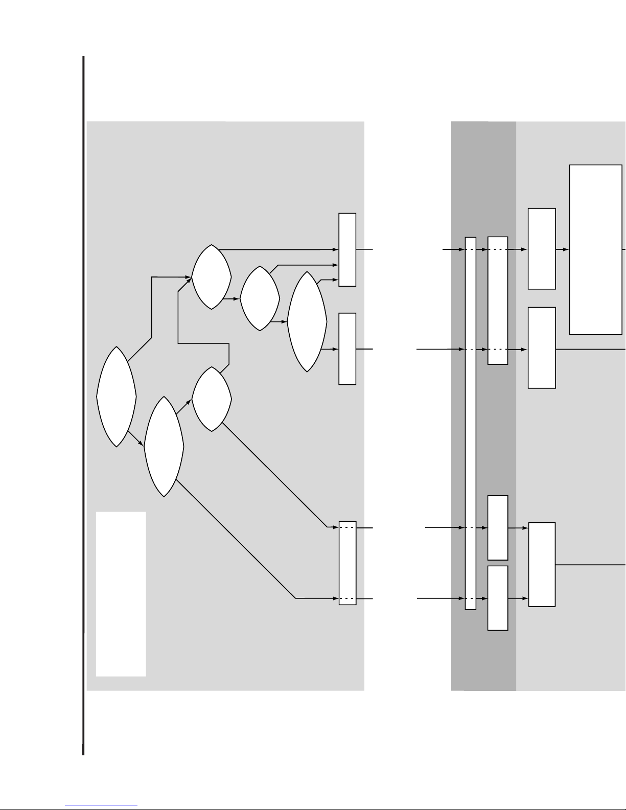
Crossover not required
Do main
speakers produce bass deep
enough and play loudly
enough?
Connect processor’s
subwoofer output to
subwoofer LFE input
Is poor sonic
match of subwoofer
acceptable?
Tell processor main
speakers are “small”
Tell processor main
speakers are “large”
Crossover
decision
Processor
Setup
Y
Y
N
Does your
system have a multi-channel
processor with a subwoofer
output?
Y
N
N
Hookup
Is a passive
crossover available for your
model of THIEL main
speakers?
Use IntegratorUse passive crossover
If you have a processor
tell it main speakers are “large”
Do main
speakers play loudly
enough?
Is correct, fixed
main channel bass
level acceptable?
Y
N
Y
Y
N
N
If you have one, connect
processor's LFE output
to subwoofer LFE input
You can always take the “No” path
but you may take the “Yes” path
if the answer is yes.
Subwoofer will be
used only for
reproduction of
Special effects
channel.
Subwoofer will be
used to reproduce all
low frequency signals
in all channels but
balance and integration
will not be good.
Subwoofer will be
used for effects channel
and enhancing bass of
main channels with very good
blending.
Subwoofer will be
used for effects channel
and main channel bass.
Can provide enhancement
or transfer of bass from
main channels with
excellent blending and
flexible adjustment.
Set subwoofer channel to "On" or "Yes". Set subwoofer level to same as left/right channels
If you have one, connect
processor's LFE output
to Integrator's LFE input
Test the polarity of your amplifier and speakers by
connecting the Integrator's left/right outputs to your main
speaker amplifier inputs, set the Integrator to Augment
mode and push the Spkr Pol Test button on the rear
of the Integrator. If your woofers move inward reverse
the + and – wires connected to each speaker.
Setup and Adjustment Flow Chart
8
Page 9
Connect subwoofer power cord, set On switch, auto on switch, set position controls
Subwoofer
Setup
integrator
Adjustment
Is effects channel
level balanced?
Adjust subwoofer
level
Add subwoofer
Finished
Does
subwoofer play
loudly enough?
Does
subwoofer play
loudly enough?
Listen
Y
N
Y
N
Set Integrator to
Crossover mode
If LFE input not used set subwoofer’s
LFE level control to OFF
Set Integrator to
Augment mode
Set Main speaker amp gain.
Set crossover frequency
as low as it will go.
Set four Main Speaker,
# of subwoofers,
# of channels parameters
Connect additional cables from
main speaker amplifier outputs to
crossover’s speaker level inputs
Connect processor
or preamp outputs
to Integrator inputs
Reconnect processor
or preamp outputs
to main amp inputs
Connect crossover’s or Integrator’s subwoofer
output to subwoofer’s Normal input
YN
If LFE input is used
set main speaker
Amp Gain
Is main
channel bass level
correct?
Adjust Low
Frequency Level
Finished
Increase crossover
frequency
Increase Low Frequency Extension
setting, decrease LFE Level setting
or add subwoofer
Y
N
Is effects
channel correct
loudness?
Adjust LFE Level
Y
N
Y
N
Y
N
Do main
speakers play
loudly enough?
Listen
Do main
speakers play loudly
enough with
demanding bass?
9
Page 10

Integrator Parameters for THIEL Speakers
Visit www.thielaudio.com\subsetup.cfm for information about parameter settings for most speakers, regardless of brand.
Model Type Low Frequency Limit Sensitivity Damping
CS1.6 Reflex 49 90 .7
CS2.4 Reflex 33 87 .7
CS3.6 Reflex 27 86 .7
CS6 Reflex 27 86 .7
CS7.2 Reflex 23 86 .7
MCS1 Reflex 47 90 .7
PCS Reflex 55 87 .7
SCS3 Reflex 46 87 .7
PowerPoint Sealed 75 89 .8
PowerPlane Sealed 75 89 .8
Advanced Adjustment Tips
The accuracy of results achieved in providing a perfect transition between the subwoofer and the main speakers is limited
by the accuracy of the main speaker specifications. If these specification are not accurate, then the results will not be
optimum. Even the use of inaccurate specs will almost always achieve fairly good results but if you feel the results are not
optimum you may experiment with altering the three main speaker parameter settings other than type. The performance
effect of these settings are listed below.
Low Frequency Limit
Increasing this setting will cause more output in the frequency region of the setting and decreasing the setting will cause
less output. For example, if the main speaker -3 dB limit is specified as 50 Hz, then increasing the setting to, say, 53 will cause
somewhat more output in the 50 Hz region.
Sensitivity
Increasing this setting will cause the subwoofer to play louder by the amount of the setting change and decreasing it
causes the subwoofer to play more quietly. For example, increasing the setting one dB will increase the subwoofer's output by
1 dB across its entire bandwidth (which is up to the main speaker's low frequency limit if in augment mode, or up to the
crossover frequency if in crossover mode).
Damping
Increasing this setting will cause LESS output in the region above the speaker's -3 dB limit and decreasing the setting will
cause more output in the region. For example, if the main speaker has specifications of a low frequency limit of 50 Hz and
damping of 0.7, then increasing the damping setting to 0.8 will cause about 1 dB less output in the region from 50 Hz to 100
Hz.
Equipment rack mounting
Included with the Integrator are two Rack Mount “ears” for mounting the unit into a standard 19" equipment rack. To
install these “ears”:
Remove the 4 screws in the unit’s front panel, place the ears so their rear protrusions fit into the front panel’s screw
recesses, and re-install the panel screws through the ear holes.
10
Page 11
Maintenance
Remote Control Battery Replacement
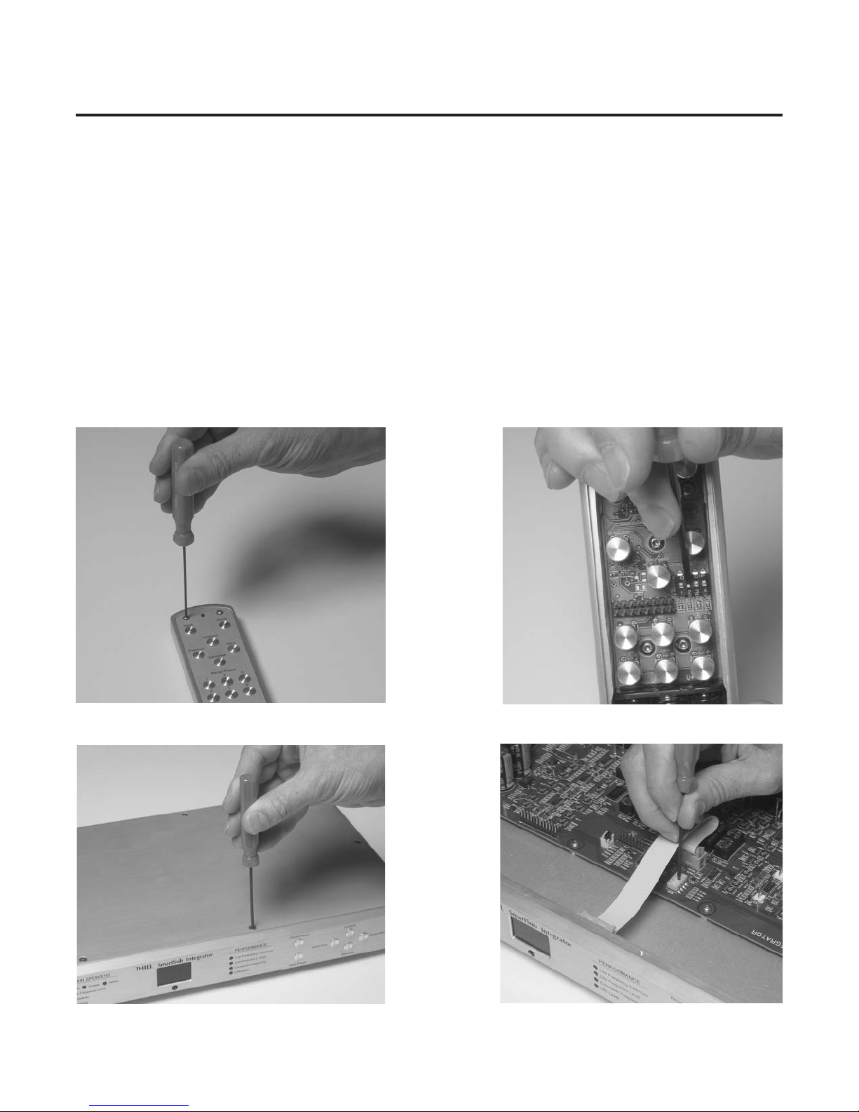
The green light on the front of the Remote Control should light when any of the buttons are pushed. If it does not the
batteries need to be replaced. Access the batteries by removing the four screws on the front of the unit using the hex driver
provided, and lifting off the front cover (see illustration below). Replace the three AAA size batteries, taking care to insert
the new batteries in the proper direction as indicated on the battery holder. The center battery should be positioned with its
small, positive terminal toward the bottom end of the unit, and the other two batteries in the opposite direction. When
replacing the panel some jiggling of the buttons may be required to align them with the holes in the panel.
Remote Control Interference
It is possible that the Integrator’s remote control will also affect other equipment or that the remote control of other
equipment will affect the SmartSub Integrator. In case this happens, the Integrator and its remote are able to operate on any
of 16 channels so that a channel can be selected that does not interfere with other equipment. A different channel is selected
by changing the settings of 4 miniature switches inside both the Integrator and its remote. Removing the top cover of each
piece using the hex driver provided allows access to the switches (see illustrations below). They can be switched to any of the
16 possible combinations but the settings in the remote must be the same as those in the Integrator. Experiment until a
channel is found that is free from interference.
Removing the remote’s panel to access its batteries and
channel selector switches.
Removing the Integrator’s top panel to access its channel
selector switches.
Adjusting the remote’s channel selector switches.
Adjusting the Integrator’s channel selector switches.
11
Page 12

Specifications
Size ................................................................................................................ 17" wide, 1.75" high (2" with feet), 9" deep
Inputs.............................................. Speaker level, Line level balanced and unbalanced, LFE unbalanced, bridging Sub
Main Speaker Outputs.............................................................................................................. Balanced and unbalanced
Subwoofer Output ............................................................................................................................................... Balanced
Line Voltage.......................................................................................................................................... 90-130 or 180-260
Warranty
THIEL warrants every THIEL model SI1 system against defects in materials and workmanship to the original owner for a
period of ten years from the date of purchase. THIEL will, at no charge, replace any defective part and make any repairs
necessary to ensure its proper performance when the defective unit is returned to us postpaid.
This warranty does not cover damage due to accident or abuse and is void if the unit has been tampered with.
12
Page 13

Remote Control Command Codes
n
This information is provided for developers of automated systems. It is not relevant to most users.
Function Allowed RS-232 code * RC5 code (Dec)
values (## = values) Command **
Next SS00NT 10
Previous SS00PV 11
Increase SS00IC 12
Decrease SS00DC 13
Store# 0-6 ‡ SS##SO 14+#
Recall# 0-6 ‡ SS##RL 21+#
Augment SS00AG 28
Crossover SS00XO 29
Mono SS00MN 30
Stereo SS00SE 31
#subs 1-16 SS##NU 31+#
Amp gain 20-40 SS##AN 48 §
Sealed SS00SD 49
Reflex SS00RX 50
LF limit 20-90 SS##LT 51 §
Sens 83-95 SS##SN 52 §
Damping 5-9 † SS##DM 48+#
LF ext 15-40 SS##ET 58 §
LF level 0-12 †† SS##LL 59 §
XO Freq 40-99 SS##XF 60 §
LFE level 0-10 SS##LE 61 §
Digit 0-9 0-9
* RS-232 port protocols are: 38,400 Baud, 8 data bits, 1 stop bit, no parity.
‡ Values of 1 to 6 execute a direct store or recall to that memory.
A value of 0 initiates the command. For completion, increase or decrease
commands select which memory, and a second store or recall completes the command.
† Multiply desired setting by 10. Example: setting of 0.7 = value of 7.
†† Add 6 to the desired LF setting. Example: setting of zero = value of 6.
§ These commands must be followed by two digit commands or the sequence is aborted.
** RC5 system value depends on DIP switch settings:
Switch settings System DIP switch settings must be the same in the Integrator and the Remote control u
on-on-on-on 7 The DIP switches are accessed by removing the top cover of each unit.
on-on-on-off 11
on-on-off-on 14
on-on-off-off 15
on-off-on-on 17
on-off-on-off 18
on-off-off-on 19 The RC5 code is a 14 bit word that is built with
on-off-off-off 20 a start bit of “1”, a second bit of “0”,
off-on-on-on 21 a toggle bit that changes with each new key press,
off-on-on-off 22 5 “system” bits and then 6 “command” bits.
off-on-off-on 23 In decimal notation, this is 16,384, plus 64 times
off-on-off-off 24 the system value, plus the command value,
off-off-on-on 25 with 4096 added to each alternate key press.
off-off-on-off 26
off-off-off-on 27
off-off-off-off 28
System*
RC5 code (Dec)
Command
st
1
nd3rd
2
1
EXAMPLES
Function RS-232 code
Recall preset 4 SS04RL 25 25 4659 – –
Set XO Freq to 65 SS65XF 25 60 6 5 467C 4646 4645
Set LF Level to +3 SS09LL 25 59 0 9 467B 4640 4649
RC5 word (hex)**
st
nd
2
rd
3
* If DIP switches set to off-off-on-on. ** Assuming toggle bit = 0.
13
Page 14

Page 15

Page 16

Tel: 859-254-9427 • Fax: 859-254-0075 • Email: [email protected] • www.thielaudio.com
THIEL
1026 Nandino Blvd., Lexington, KY 40511
7/05
 Loading...