

Page 1
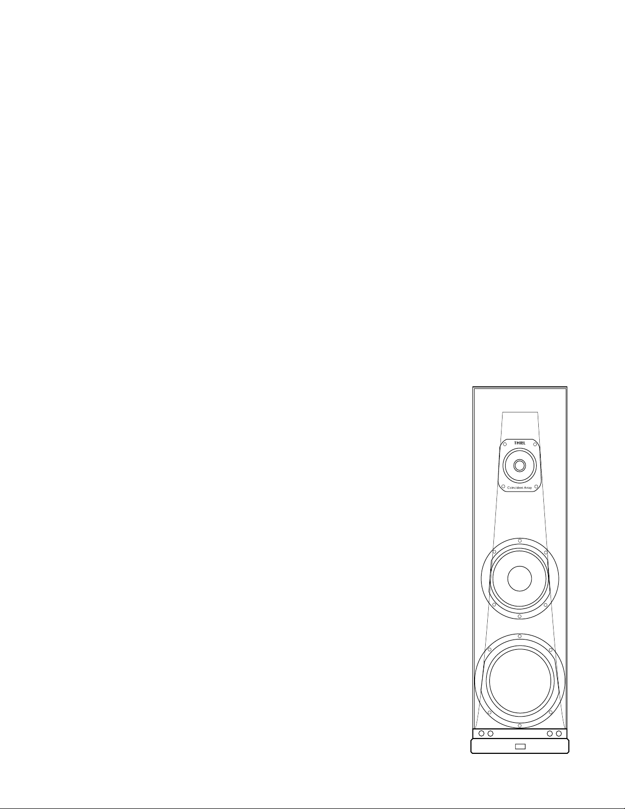
Technical Information
THIEL CS6
Coherent Source
®
Loudspeaker
This paper describes some of the technical performance aspects, design
considerations and features of the THIEL model CS6 loudspeaker system. It is
intended to supply information for those who are interested in such matters. It is not
intended to imply that good measured technical performance is sufficient to
guarantee good sonic performance.
THIEL • 1026 Nandino Boulevard • Lexington, Kentucky 40511 • USA
Telephone: 859-254-9427 • Fax: 859-254-0075 • E-mail: [email protected]
Web: www.thielaudio.com 5/00
Page 2

THIEL DESIGN PHILOSOPHY
All THIEL speakers are intended to be precision instruments that very accurately translate electronic information into musical sound.
All our efforts have been directed toward achieving extremely faithful translation of all tonal, spatial, transient and dynamic information
supplied by the amplifier. THIEL speakers are not intended to mask or mitigate shortcomings of the recording or other components in the
music playback system. We believe this approach is the only way to provide the potential of experiencing all the subtle aspects that help
make reproduced music a most enjoyable human experience.
Performance goals
Since quality of musical performance is a very complex issue it is helpful to objectively identify the aspects involved. We believe
musical performance can be described, with not much oversimplification, as performance in four areas.
Tonal fidelity includes overall octave-to-octave balance, the fidelity of timbres, absence of vowel-like colorations, and bass
extension.
Spatial fidelity includes how wide and deep the performing space seems, how convincingly instruments are placed from the center to
beyond the speakers laterally, how realistic the depth perspective is, how little the speakers’ positions seem to be the source of the sound,
and how large the listening area is.
Transient fidelity includes how clearly and cleanly musically subtle low–level information is reproduced and how convincingly
realistic is the reproduction of the initial or ‘attack’ portions of sounds.
Dynamic fidelity includes how well the speaker maintains the contrasts between loud and soft and how unstrained and effortless is
the reproduction of loud passages.
Fundamental design considerations
In our opinion, natural spatial reproduction requires creating a realistic sound field within the listening room by mimicking the
properties of natural sound sources. These properties include wide area radiation and the absence of out-of-phase energy. To meet these
requirements all THIEL speakers employs dynamic drivers. Dynamic drivers have the advantages of providing a point source radiation
pattern with good dispersion of sound over a wide area, great dynamic capability, good bass capability, and a lack of rearward out-ofphase energy. Another advantage of dynamic drivers is that their small size allows the multiple drivers to be arranged in one vertical line.
This alignment avoids the problem of side-by-side driver placement which causes the distances from each driver to the listener to change
with different listener positions.
The major potential disadvantages of dynamic speakers are diaphragm resonances (“cone breakup”), cabinet resonances and cabinet
diffraction. Also, they share with other types of speakers the potential problems of time and phase errors introduced by multiple drivers
and their crossovers. None of these problems is a fundamental limit and all can be minimized or eliminated by thorough and innovative
engineering, allowing the possibility of a speaker system without significant fundamental limitations.
Technical requirements
The task of engineering a speaker system requires the translation of the musical performance goals into technical goals. Although
there are also many minor design considerations, the following are what we believe to be the major technical requirements that contribute
to each of the musical goals.
Tonal fidelity:
• Accurate frequency response so as to not over or under emphasize any portion of the sound spectrum
• Absence of resonances in the drivers or cabinet so as not to introduce tonal colorations
Spatial fidelity:
• Point-source, unipolar radiation
• Time response accuracy to preserve natural spatial cues
• Lack of cabinet diffraction
• Even dispersion of energy of all frequencies over a wide area
Transient fidelity:
• Phase coherence to provide realistic reproduction of attack transients
• Very low energy storage to provide clarity of musical detail
Dynamic fidelity:
• High output capability
• Low distortion
Design goals
The technical requirements result in the following major technical design goals:
1. Very uniform frequency response
2. Time response accuracy
3. Phase response accuracy
4. Low energy storage
5. Low distortion
1
Page 3

THIEL CS6 SPECIFICATIONS
Bandwidth (-3 dB)
Amplitude response
Phase response
Sensitivity
Impedance
Recommended Power
Size (W x D x H)
Weight
29 Hz - 18 KHz ±2 dB
13 x 18.5 x 50 inches
27 Hz - 34 KHz
minimum ±10°
86 dB @ 2.8 v-1m
4Ω, 2.4Ω minimum
100-500 watts
175 lb
Driver Complement:
Woofer
10" (8.2" radiating area) with anodized aluminum cone, cast
frame, 2" dia voice coil. Underhung coil (short coil/ long gap) motor
system. Linear travel 5/8" pk-pk, 36 in3 linear displacement. 10 lb
magnet, 20 lb total magnet structure. Copper pole sleeve, copper
magnet ring. Made by THIEL.
Midrange
5" (4.1" radiating area) with 3 layer anodized aluminum/
polystyrene/aluminum diaphragm, cast frame, 11/2" dia voice coil.
Underhung coil (short coil/long gap) motor system. Linear travel 1/8"
pk-pk. Two magnets with total weight of 5 lb power midrange and
tweeter. Copper pole sleeve. Made by THIEL.
Tweeter
1" (1.2" radiating area) with anodized aluminum dome.
Underhung coil (short coil/long gap) motor system. Linear travel 3/16"
pk-pk. Copper pole sleeve. Ferrofluid. Made by THIEL.
2
Page 4
FREQUENCY RESPONSE
Since frequency response errors are a measure of tonal imbalances which alter music’s tonal characteristics, we believe that accurate
frequency response is an absolute requirement for a truly good speaker. Our design goal for the CS6 was to achieve accuracy in the
design prototype of ±1 dB and a production tolerance of ±1 dB. The result is a tolerance in every production speaker of ±2 dB and a
tolerance from speaker to speaker of ±2 dB at all frequencies.
In our opinion the human ear is sensitive enough to the balance between component harmonics of musical sounds to detect frequency
balance errors of as little as 0.2 dB if they are over a range of an octave or more. Therefore, even more important than the maximum
amount of response error at any frequency is the octave averaged, octave-to-octave balance which has a very high correlation with
perceived tonal balance. Our design goal was to achieve octave-averaged response within ±0.5 dB from 50 Hz to 15 KHz. Any deviation
more than .5 dB is confined to only a narrow frequency range and therefore will have less effect on the perceived balance.
Achieving these goals requires the use of drivers with very uniform responses, reduction of usual cabinet diffraction which causes
response errors, and compensation of driver response anomalies in the electrical network.
Driver response
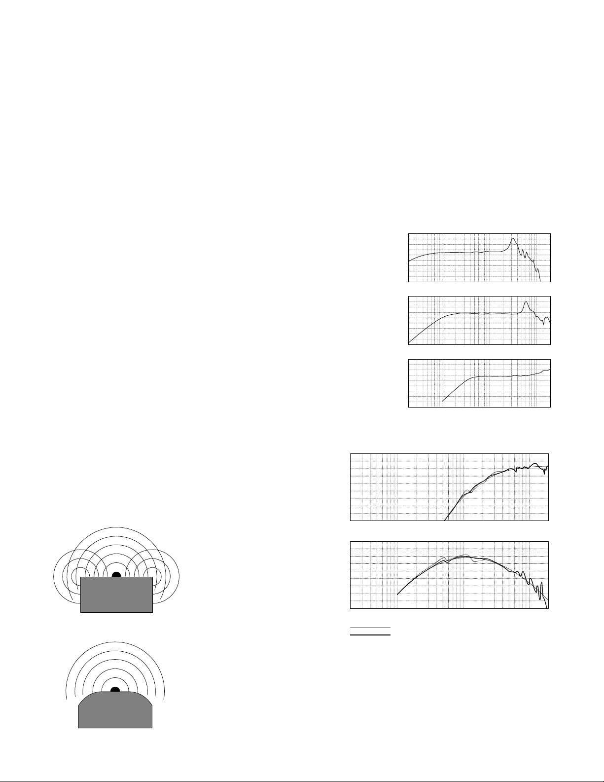
The major cause of nonuniform driver response is diaphragm resonances. These
resonances are also the major energy storage mechanism. In the CS6 all three driver
diaphragms are constructed of anodized aluminum which provides much higher stiffness and
compressive strength than conventional diaphragm materials. The primary benefit is that the
lowest internal resonance is much higher than with other materials. Below this lowest
resonance there are no resonances to store energy and cause ringing. An additional benefit is
that the aluminum’s higher compressive strength results in more of the energy of a transient
attack being transferred to sonic output rather than being absorbed in compression of the
diaphragm material. In the case of the CS6’s tweeter the lowest diaphragm resonance occurs
above the range of hearing at 22 KHz. The lowest diaphragm resonances for the other
drivers are 3 KHz, and 6 KHz, putting them 2.5 and 1 octave above their respective
crossover points of 500 Hz and 3 KHz. So, in every case, each driver has no internal
resonances in its operating range to cause response irregularities and colorations of the
speaker’s tonal response.
Figure 1 shows the frequency response (in an infinite baffle) of the CS6’s drivers. You
will notice that in each case the response is virtually perfect below the primary diaphragm
resonance.
Diffraction
Diffraction causes frequency response and time response errors and
therefore a reduction in tonal, spatial, and transient fidelity. Diffraction
occurs when some of the energy radiated by the drivers is reradiated at a
later time from cabinet edges or other sudden change of environment. For
musical signals that remain constant for a few milliseconds, diffraction
causes, by constructive and destructive interference, an excess of energy to
the listener at some frequencies and a
Cabinet-edge diffraction
deficient amount of energy to the
listener at other frequencies.
Diffraction also causes all transient
signals to be radiated to the listener a
second (and possibly a third) time,
tweeter
smearing transient impact and
distorting spatial cues.
To greatly reduce diffraction the
CS6 employs a baffle that is curved
at the edges so energy radiated along
the baffle can continue into the room
without encountering abrupt edges.
Figure 2 compares the response of
the tweeter and mid drivers in a
conventional square-edged cabinet and in the CS6’s cabinet with the target response. It can be seen
that response imperfections are reduced by approximately 75% in the mid driver’s bandpass and in
the response of the tweeter below 6 KHz.
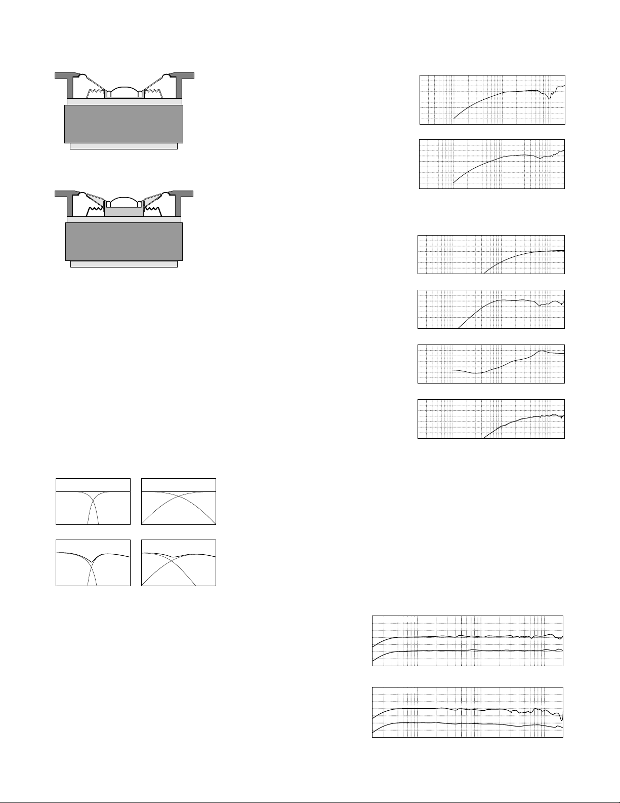
Coaxially mounting the tweeter and mid driver would normally be another source of
diffraction of the tweeter’s energy. The upper diagram on page 4 shows a tweeter mounted in a
normally shaped mid diaphragm. The conical shape of the tweeter’s environment causes response
irregularities shown in the upper graph of Fig. 3. To solve this response problem the CS6 uses a
Figure 2 Target response, response with rounded-edge cabinet and
response with square edge cabinet for tweeter (top) and mid drivers.
90
85
80
Amplitude — dB
90
85
80
Amplitude — dB
.........................
Figure 1 Woofer, midrange and tweeter driver responses
100
90
80
Amplitude — dB
70
10020
100
90
80
Amplitude — dB
70
10020
100
90
80
Amplitude — dB
70
10020
10020
10020
target response
round edge cabinet response
square edge cabinet response
Frequency
Frequency
1K
1K
Frequency
Frequency
Frequency
1K
1K
1K
10K
10K
10K
10K
10K
20K
20K
20K
20K
20K
3
Page 5
10K
Frequency
1K
100
90
80
70
10020
20K
Amplitude — dB
Coaxially mounting of tweeter in normal midrange
10K
Frequency
1K
90
80
70
10020
20K
Amplitude — dB
10K
Frequency
1K
90
80
70
10020
20K
Amplitude — dB
10K
Frequency
1K
0
-10
-20
10020
20K
Amplitude — dB
10K
Frequency
1K
90
80
70
10020
20K
Amplitude — dB
diaphragm
mid diaphragm shaped with a very shallow flare
which provides much improved tweeter response as
illustrated in the lower graph of Fig. 3. However,
this shallow diaphragm shape would cause poor
response of the mid driver and so the CS6 utilizes a
3-layer diaphragm that provides the shape required
for the tweeter while providing a very strong
structure for the mid diaphragm. The 3-layer
sandwich is constructed of a cast polystyrene
central core laminated with anodized aluminum on
Coaxially mounting of tweeter in CS6 midrange
diaphragm
both surfaces.
Network correction
The last method for achieving accurate
frequency response is to include electrical
correction of response irregularities. The CS6
makes extensive use of network compensation. 12
of the 32 network elements are used to achieve
correction of what would otherwise be minor
response irregularities in the complete speaker
system.
As an example, figure 4 illustrates, for the tweeter, the target response, driver (in
cabinet) response, the network response and the final acoustic response (which is the sum of
the driver and network responses). As can be seen, the actual response matches the target
response very closely. Without the inclusion of 7 additional network elements the response
would be much less ideal. Notice in the network response the non-simple shape of the curve;
for example, the depression around 4000 Hz and the strong response near 7 KHz.
Figure 3 Response of tweeter in conical mid
diaphragm and in CS6 mid diaphragm
100
90
80
Amplitude — dB
70
10020
Frequency
1K
Figure 4 Tweeter’s target, driver (in cabinet),
network, and resulting response.
10K
20K
Off-axis response
In addition to on-axis response accuracy, it is also important that the off-axis response
be properly balanced, without major dips, for two reasons. First, listeners may be located far
from the optimum position and therefore will be hearing the speaker as it performs off-axis.
Secondly, off-axis response is a measure of how uniform the total energy response of the
speaker is. Since the total energy (in all directions) radiated from the loudspeaker
determines the amount of reverberant energy in the room, it is important that the off-axis
response be uniform to avoid changes in perceived character and spatiality at different
High-slope system on-axis First-order system on-axis
High-slope system off-axis
First-order system off-axis
The end result of reducing diffraction, reducing diaphragm resonances and
correcting response anomalies in the network is a speaker with very accurate
tonal characteristics. The upper graph of figure 5 shows the on-axis frequency
response of the CS6. It is uniform within ±1.5 dB from 29 Hz to 18 KHz.
Subjectively even more important is the octave-averaged frequency response,
shown offset 10 dB. The graph shows this response to be within ±0.5 dB from
45 Hz to 15 KHz which indicates extremely accurate overall tonal balance.
Furthermore, as a result of gradual crossover slopes, the off-axis frequency
response of the speaker system is also smooth and well balanced. This unusual
performance is important for producing a uniform amount of ambient energy at
all frequencies, necessary for natural spatial reproduction. The lower graph
shows the 30° off-axis response to be within ±2.0 dB from 30 Hz to 13 KHz,
showing very uniform dispersion of energy at all frequencies.
frequencies.
Most speakers with high-slope crossover systems cannot maintain uniform off-axis
response because the dispersion of a driver narrows as frequency increases toward the
crossover frequency. Above the crossover frequency the radiation of the next driver is
again wide since it is operating at the low end of its range. First order crossover systems
have an advantage in this regard. Since a significant part of the total energy below the
crossover point is radiated by the upper driver, the narrowing of the dispersion of the
lower driver has much less effect on the total output. Speakers with first-order crossover
systems, like the CS6, therefore, usually have a more uniform off-axis response and
much more uniform total power response.
Results
90
80
Amplitude — dB
70
90
80
Amplitude — dB
70
Figure 5 Normal and octave-averaged frequency
response on-axis and 30° off-axis.
on axis
10020
30° off axis
10020
Frequency
Frequency
1K
1K
20K
10K
20K
10K
4
Page 6
TIME RESPONSE
In most loudspeakers the sound from each driver reaches the listener at different times causing the loss of much spatial information.
One problem caused by different arrival times from each driver is that the only dependable locational clue is the relative loudness of
each speaker. Relying only on loudness information causes the sound stage to exist only between the speakers. In contrast to this
loudness type of imaging information, the ear–brain interprets real life sounds by using timing information to locate the position of a
sound. The ear perceives a natural sound as coming from the left mainly because the left ear hears it
Time correction
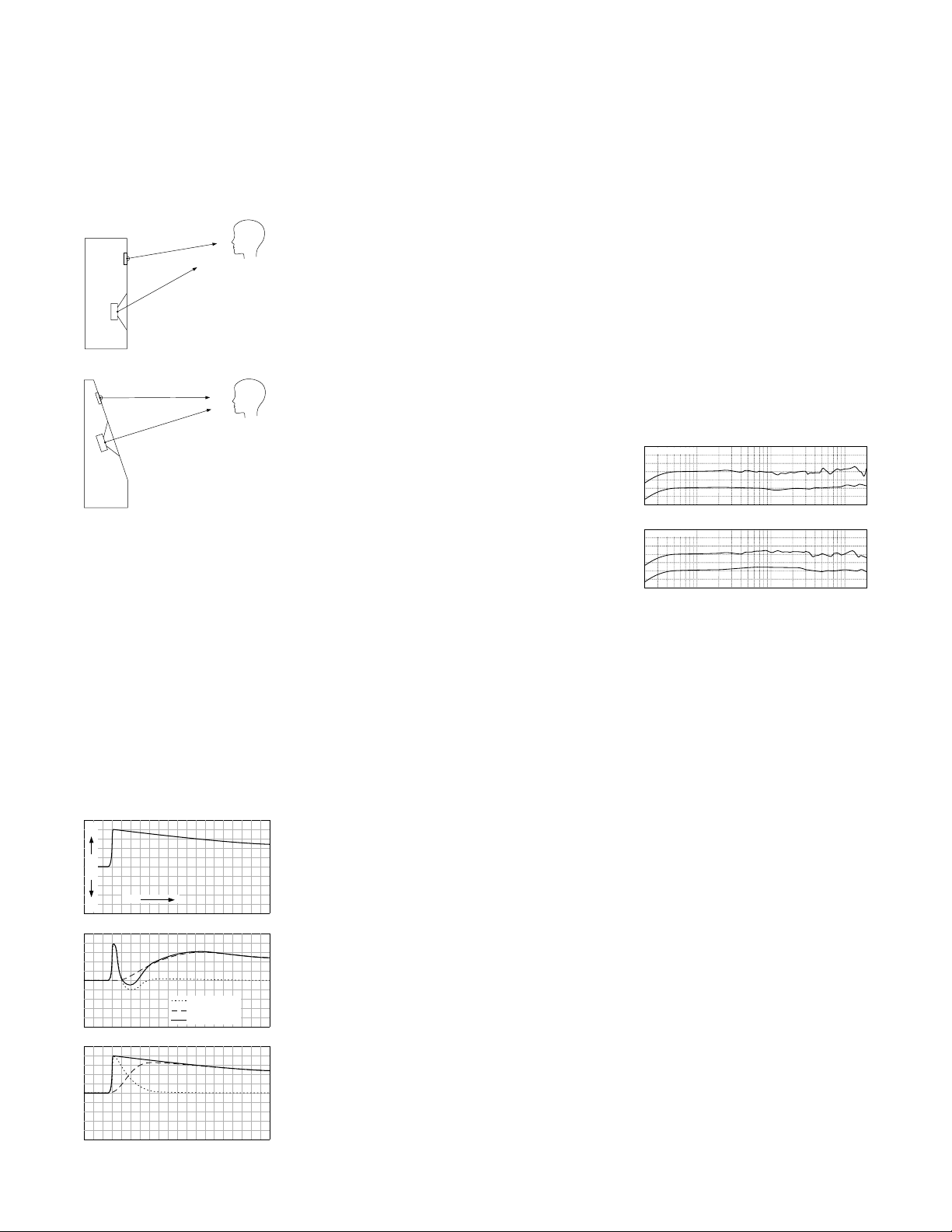
time alignment between these two drivers regardless of listener position. Figure 6 shows
the frequency response 5° above and below the ideal listening axis. At normal listening
distances ±5° represents a listening window height of about 2 feet. Even under these
conditions the response remains very good, particularly in the high frequency range.
first. That it may also sound louder to the left ear is of secondary importance.
Another problem is that for realistic reproduction, it is important that the attack, or start, of every
sound be clearly focused in time. Because more than one driver is involved in the reproduction of the
several harmonics of any single sound, the drivers must be heard in unison to preserve the structure
of the sound. Since, in most speakers, the tweeter is closer to the listener’s ear, the initial attack of
the upper harmonics arrives a millisecond or so before the body of the sound. This delay results in a
noticeable reduction in the realism of the reproduced sound.
To eliminate both these problems the CS6 drivers are mounted on a sloped baffle to position
them so the sound from each reaches the listener at the same time. The sloping baffle arrangement
can work perfectly for only one listening position. However, because the drivers are positioned in a
vertical line the error introduced by a listener to the side of the speaker is very small. Also, because
the driver spacing is not more than the approximate wavelength of the crossover frequency, the error
introduced by changes in listener height are small within the range of normal seated listening heights
provided the listener is 8 feet or more from the
speakers.
In the CS6, the arrival time error caused by nonideal listener height is greatly reduced in the upper part
of the frequency spectrum (where it is most
problematic) by mounting the tweeter coaxially with
the midrange driver. Coaxial mounting ensures perfect
Figure 6 Normal and Octave-averaged frequency response
5° above axis
90
80
70
Amplitude — dB
Frequency
Frequency
1K
1K
5° below axis
90
80
Amplitude — dB
70
10020
10020
20K
10K
20K
10K
PHASE RESPONSE
We use the trade mark Coherent Source to describe the unusual technical performance of time and phase coherence which gives
THIEL products the unusual ability to accurately reproduce musical waveforms.
Usually, phase shifts are introduced by the crossover slopes, which change the musical waveform and result in the loss of spatial and
transient information. The fourth order Linkwitz-Riley crossover is sometimes promoted as being phase coherent. What is actually
meant is that the two drivers are in phase with each other through the crossover region. However, in the crossover region neither driver
is in phase with the input signal nor with the drivers’ output at other frequencies; there is a complete 360° phase rotation at each
crossover point.
Since 1978 THIEL has employed first order (6dB/octave) crossover systems in all our Coherent Source speaker systems. A first
Figure 7 Crossover step response
+
Output
-
Time
Ideal step response
tweeter output
woofer output
Time corrected fourth order crossover system
First order crossover system
combined output
order system is the only type that can achieve perfect phase coherence, no time smear, uniform
frequency response, and uniform power response.
A first order system achieves its perfect (in principle) results by keeping the phase shift of each
roll-off less than 90° so that it can be canceled by the roll-off of the other driver that has an identical
phase shift in the opposite direction. (Phase shifts greater than 90° cannot be canceled.) The phase
shift is kept low by using very gradual (6dB/octave) roll-off slopes which produce a phase lag of 45°
for the low frequency driver and a phase lead of 45° for the high frequency driver at the crossover
point. Because the phase shift of each driver is much less than 90° and is equal and opposite, their
outputs combine to produce a system output with no phase shift and perfect transient response.
Figure 7 graphically demonstrates how the outputs of each driver in a two-way speaker system
combine to produce the system’s output to a step input. The first graph shows the ideal output. The
second shows the operation of a time-corrected, fourth order crossover system. The two drivers
produce their output in the same polarity and both drivers start responding at the same time.
However, since the high-slope network produces a large amount of phase shift, the tweeter’s output
falls too quickly and the woofer’s output increases too gradually. Therefore, the two outputs do not
combine to produce the input step signal well but instead greatly alter the waveform. The third graph
shows how, in a first order crossover system, the outputs of the two drivers combine to reproduce the
input waveform without alteration.
In practice, the proper execution of a first order system requires very high quality, wide
bandwidth drivers and that the impedance and response variations of the drivers and the cabinet be
compensated across a wide range of frequencies. This task is complex since what is necessary is that
the acoustic driver outputs roll off at 6 dB/octave and not simply for the networks themselves to roll
5
Page 7
off at 6 dB/octave. For example, if a typical tweeter with a low frequency roll-off of 12 dB/octave is combined with a 6 dB/octave
Time – msec
0.5 1.0
Output
1.5 2.0 2.5
network, the resulting acoustical output will roll off at 18 dB/octave. Therefore, in practice, the required network circuits are much more
complex than might be thought.
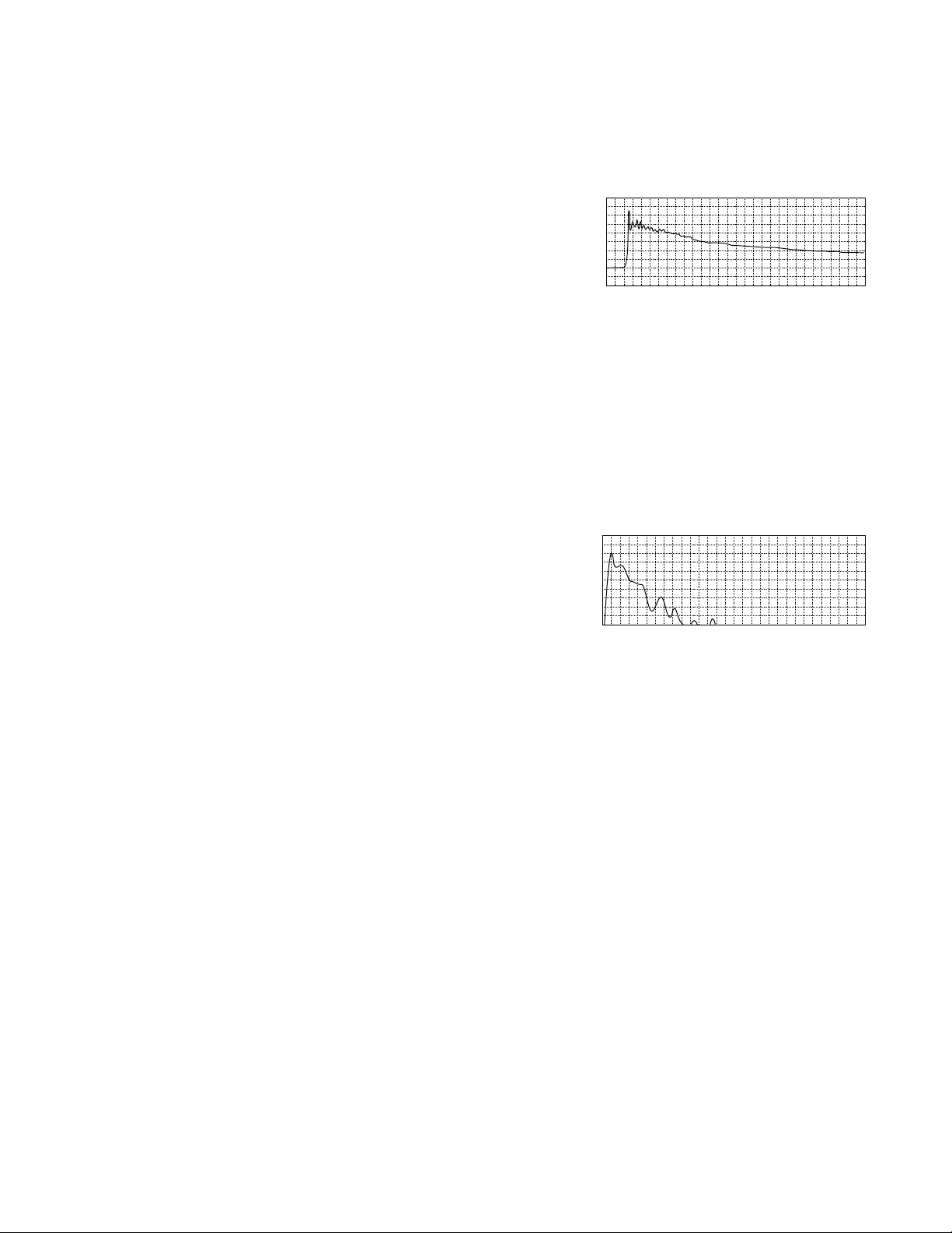
The result of phase coherence (in conjunction with time coherence) is that all waveforms will be reproduced without major
alterations. The speaker’s reproduction of a step waveform best demonstrates this fact
since, like musical waveforms, a step is made up of many frequencies which have
Figure 8 CS6 step response
precise amplitude and phase relationships. For a step signal to be accurately
reproduced, phase, time and amplitude response must all be accurate. Because this
waveform is so valuable, it is commonly used to evaluate the performance of
electronic components. It is not typically used for speaker evaluation because most
speakers are not able to reproduce it recognizably. Figure 8 shows the CS6’s response
to a step. That the step is reproduced so recognizably is the result of accurate phase,
time and amplitude response
ENERGY STORAGE
Any part of the speaker that absorbs energy will reradiate it later in time in a highly distorted manner. Although not loud enough to
be consciously heard, stored energy causes significant detrimental effects by obscuring music’s subtle details, causing both a reduction
in clarity and loss of spatiality. The main storage mechanisms are the driver diaphragms and cabinet walls, especially the baffle.
One method of reducing stored energy is to apply viscous damping so the stored energy can be dissipated as heat instead of
mechanical vibration which produces unwanted sound. This method has limited benefit because energy can only be dissipated as heat
after there is unwanted mechanical vibration. Also, even though some of the absorbed energy is transformed into heat, it is still absorbed
from the desired sonic output. A much better approach, in our opinion, is to reduce the energy absorbed.
The primary cabinet problem is baffle vibration because driver movement can directly excite the baffle. The CS6 employs a thick
cast concrete baffle to reduce unwanted vibration. The walls of the CS6 enclosure are constructed of 1" thick fiberboard, and extensive
internal bracing further increases wall stiffness. To increase the mechanical rigidity
and therefore reduce unwanted vibration, all CS6 drivers incorporate chassis of cast
aluminum rather than stamped steel or plastic.
Figure 9 is the Energy-Time curve of the CS6. It shows how the output energy
of the speaker is distributed in time. First, it shows that the energy is focused with a
fast risetime and a smooth decay, a result of very good time coherence. It also shows
that the speaker’s output has already decayed to -20 dB after only 600 microseconds
and has fallen to -40 dB after 1.4 milliseconds. This rapid decay provides very clean
reproduction with very good inter-transient silence.
Figure 9 CS6 time response
5
0
-5
-10
-15
-20
Output — dB
-25
-30
-35
0.5
1.0
Time – msec
1.5 2.0 2.5
DISTORTION
Driver motor systems
Unlike some sources of distortion, motor system distortion is very dependent on volume level, being low during quiet playback
levels but increasing rapidly as volume levels increase. At moderate to loud playback levels it is usually the major source of distortion.
The CS6 incorporates several unusual features in its drivers to decrease distortion and increase dynamic range.
The purpose of the driver’s motor system is to apply a force to the diaphragm that is directly proportional to the voltage supplied by
the amplifier as modified by the electrical network. In order for the force to be directly proportional to the voltage applied, as desired,
the magnetic field strength must be constant, the length of voice coil wire acted on by the magnetic field must be constant, and the
current in the voice coil must be directly proportional to the applied voltage. In practice, none of these three conditions actually exist but
the CS6 woofer incorporates refinements of design that greatly improve the accuracy of each of these factors.
The first distortion mechanism is that the strength of the magnet’s field is not actually constant in operation but is changed by the
current from the amplifier through the coil. This change occurs because the amplifier current through the coil generates the force to
move the diaphragm by creating its own magnetic field that “pushes” against the magnet’s field. The magnet is somewhat demagnetized
by the coil’s magnetic field when current flows in one direction and is remagnetized when current flows in the opposite direction.
Therefore, since the magnet’s field strength is not constant, the force generated is not in the desired direct proportion to the current in the
coil.
To greatly reduce this effect the CS6 drivers all incorporate a copper sleeve around the center pole. With this sleeve any changes in
the magnet’s strength induces an electrical current in the sleeve which generates a magnetic field that is opposed to and practically
cancels the original change. In addition, the CS6 woofer also incorporates a heavy copper ring around the pole to maintain the stability
of the magnetic field even under very high power conditions.
The second distortion mechanism results from the fact that almost all woofers use a long coil/short gap motor system where the long
coil is acted upon not only by the field within the air gap but also by the “fringe” field in front of and behind the gap region. As the coil
moves forward or backward to produce bass energy, the magnetic field acting on the coil becomes less intense because the coil is further
from its rest position where the magnetic field is strongest. This weakening of field strength as the coil moves away from its rest position
is the primary distortion producing mechanism in woofers.
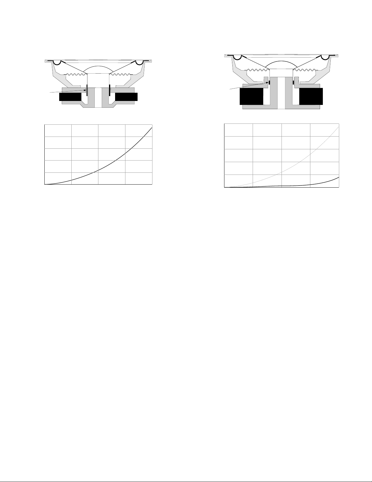
To eliminate this problem all three CS6 drivers use an unusual short coil/long gap system where the coil is much shorter than the
magnetic gap. Therefore, even when the coil moves a considerable distance from its rest position, it continues to be acted upon only by
the uniform magnetic field in the air gap and does not experience the changes in magnetic field strength with position as in the
6
Page 8
Conventional – long coil / short gap
THIEL CS6 – short coil / long gap
coil
10
8
6
4
2
Total Harmonic Distortion – %
0
2
468
peak excursion – ±mm
coil
10
8
6
4
2
Total Harmonic Distortion – %
0
2
468
peak excursion – ±mm
conventional system. As shown above, the distortion produced by the CS6 woofer’s short coil motor system at normal excursion levels is
only one-tenth that produced by the typical long coil system. Similar reductions are achieved in all the CS6’s drivers.
The third distortion mechanism is that the coil current is dependent not only on the driving voltage and the coil resistance but also on
the coil inductance. The problem is that the coil inductance varies with the amount of iron inside the coil and, therefore, with
conventional magnet system geometry, inductance changes during the excursions necessary to reproduce low frequencies. As the
diaphragm and coil move back, more of the coil is around the pole, increasing the inductance and decreasing the mid-frequency output
of the driver. As the coil moves forward, less of the coil is around the pole, the inductance decreases, and the mid-frequency response
increases. By this mechanism the frequency response of the speaker is modulated by driver excursion. This problem has been virtually
eliminated in all the CS6 drivers. The short coil design results in the entire coil surrounding the pole in all positions and therefore the
coil’s inductance does not change with the diaphragm position. In addition, the problem is further reduced by the copper sleeve which
reduces the inductance of the coil to a fraction of its normal value by acting as a shorted turn of a transformer secondary winding.
An additional problem is that the voice coil is an iron-core inductor. Iron-core inductors are not linear and therefore introduce
distortion. For this reason such inductors are avoided in high quality crossover systems. Nonetheless, one iron-core inductor remains in
the signal path— the driver’s voice coil. An additional benefit of the copper sleeve is that since it reduces the coil’s inductance it also
reduces the associated distortion.
7
 Loading...