

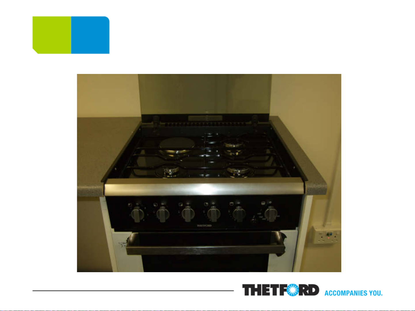
Swift ‘Aspire’ Cooker
Service Procedure Manual

Contents page
Slide 1: Front Page
Slide 2: Contents Page
Slides 3 & 4: The Fascia
Slides 5 – 7: The Hob Pressing
Slides 8 – 10: T he Thermocouple
Slides 11 & 12: The Ignition Electrode
Slide 13 – 15: T he Shut Off Mechanism
Slides 16 & 17: The 12v Spark Generator
Slide 18: Hotplate, Switch and 230v Generator Wiring Drawing
Slides 19 – 21: T he 12v Fans
Slides 22 – 25: The Grill Burner
Slides: 26 & 27: The Hob/Grill Gas Burner Valve
Slides 28 – 30: T he Thermostatic Valve
Slides 31 – 33: Dealer Time Allowances
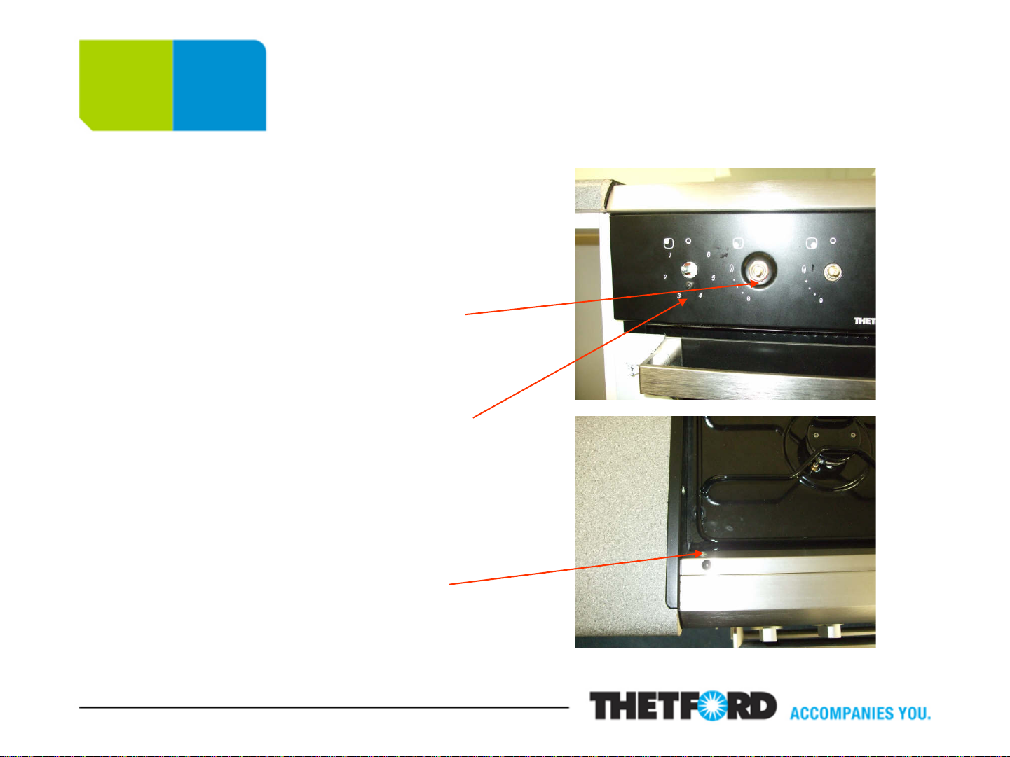
The Fascia
Remove control knobs
Remove 2 x 16mm locking nuts
and fibre washers
Remove 2 x screws below electric
hotplate switch and below oven
valve
Remove 2 x screws from profile
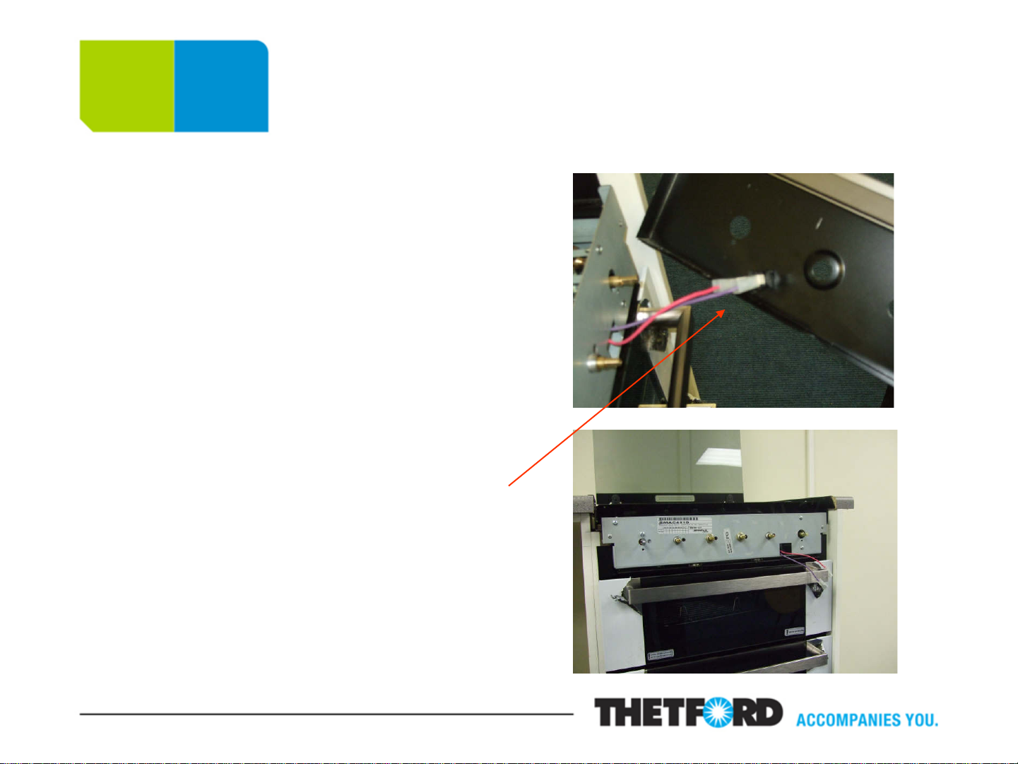
The Fascia, continued
Lift and pull profile forward in
order to remove fascia from
pressing
Remove 2 spade connectors
from ignition switch (these are
not polarity sensitive)
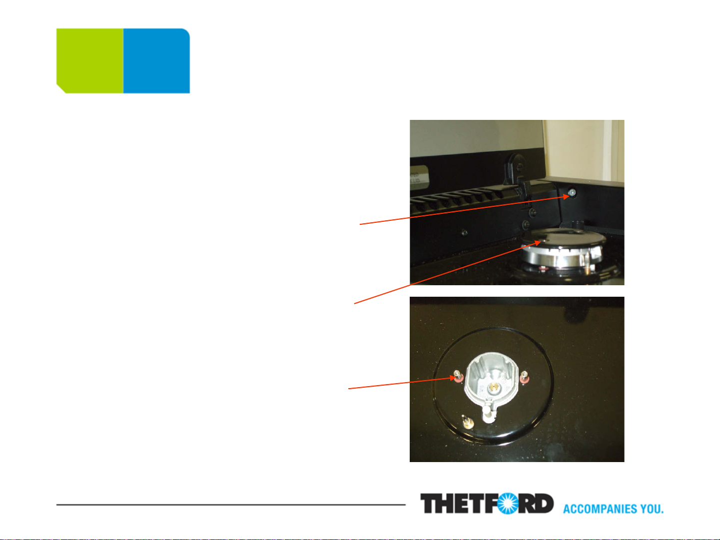
The Hob Pressing
Remove pan support
Remove 4 hob side trim screws
(PZ2 screwdriver)
Remove screws on burner caps
(PZ1 screwdriver)
Remove burner cup fixing studs
(5mm socket)

The Hob Pressing, continued
Loosen grub screws on hinges
and lift out glass lid
Loosen 4 dome headed screws
on hinges
Remove 2 screws on rear trim
that secure pressing
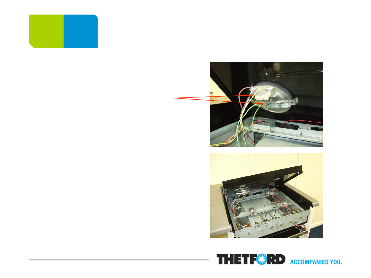
The Hob Pressing, continued
Lift pressing from the front and
remove cables and earth
connection from hotplate
(please note cable
configuration – see diagram)
Slide back of pressing from
under rear trim
Reverse process when
replacing hob panel with new.
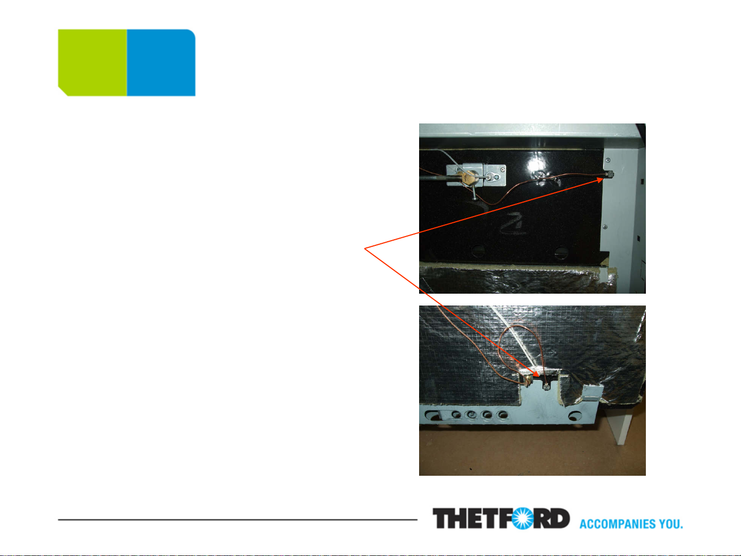
The Thermocouple
Disconnect and remove cooker
from its housing.
Lift up the hob pressing t o gain
access to the components below.
Both the oven and grill have earth
straps coming attached to the
thermocouples. Ensure that the
earth strap is fitted/not loose before
removing the fixing screw/locking
nut holding the thermocouple to the
respective burner. Remove the
spade fitting from the v al v e and
replace.
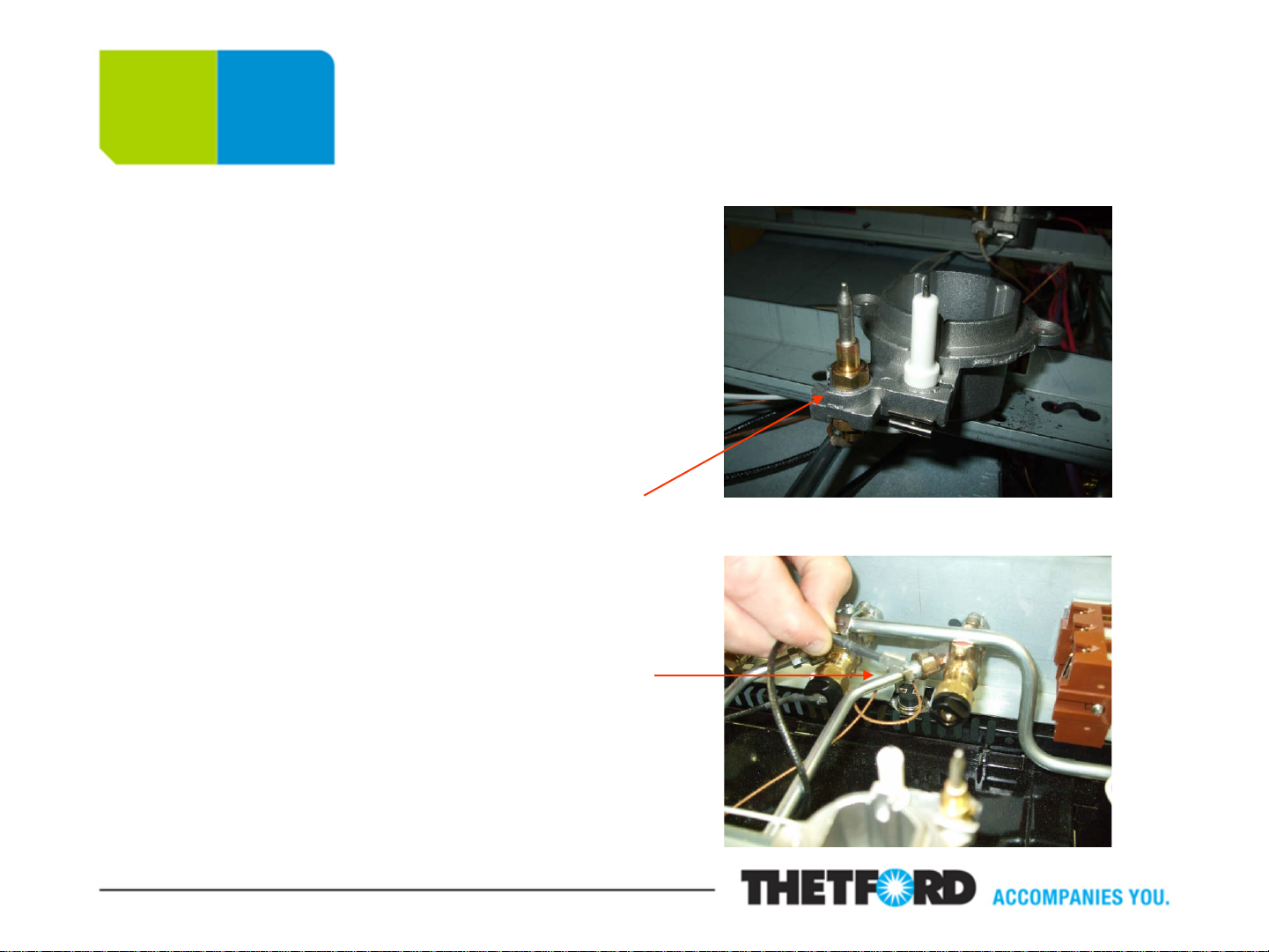
The Thermocouple, continued
There are two thermocouples
for the hob burners. One,
which is black, goes from the
valve to the shut off mechanism
and the second, which is
copper, goes from the burner to
the shut off mechanism.
Trace the relevant
thermocouple back to the shut
off mechanism and pull off the
spade fitting. If the
thermocouple is for the gas
valve pull off the spade fitt ing
and replace.
 Loading...