


TM
Terminator
DS/DE
In-Line Splice/End Termination Kit
INSTALLATION PROCEDURES
For In-Line Splice Connection and
End Termination Applications
TerminatorTM DS/DE
The following installation procedures are suggested guidelines
for the installation of termination connection systems. They are
not intended to preclude the use of other methods and good
engineering or field construction practices.
Receiving, Storing and Handling . . .
1. Inspect materials for damage incurred during shipping.
2. Report damages to the carrier for settlement.
3. Identify parts against the packing list to ensure the proper
type and quantity has been received.
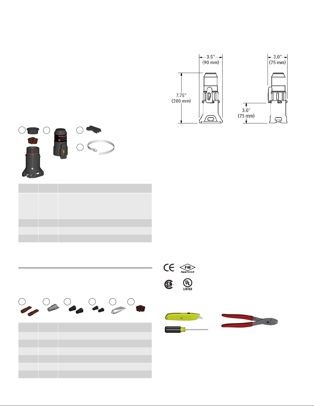
Kit Contents . . .
1
Item Quantity Description
1 1
2 1 Splice Cap
3 1 Banding Guide
4 1 Banding
2
3
4
Expediter Assembly
Threaded Grommet Compressor
Grommet
Support Base with O-Ring
Dimensions . . .
Installation Precautions . . .
• To minimize the potential for arcing and fire caused by product
damage or improper installation use ground-fault protection.
The National Electrical Code (NEC) and Canadian Electrical Code
(CEC) require ground-fault protection of equipment for each
branch circuit supplying electric heat tracing.
• Installation must comply with Thermon requirements and be in
stalled in accordance with the NEC, CEC, or any other applicable
national and local codes.
• Component approvals and performance ratings are based on
the use of Thermon specified parts only.
• De-energize all power sources before opening enclosure.
• Keep ends of heating cable and kit components dry before and
during installation.
-
Order Separately . . .
SCTK Splice Connection Termination Kits (per cable)
SCTK-1D for BSX, RSX, TSX, VSX
SCTK-2D for KSX, HTSX,
SCTK-3D for HPT, FP
1
Item Quantity Description
1 2 Splice Connection Boots
2 1 Large Wire Nut
3 2 Medium Wire Nuts
4 2 Small Wire Nuts
5 1 RTV Tube
6 1 GRW-G Grommet (SCTK-3D only)
2
43 5
Certifications/Approvals . . .
IP66 NEMA/Type 4X -60°C ≤ Ta ≤ +55°C
Ordinary & Hazardous Locations
Class I, Division 2, Groups A, B, C, & D, Zone 2 IIC
Class II, Division 2, Groups F & G, Class III
Listed Heat Tracing Cable System 137M
6
Tools Required . . .
1

TerminatorTM DS/DE
300 mm
(12")
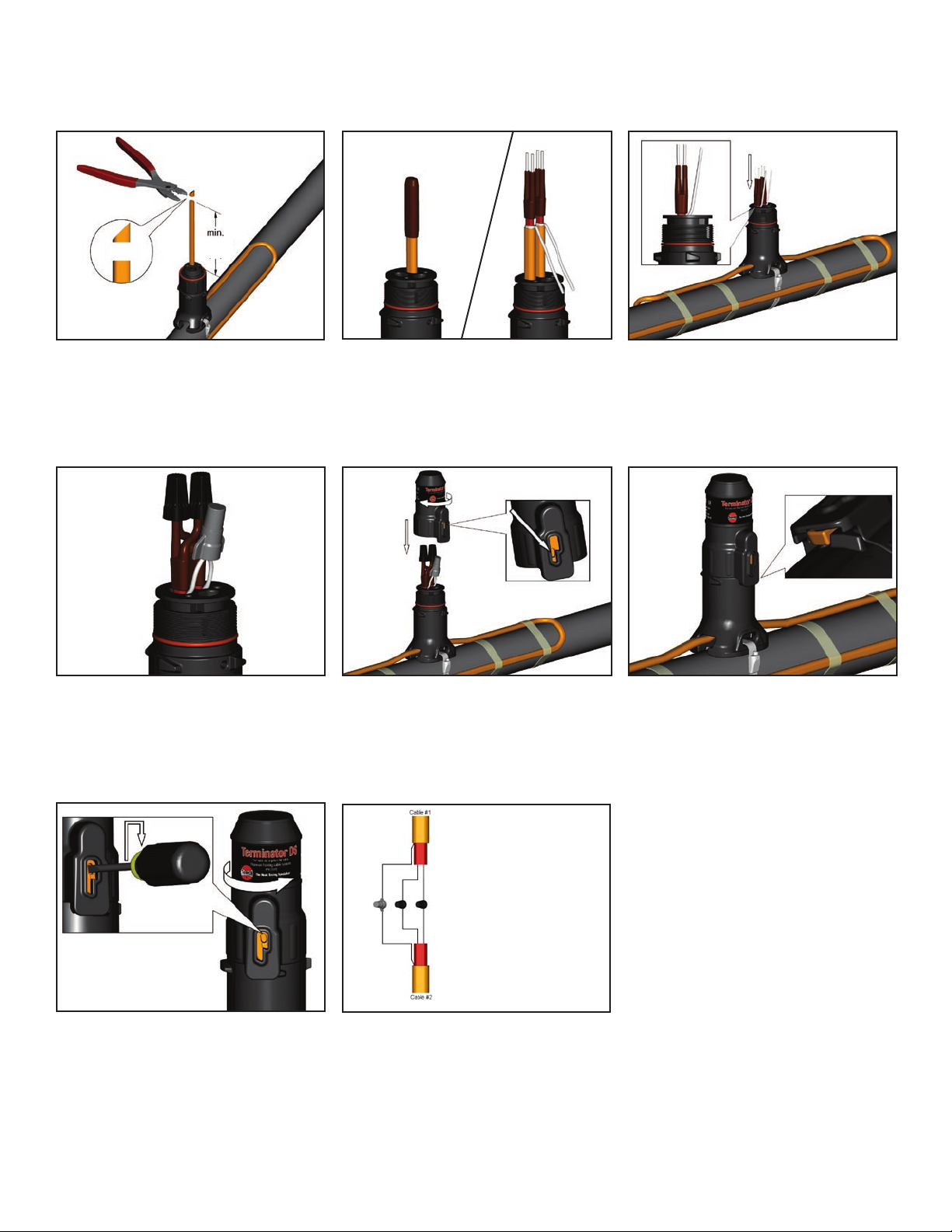
1a. For one or two cables. Locate bus connection
(HPT and FP only) and cable as shown. Cut end
of cable at angle to aid in piercing grommet. Leave
additional cable for expansion loop.
1b. Two cables.
300 mm
(12")
If mounted on bottom of pipe, punch out weep
hole.
3. Slide expediter toward pipe and route cable
through support base entry.
2b. Two cables.2a. For one or two cables. Insert cable into expediter.
4. Insert banding guide into expediter and snap into
place.
5. Mount expediter to pipe using pipe band. Do not
band over cable.
2
100 mm
(4")
INSTALLATION PROCEDURES
6. Cut off end of cable.
9. For splice connections: Connect bus wires using
small wire nuts (for BSX, HTSX, KSX and TSX) or
medium wire nuts (for RSX, VSX, HPT and FP).
Connect braid wires using large wire nut. See
wiring details for splice connections.
7. Terminate cable with appropriate PETK or SCTK
termination kit. Refer to kit installation instructions.
PETK Kit for Power/End Terminations
SCTK Kit for Splice Connections
8. Push excess cable back through expediter. Tape
cable expansion loop to pipe.
10. Tighten cap securely. 11. Completed splice/end kit. Make sure latch mecha-
nism is in the locked position.
Wiring Details for Splice Connections
12. To remove cap, lift latch mechanism and unscrew
cap.
In-Line Splice.
3

Form No. 50842 (03/06)
THERMON . . . The Heat Tracing Specialists
®
100 Thermon Dr. • PO Box 609 • San Marcos, TX 78667-0609
Phone: 512-396-5801 • Facsimile: 512-396-3627 • 1-800-820-HEAT
www.thermon.com In Canada call 1-800-563-8461
Specifications and information subject to change without notice.
 Loading...