


SafeTraceTM Steam Tracers
INSTALLATION PROCEDURES
SafeTraceTM Steam Tracers
The following installation procedures are suggested guidelines for the installation of SafeTrace BTS, SLS-IT and DLS-IT tracers. They are not intended to preclude the use of other methods and good engineering or field construction practices.
Receiving, Storing and Handling . . .
1.Inspect materials for damage incurred during shipping. Report damages to the carrier for settlement.
2.Identify the SafeTrace tubing to ensure the proper type and quantity has been received. Boxes and reels are marked on the outside with the SafeTrace part number, length, product description, weight and customer purchase order number. Compare information on box or reel with packing slip and purchase order to verify receipt of correct shipment.
•Lengths shorter than 50 m are shipped in heavyweight cardboard boxes.
•Lengths greater than 50 m are shipped on non-return
able |
wooden reels. |
3.The ends of SafeTrace tubing are factory-sealed to prevent dirt, moisture and insect intrusion. As a preventive measure, keep ends sealed until final connections are made. Cut ends may be temporarily sealed with plastic wrap and tape.
4.Cardboard boxes and wooden reels of product should be stored indoors away from standing water. However, wooden reels may be stored outdoors using a protective covering.
5.SafeTrace is shipped with the end of the tubing strapped to the side of the wooden reel. Use caution when releasing the end of the tracer from the reel as it is under tension and may recoil when released.
Surface Preparation . . .
1.Verify that the process piping has been pressure-tested to a pressure equal to or greater than that which will be used under normal operation prior to installing SafeTrace tubing. Repair any leaks before beginning installation of tracer tubing.
2.Surface areas where SafeTrace is to be installed must be reasonably clean. Remove dirt, rust and scale with a wire brush and oil and grease films with a suitable solvent.
Tracer Layout . . .
1.Determine circuit lengths and number of fittings prior to uncoiling the SafeTrace tubing since uncoiling and recoiling will “work harden” the tubing.
2.For long straight piping runs, a 300 mm diameter expansion loop must be provided at 18 to 30 m intervals.
3.If multiple passes are required, convection tracers may be doubled back where allowable pressure drops are not exceeded.
3.To uncoil and straighten the tubing, anchor the loose end of the tubing on a flat surface and roll the hand coil or shipping reel. If additional straightening is needed, apply tension to the tube.
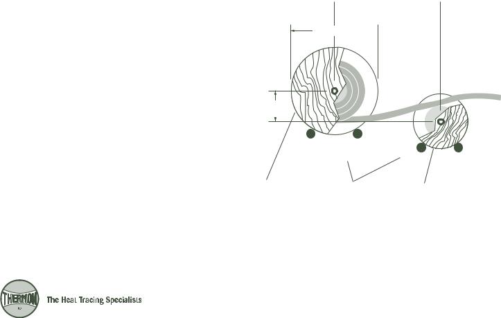
4.Wooden spools of SafeTrace containing long lengths of tubing can be placed on a pay-off tray as shown in Illustration A below. To “pay-off” the SafeTrace tubing, place the reel containing the tubing on one tray allowing the tracer tubing to freely spool from the bottom of the reel.
5.Straighten the tubing by utilizing a counterspool located in front of the reel containing the tracer tubing (see Illustration A). The counterspool should be located at a distance of 2½ times the diameter of the SafeTrace reel. Include a vertical offset of 200 to 250 mm between the reel centers.
Illustration A: Tracer Payout

 2.5 x Diameter A

Diameter A 

200-250 mm
|
|
|
|
|
|
|
|
SafeTrace Reel |
Pay-off Trays |
|
Counterspool |
1

INSTALLATION PROCEDURES
Installation on Straight Run Piping . . .
1.Install SafeTrace in accordance with Illustrations B and C below. Run the tubing parallel and in direct contact with the process piping where possible. If more than two tracers are used, they should be equally spaced circumferentially around the pipe.
2.For ease of installation and maintenance, the SafeTrace tubing should be located on the most accessible surface of the process piping. Tracer location does have an effect on heat transfer delivery; however, choosing a location convenient for installation and maintenance generally outweighs any heat transfer improvement provided by optimizing tracer location.
3.Attach SafeTrace to the process piping by utilizing 2½ wraps of Thermon’s FT-1H polyester fiber attachment tape. Tubing should be firmly secured to the piping on
300 mm centers to provide consistent heat transfer delivery. Refer to Tables 1 and 21 below to calculate the number of rolls of FT-1H attachment tape2 required based on the pipe diameter. Use Table 1 for BTS installations and Table 2 for DLS-IT and SLS-IT installations.
Notes . . .
1.Tables 1 and 2 assume circumferential bands every 300 mm along the length of the process piping.
2.FT-1H attachment tape is 12 mm wide by 33 m long with a maximum exposure temperature of 260°C.
Illustration B: Tracer Attachment
(See Installation Item 2 above)
SafeTrace |
FT-1H Attachment Tape |
|
Process Piping |
|
(Typical) |
|
|
|
300 mm |
300 mm |
300 mm |
Illustration C: Tracer Location
(See Installation Item 2 above)
Insulation
(Typical)
Process Pipe
(Typical)
FT-1H Attachment
Tape (Typical)
SafeTrace
(Typical)
45°
120°
120°

 120° 45°
|
|
Single Tracer |
|
|
Dual Tracer |
|
|
Triple Tracer |
|
|
|
|||
|
|
|
Table 1: FT-1H Attachment Tape Allowance for BTS |
|
|
|
|
|||||||
Pipe Size |
1½ |
2 |
3 |
4 |
6 |
8 |
10 |
12 |
14 |
16 |
18 |
20 |
24 |
30 |
in (mm) |
(40) |
(50) |
(80) |
(100) |
(150) |
(200) |
(250) |
(300) |
(350) |
(400) |
(450) |
(500) |
(600) |
(750) |
Length of Pipe/Roll |
33.5 |
29.0 |
21.3 |
16.8 |
10.7 |
9.1 |
7.6 |
6.1 |
5.8 |
4.9 |
4.6 |
4.0 |
3.4 |
2.7 |
m |
|
|
|
|
|
|
|
|
|
|
|
|
|
|
|
|
Table 2: FT-1H Attachment Tape Allowance for DLS-IT and SLS-IT |
|
|
|
|
||||||||
Pipe Size |
1½ |
2 |
3 |
4 |
6 |
8 |
10 |
12 |
14 |
16 |
18 |
20 |
24 |
30 |
in (mm) |
(40) |
(50) |
(80) |
(100) |
(150) |
(200) |
(250) |
(300) |
(350) |
(400) |
(450) |
(500) |
(600) |
(750) |
Length of Pipe/Roll |
29.0 |
24.4 |
18.3 |
15.2 |
10.7 |
9.1 |
7.0 |
6.1 |
5.5 |
4.9 |
4.5 |
4.0 |
3.4 |
2.7 |
m |
|
|
|
|
|
|
|
|
|
|
|
|
|
|
2
 Loading...