

Page 1

OS7 User’s Manual
N2350/N4350
Page 2

Copyright and Trademark Notice
Thecus and other names of Thecus products are registered trademarks of Thecus
Technology Corp. Microsoft, Windows, and the Windows logo are registered
trademarks of Microsoft Corporation. Apple, iTunes and Apple OS X are registered
trademarks of Apple Computers, Inc. All other trademarks and brand names are
the property of their respective owners. Specifications are subject to change
without notice.
Copyright © 2017 Thecus Technology Corporation. All rights reserved.
About This Manual
All information in this manual has been carefully verified to ensure its correctness.
In case of an error, please provide us with your feedback. Thecus Technology
Corporation reserves the right to modify the contents of this manual without
notice.
Product name: N2350/N4350
Manual Version: 1.5
Release Date: 2017/06
Limited Warranty
Thecus Technology Corporation guarantees all components of Thecus NAS
products are thoroughly tested before they leave the factory and should function
normally under general usage. In case of any system malfunctions, Thecus
Technology Corporation and its local representatives and dealers are responsible
for repair without cost to the customer if the product fails within the warranty
period and under normal usage. Thecus Technology Corporation is not responsible
for any damage or loss of data deemed to be caused by its products. It is highly
recommended that users conduct necessary back-up practices.
Check the functions that are available on your particular Thecus NAS model at:
http://www.Thecus.com
2
Page 3

Safety Warnings
For your safety, please read and follow the following safety warnings:
● Read this manual thoroughly before attempting to set up your Thecus IP
storage.
● Your Thecus IP storage is a complicated electronic device. DO NOT
attempt to repair it under any circumstances. In the case of malfunction,
turn off the power immediately and have it repaired at a qualified service
center. Contact your vendor for details.
● DO NOT allow anything to rest on the power cord and DO NOT place the
power cord in an area where it can be stepped on. Carefully place
connecting cables to avoid stepping or tripping on them.
● Your Thecus IP storage can operate normally under temperatures between
5°C and 40°C, with relative humidity of 20% – 85%. Using Thecus IP
storage under extreme environmental conditions could damage the unit.
● Ensure that the Thecus IP storage is provided with the correct supply
voltage. Plugging the Thecus IP storage to an incorrect power source could
damage the unit.
● Do NOT expose Thecus IP storage to dampness, dust, or corrosive liquids.
● Do NOT place Thecus IP storage on any uneven surfaces.
● DO NOT place Thecus IP storage in direct sunlight or expose it to other
heat sources.
● DO NOT use chemicals or aerosols to clean Thecus IP storage. Unplug the
power cord and all connected cables before cleaning.
● DO NOT place any objects on the Thecus IP storage or obstruct its
ventilation slots to avoid overheating the unit.
● Keep packaging out of the reach of children.
● If disposing of the device, please follow your local regulations for the safe
disposal of electronic products to protect the environment.
● Risk of explosion if battery is replaced by an incorrect type.
● Dispose of used batteries according to the instructions
3
Page 4

Table of Contents
Copyright and Trademark Notice .......................................... 2
About This Manual ................................................................ 2
Limited Warranty ................................................................. 2
Safety Warnings ................................................................... 3
Table of Contents ................................................................. 4
Chapter 1: Introduction ........................................................ 7
Overview .................................................................................... 7
Product Highlights ....................................................................... 7
Package Contents ........................................................................ 9
N2350 ...................................................................................... 10
Front Panel .................................................................................... 10
Rear Panel .................................................................................... 11
N4350 Series ........................................................................... 12
Front Panel .................................................................................... 12
Rear Panel .................................................................................... 13
Chapter 2: Hardware Installation ....................................... 14
Overview .................................................................................. 14
Before You Begin ....................................................................... 14
Cable Connections ..................................................................... 14
Chapter 3: First Time Setup ................................................ 16
Overview .................................................................................. 16
Thecus Setup Wizard ................................................................. 16
Typical Setup Procedure ............................................................. 18
Chapter 4: System Administration ...................................... 19
Overview .................................................................................. 19
Web Administration Interface ...................................................... 19
Menu Tree ..................................................................................... 20
Feedback for OS7.0 ........................................................................ 22
Quick System Log Info .................................................................... 22
Quick System Resource Monitor ....................................................... 22
System shut down and reboot ......................................................... 23
Language Selection ........................................................................ 23
Logout .......................................................................................... 23
Change Password ........................................................................... 23
Thecus OS7.0 Web Interface Revision ( FW v3.02.00 and after) ...... 24
Control Panel ............................................................................ 24
CONTROL ................................................................................. 24
Log and Notification ........................................................................ 24
Power & Hardware.......................................................................... 28
System Information ........................................................................ 32
Network ........................................................................................ 34
Regional Option ............................................................................. 40
External Device .............................................................................. 42
Monitor ......................................................................................... 42
Firmware Setting ........................................................................... 44
PRIVILEGE ................................................................................ 46
Share Folder .................................................................................. 46
Adding Folders ............................................................................... 47
Modify/Remove Folders ................................................................... 50
Local Account ................................................................................ 54
ADS ............................................................................................. 63
4
Page 5

LDAP ............................................................................................ 65
Storage .................................................................................... 66
Disk & RAID .................................................................................. 66
iSCSI ............................................................................................ 80
ISO Mount ..................................................................................... 92
Disk Clone & Wipe .......................................................................... 94
Services ................................................................................... 96
File Service ................................................................................... 96
Web Service ................................................................................ 104
SSH Service ................................................................................ 105
iTunes Service ............................................................................. 105
VPN Service ................................................................................. 107
UPnP Service ............................................................................... 110
Backup .................................................................................... 112
Local Backup ............................................................................... 112
Remote Backup ............................................................................ 122
Rsync Service .............................................................................. 130
USB Copy .................................................................................... 132
AWS S3 ...................................................................................... 135
System Failover ........................................................................... 135
Chapter 5: General User Login .......................................... 135
Overview ................................................................................. 135
General User Login Interface ...................................................... 135
Menu Tree ................................................................................... 136
Quick System Resource Monitor ..................................................... 136
Language Selection ...................................................................... 138
Logout ........................................................................................ 138
Change Password ......................................................................... 138
App Center .................................................................................. 138
File Center .................................................................................. 140
Photo Center ............................................................................... 142
Chapter 6: Tips and Tricks ................................................ 144
Access your NAS from Windows ................................................. 144
Share folder accessibility with associated login user account .......... 144
USB Storage Expansion ............................................................. 145
Remote Administration .............................................................. 145
Part I - Setup a DynDNS Account ................................................... 146
Part II - Enable DDNS on the Router............................................... 146
Part III - Setting up Virtual Servers (HTTPS) ................................... 146
Firewall Software Configuration .................................................. 146
Replacing Damaged Hard Drives ................................................. 147
Hard Drive Damage ...................................................................... 147
Replacing a Hard Drive ................................................................. 147
RAID Auto-Rebuild ....................................................................... 147
Chapter 7: Troubleshooting .............................................. 148
Forgot My Network IP Address ................................................... 148
Can't Map a Network Drive in Windows XP ................................... 148
Restoring Factory Defaults ......................................................... 148
Problems with Time and Date Settings ........................................ 149
Appendix A: Customer Support ......................................... 150
Appendix B: RAID Basics .................................................. 151
Overview ................................................................................. 151
Benefits .................................................................................. 151
Improved Performance ................................................................. 151
5
Page 6

Data Security .............................................................................. 151
RAID Levels ............................................................................. 151
Overview ................................................................................. 154
What is Active Directory?........................................................... 154
ADS Benefits ............................................................................ 154
Appendix D: Licensing Information .................................. 155
Overview ................................................................................. 155
Source Code Availability ............................................................ 155
CGIC License Terms .................................................................. 156
GNU General Public License ....................................................... 156
6
Page 7

Chapter 1: Introduction
Overview
Thank you for choosing the Thecus IP Storage Server. The Thecus IP storage is
an easy-to-use storage server that allows a dedicated approach to storing and
distributing data on a network. Data reliability is ensured with RAID features that
provide data security and recovery—over multiple Terabyte of storage are
available using RAID 5 and RAID 6. Gigabit Ethernet ports enhance network
efficiency, allowing Thecus IP storage to take over file management functions,
increase application and data sharing and provide faster data response. The
Thecus IP storage offers data mobility with a disk roaming feature that lets you
swap working hard drives for use in other Thecus IP storage, securing the
continuity of data in the event of hardware failure. The Thecus IP storage allows
data consolidation and sharing between Windows (SMB/CIFS), UNIX/Linux, and
Apple OS X environments. The Thecus IP storage’s user-friendly GUI supports
multiple Languages.
Product Highlights
File Server
First and foremost, the Thecus IP storage allows you to store and share files over
an IP network. With a Network Attached Storage (NAS) device, you can centralize
your files and share them easily over your network. With the easy-to-use webbased interface, users on your network can access these files in a snap.
FTP Server
With the built-in FTP Server, friends, clients, and customers can upload and
download files to your Thecus IP storage over the Internet with their favorite FTP
programs. You can create user accounts so that only authorized users have
access.
iTunes Server
With the built-in iTunes server capability, the Thecus IP storage enables digital
music to be shared and played anywhere on the network!
Printer Server
With the Thecus IP storage’s Printer Server, you can easily share an IPP printer
with other PCs connected to your network.
Multiple RAID
Thecus IP storage supports multiple RAID volumes on one system. So, you can
create RAID 0 for your non-critical data, and create RAID 1,5,6,50 or 60 (depend
on model) for mission-critical data. Create the RAID levels depending on your
needs.
iSCSI Capability
Thecus IP storage is not only a file server, but it also supports iSCSI initiators.
Your server can access Thecus IP storage as a direct-attached-storage over the
LAN or Internet. There is no easier way to expand the capacity of your current
application servers. All the storage needs can be centrally managed and deployed.
This brings ultimate flexibility to users.
Superior Power Management
7
Page 8

Thecus IP storage supports schedule power on/off. With this feature,
administrator can set at what time to turn on or off the system. This feature is a
big plus for people who want to conserve energy. Wake-On-LAN enables
administrator to remotely turn on the system without even leaving their own seat.
8
Page 9

Package Contents
N2350 Series/N4350 Series
The Thecus IP storage should contain the following common items:
● System Unit x1
● QIG (Quick Installation Guide) x1
● CD-Title (OS7 Universal CD)
● Ethernet Cable x1
● Accessory box x1
● HDD Compatibility list Card x1
● Multiple Languages Warranty Card x1
● Power adaptor cable tie x1
● Power adaptor x1
● Power cord x1
Please check to see if your package is complete. If you find that some items are
missing, contact your dealer.
9
Page 10
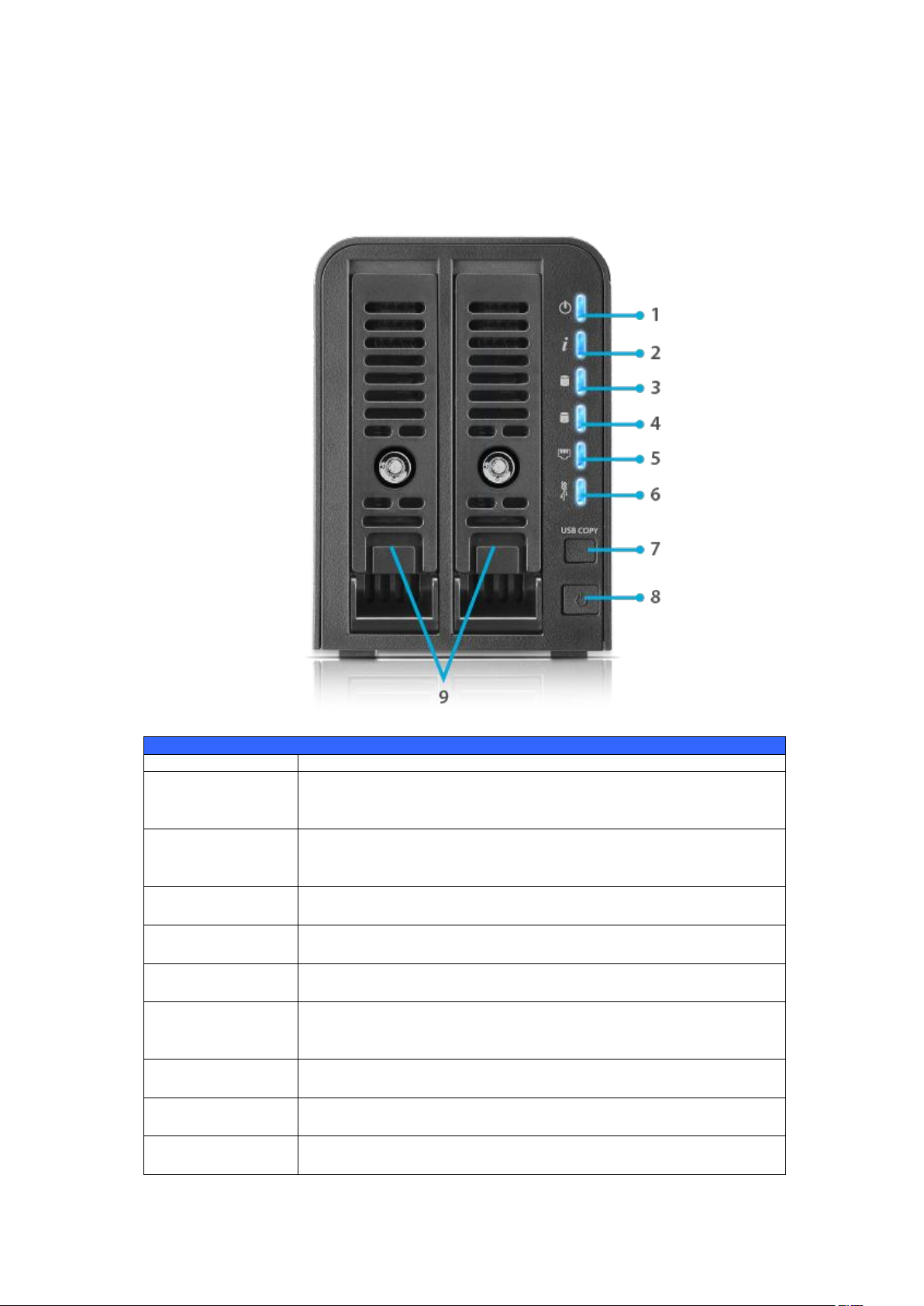
N2350
Front Panel
Item
Description
1. Power LED
Solid blue: System ready
Blinking blue: Power on process
Solid Orange: System with error occurred
2. System
status LED
Blinking blue: Diagnostic mode kick-in
Solid blue: Diagnostic completed
Solid Orange: System with error occurred
3. HDD1 LED
Blinking blue: HDD activity
Orange: HDD failure
4. HDD2 LED
Blinking blue: HDD activity
Orange: HDD failure
5. LAN LED
Solid blue: LAN Cable link
Blinking : Network activity
6. USB LED
Solid blue: Installed
Blinking blue: USB copy activity
Solid Orange: USB copy failure
7. USB Copy
Button
Copies USB storage contents to N2350.
8. Power
Button
Power the N2350 on/off.
9. HDD Trays
Two HDD Trays for two 2.5"/3.5" SATA HDDs with Hotswappable supports.
Front Panel
The Thecus N2350 front panel has the device’s controls, indicators, and hard disk
trays:
10
Page 11
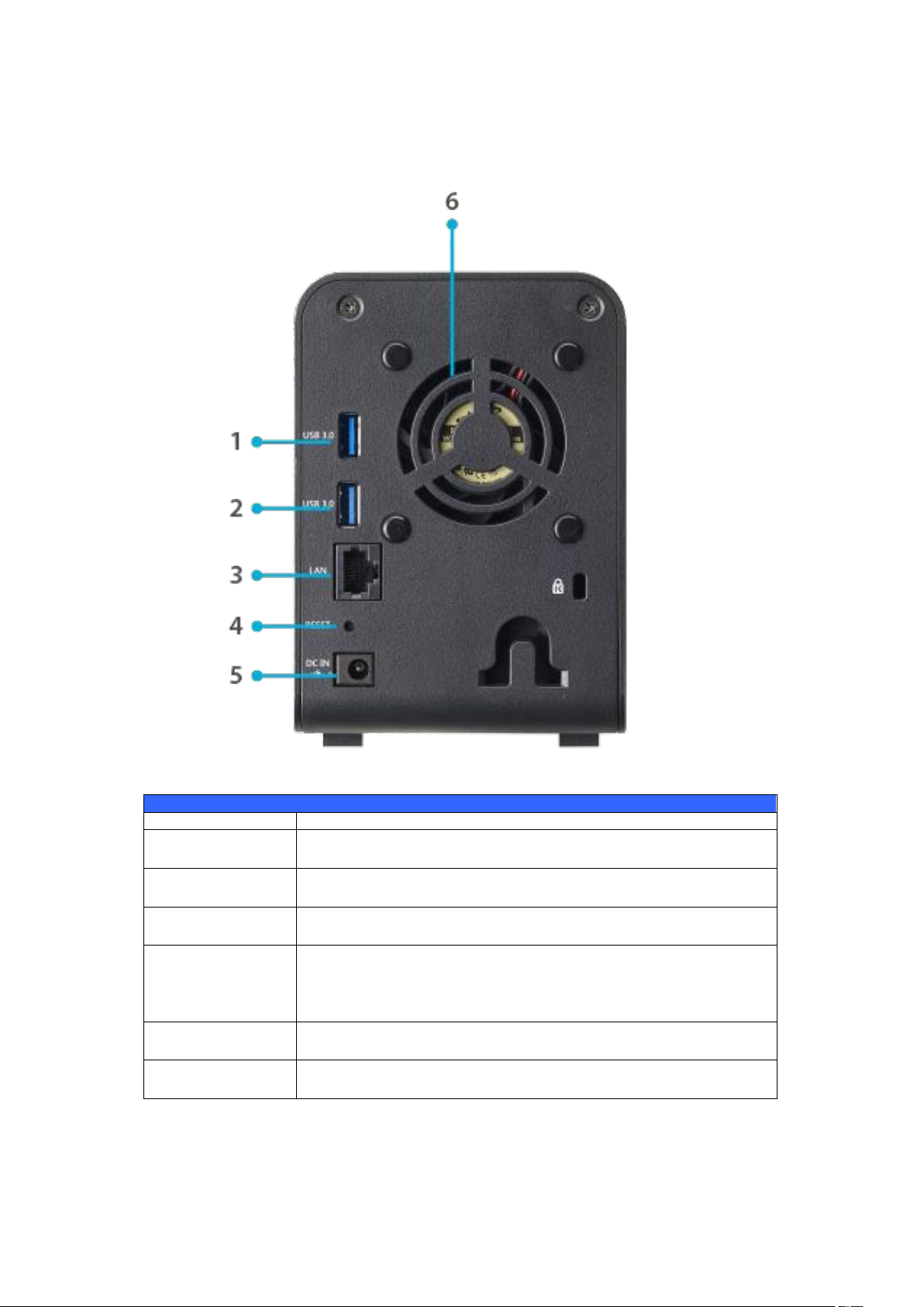
Rear Panel
Back Panel
Item
Description
1. USB 3.0 Port
USB 3.0 port for compatible USB devices, such as digital
cameras, USB disks, and USB printers.
2. USB 3.0 Port
USB 3.0 port for compatible USB devices, such as digital
cameras, USB disks, and USB printers.
2. LAN Port
LAN port for connecting to an Ethernet network through a
switch or a router.
4. Reset Button
Resets the N2350.
Pressing and holding the Reset button on the back for 1
seconds will reset your network setting and password, and
turn off Jumbo Frame Support.
5. Power
Connector
Connect the included power cords to this connector.
6. System Fan
System fan that exhausts heat from the unit.
The N2350 rear panel features ports and connectors.
11
Page 12
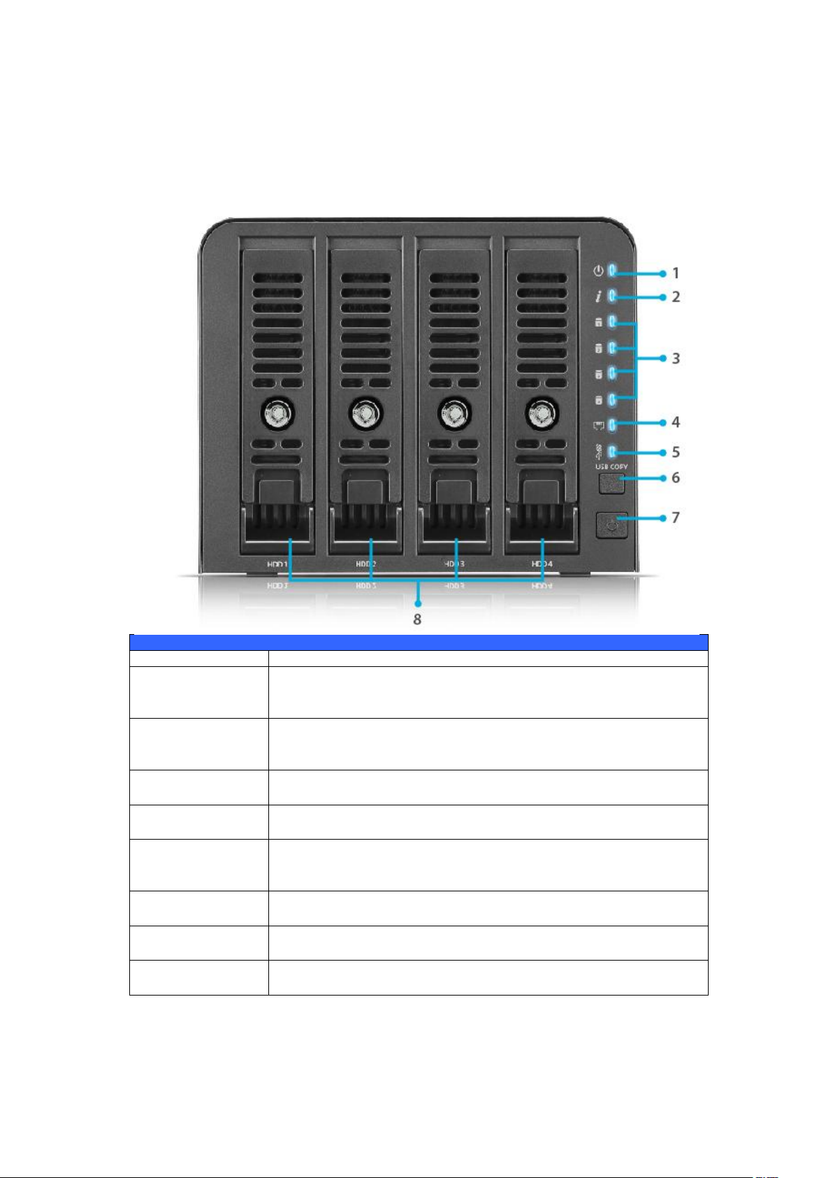
N4350 Series
Front Panel
Item
Description
1. Power LED
Solid blue: System ready
Blinking blue: Power on process
Solid Orange: System with error occurred
2. System
status LED
Blinking blue: Diagnostic mode kick-in
Solid blue: Diagnostic completed
Solid Orange: System with error occurred
3. HDD1-4 LED
Blinking blue: HDD activity
Orange: HDD failure
4. LAN LED
Solid blue: LAN Cable link
Blinking : Network activity
5. USB LED
Solid blue: Installed
Blinking blue: USB copy activity
Solid Orange: USB copy failure
6. USB Copy
Button
Copies USB storage contents to N4350.
7. Power
Button
Power the N4350 on/off.
8. HDD Trays
Two HDD Trays for two 2.5"/3.5" SATA HDDs with Hotswappable supports.
Front Panel
The Thecus N4350 Series front panel has the device’s controls, indicators, and
hard disk trays:
12
Page 13
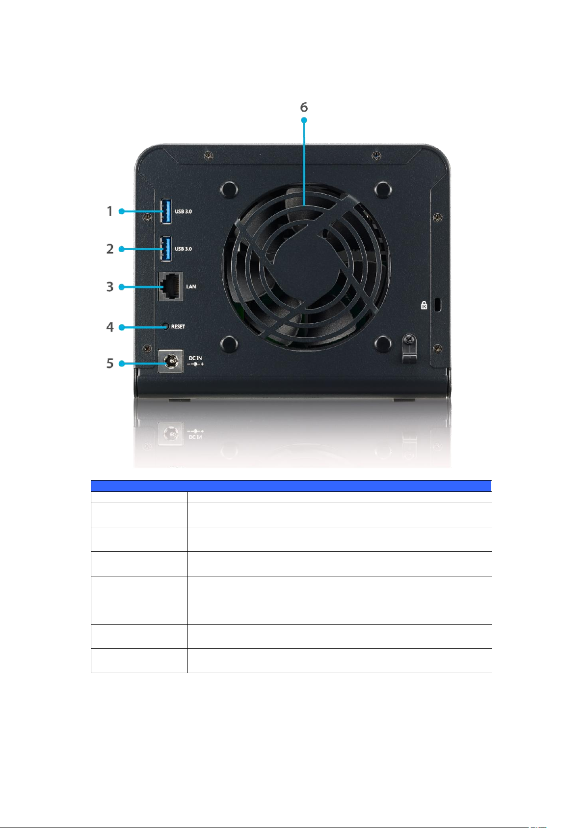
Rear Panel
Back Panel
Item
Description
1. USB 3.0 Port
USB 3.0 port for compatible USB devices, such as digital
cameras, USB disks, and USB printers.
2. USB 3.0 Port
USB 3.0 port for compatible USB devices, such as digital
cameras, USB disks, and USB printers.
3. LAN Port
LAN port for connecting to an Ethernet network through a
switch or a router.
4. Reset Button
Resets the N4350.
Pressing and holding the Reset button on the back for 1
seconds will reset your network setting and password, and
turn off Jumbo Frame Support.
5. Power
Connector
Connect the included power cords to this connector.
6. System Fan
System fan that exhausts heat from the unit.
The N4350 Series rear panel features ports and connectors.
13
Page 14
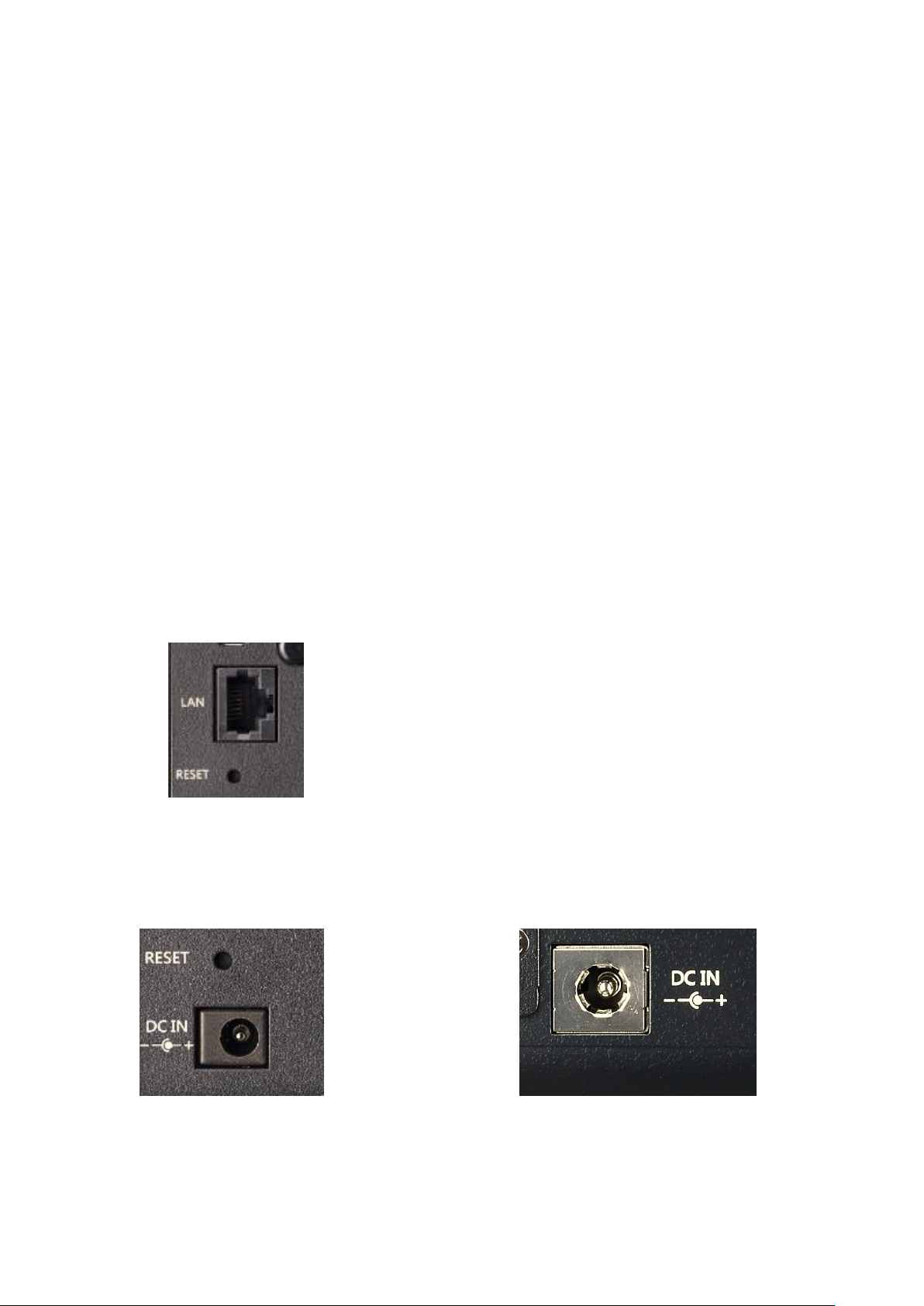
Chapter 2: Hardware Installation
▲ N2350/N4350
WAN/LAN1 port
▲N2350 Series power socket ▲N4350 Series power socket
Overview
Your Thecus IP storage is designed for easy installation. To help you get started,
the following chapter will help you quickly get your Thecus IP storage up and
running. Please read it carefully to prevent damaging your unit during installation.
Before You Begin
Before you begin, be sure to take the following precautions:
1. Read and understand the Safety Warnings outlined in the beginning of
the manual.
2. If possible, wear an anti-static wrist strap during installation to prevent
static discharge from damaging the sensitive electronic components on the
Thecus IP storage.
3. Be careful not to use magnetized screwdrivers around the Thecus IP
storage’s electronic components.
Cable Connections
To connect the Thecus IP storage product to your network, follow the steps below:
1. Connect an Ethernet cable from your network to the WAN/LAN1 port on
the back panel of the Thecus IP storage.
2. Connect the provided power adaptor and power cord into the power socket
on the back panel. Plug the other end of the cord into a surge protector
socket.
14
Page 15
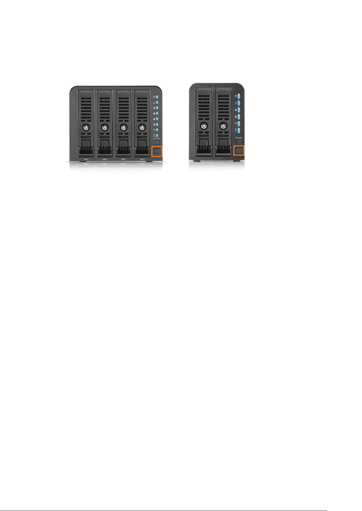
▲N4350 Series power button
▲N2350 Series power button
3. Press the power button on the Front Panel to boot up the Thecus IP
storage.
15
Page 16
Chapter 3: First Time Setup
NOTE
For MAC OS X users, double click on Thecus Setup Wizard .dmg file.
Overview
Once the hardware is installed, physically connected to your network, and
powered on, you can configure the Thecus IP storage so that it is accessible to
your network users. There are two ways to set up your Thecus IP storage: using
the Thecus Setup Wizard or the LCD display (Depend on models). Follow
the steps below for initial software setup.
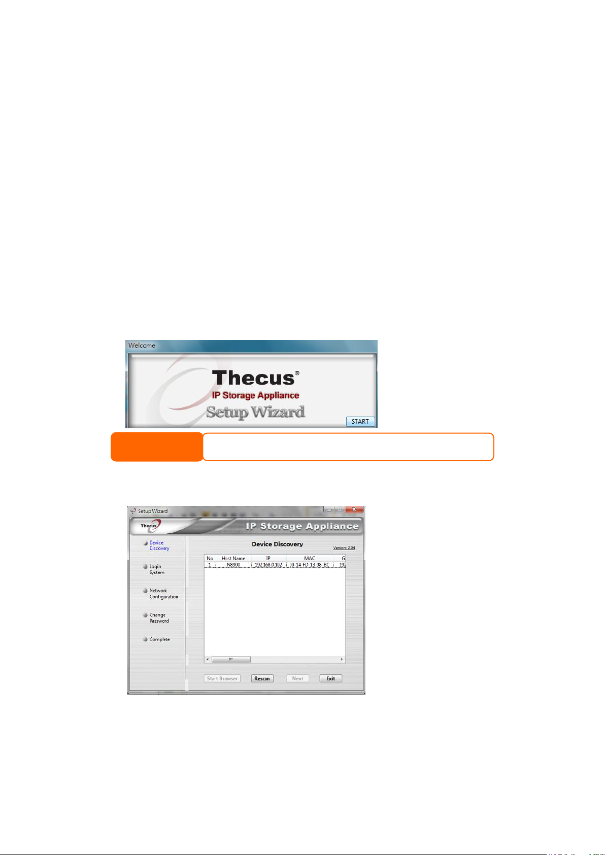
Thecus Setup Wizard
The handy Thecus Setup Wizard makes configuring Thecus IP storage a snap. To
configure the Thecus IP storage using the Setup Wizard, perform the following
steps:
1. Insert the installation CD into your CD-ROM drive (the host PC must be
connected to the network).
2. The Setup Wizard should launch automatically. If not, please browse your
CD-ROM drive and double click on Setup.exe.
3. The Setup Wizard will start and automatically detect all Thecus storage
devices on your network. If none are found, please check your connection
and refer to Chapter 7: Troubleshooting for assistance.
4. Select the Thecus IP storage that you like to configure.
5. Login with the administrator account and password. The default account
and password are both “admin”.
16
Page 17
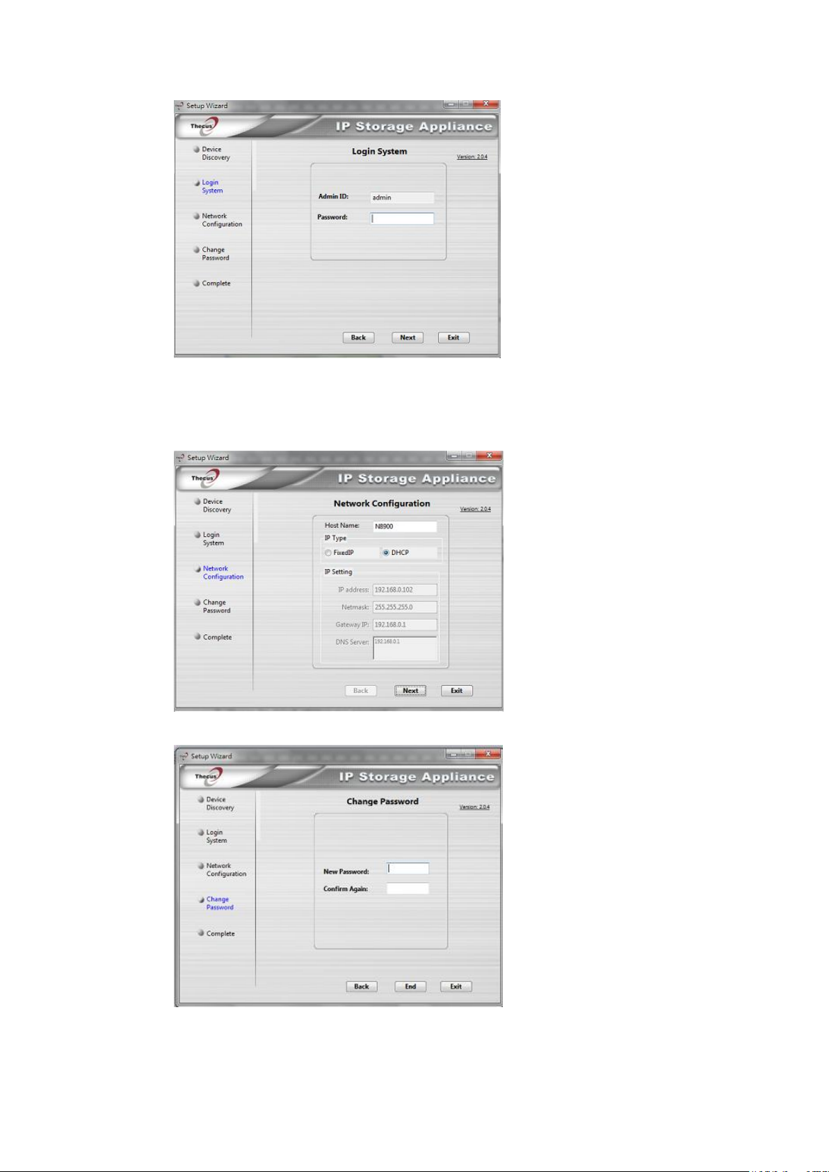
6. Name your Thecus IP storage and configure the network IP address. If
your switch or router is configured as a DHCP Server, configuring the
Thecus IP storage to automatically obtain an IP address is recommended.
You may also use a static IP address and enter the DNS Server address
manually.
7. Change the default administrator password.
8. Finished! Access the Thecus IP storage Web Administrator Interface by
pressing the Start Browser button. You can also configure another
17
Page 18
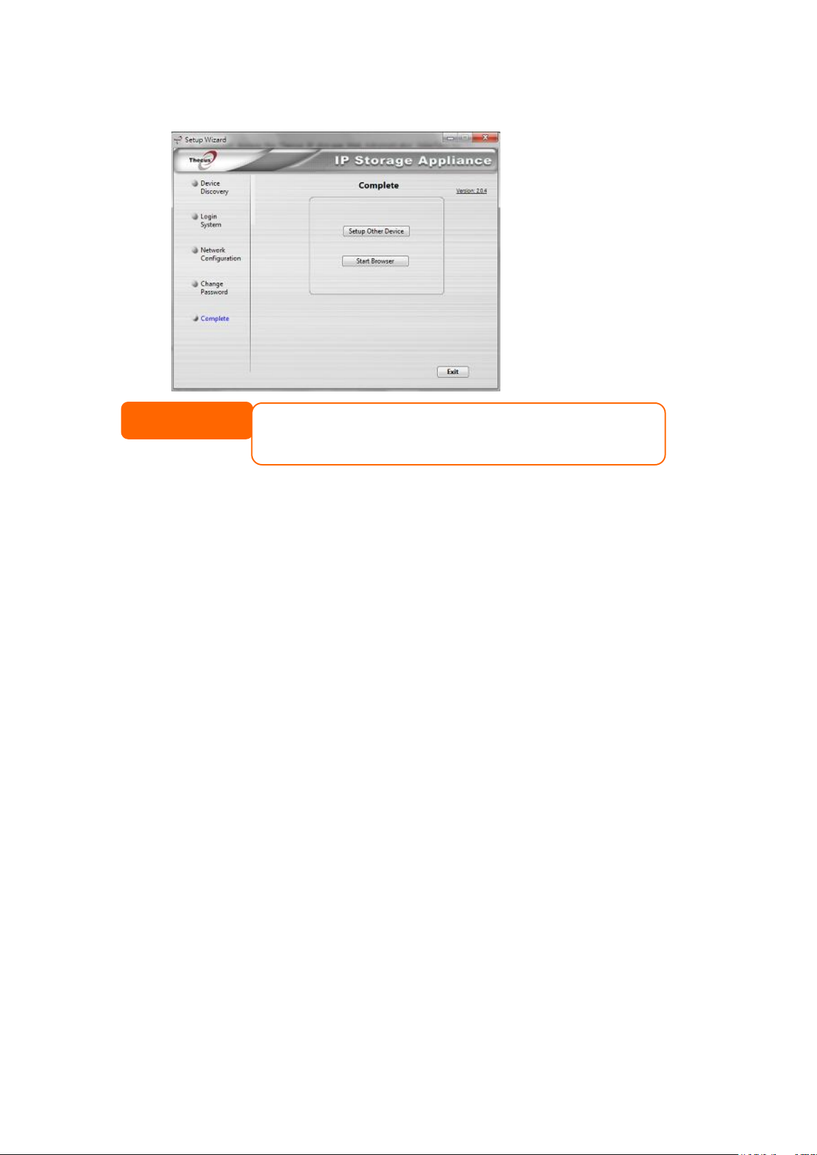
Thecus IP storage at this point by clicking the Setup Other Device button.
NOTE
The Thecus Setup Wizard is designed for installation on systems running
Windows XP/2000/vista/7/8/10 or Mac OSX or later. Users with other operating
systems will need to install the Thecus Setup Wizard on a host machine with
one of these operating systems before using the unit.
Press Exit to exit the wizard.
Typical Setup Procedure
From the Web Administration Interface, you can begin to setup your Thecus IP
storage for use on your network. Setting up the Thecus IP storage typically
follows the five steps outlined below.
Step 1: Network Setup
From the Web Administration Interface, you can configure the network settings of
the Thecus IP storage for your network. You can access the Network menu from
the control panel.
Step 2: RAID Creation
Next, administrators can configure their preferred RAID setting and build their
RAID volume. You can access RAID settings from the control panel of the Web
Administration Interface by navigating to Storage Management > Disk and
RAID.
Step 3: Create Local Users or Setup Authentication
Once the RAID is ready, you can begin to create local users for Thecus IP storage,
or choose to setup authentication protocols such as Active Directory (AD).
Step 4: Create Folders and Set Up ACLs
Once users are introduced into your network, you can begin to create various
folders on the Thecus IP storage and control user access to each using Folder
Access Control Lists.
Step 5: Start Services
Finally, you can start to setup the different services of Thecus IP storage for the
users on your network.
18
Page 19
Chapter 4: System Administration
NOTE
Your computer’s network IP address must be on the same subnet as the
Thecus IP storage. If the Thecus IP storage has default IP address of
192.168.1.100, your managing PC IP address must be 192.168.1.x, where x
is a number between 1 and 254, but not 100.
Overview
The Thecus IP storage provides an easily accessible Web Administration
Interface. With it, you can configure and monitor the Thecus IP storage
anywhere on the network.
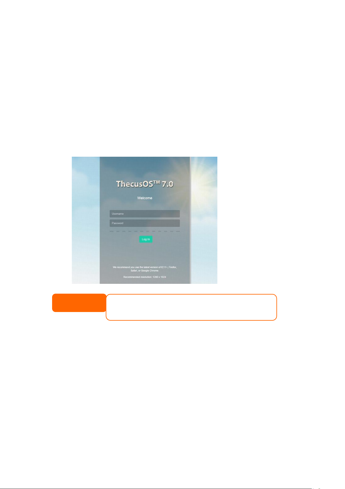
Web Administration Interface
Make sure your network is connected to the Internet. To access Thecus IP storage
Web Administration Interface:
1. Type the Thecus IP storage IP address into your browser. (Default IP
address is http://192.168.1.100)
2. Login to the system using the administrator user name and password. The
factory defaults are:
User Name: admin
Password: admin
※ If you changed your password in the setup wizard, use the new password.
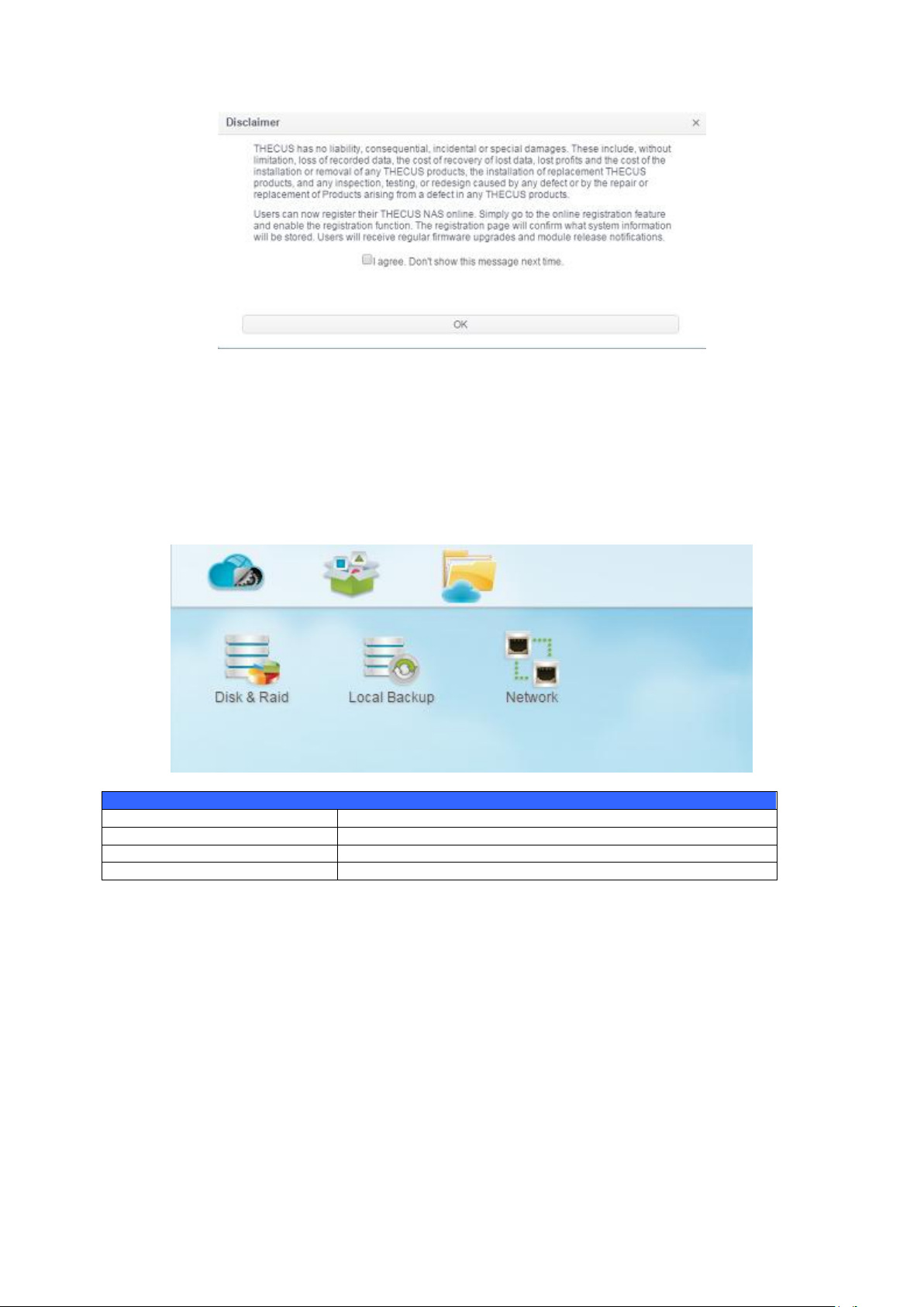
Once you are logged in as an administrator, the disclaimer page will appear as
below. Please click the check box if you do not want to have this page displayed
during the next login.
19
Page 20
Menu Bar
Item
Description
Control Panel
The Entry of system and function setting
App Center
The entry of App Center
File Center
The entry of File Center
Following the disclaimer page, you will see the Web Administration Interface.
From here, you can configure and monitor virtually every aspect of the Thecus IP
storage from anywhere on the network.
Menu Tree
The Menu Tree is where you will find all of the information screens and system
settings of Thecus IP storage. The various settings are placed in the following
groups on the menu bar.
Moving your cursor over any of these items and click, it will display the associated
screen for each topic.
Add/Remove Shortcut
The user interface allows the user to designate often used items and have them
display on the main screen area by add Shortcut. The figure below displays
system favorite functions.
20
Page 21
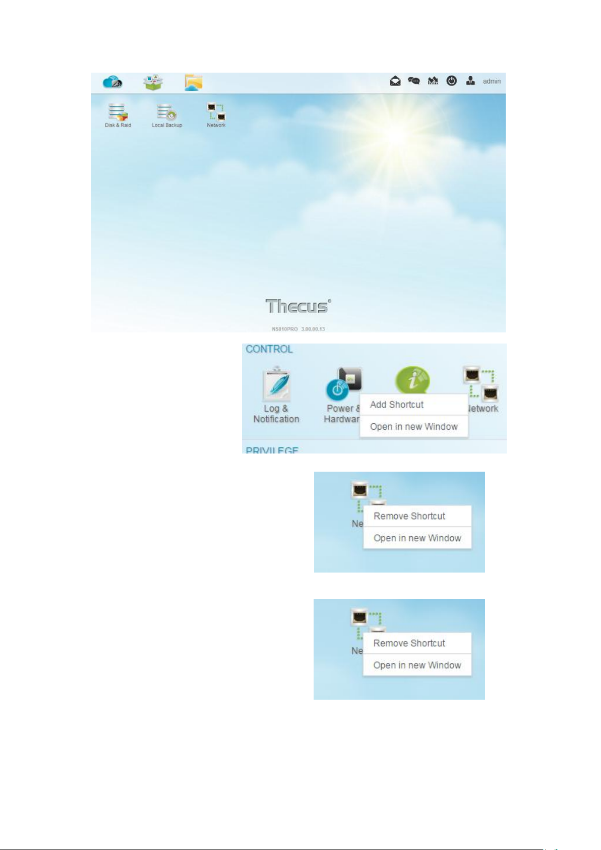
Administrators can add or
remove Shortcut by right
clicking the mouse and
selecting “Add Shortcut”
icon in each function screen.
See the figure below with
the red circled icon.
To remove “Shortcut” from main screen,
right click the mouse button and select
“Remove Shortcut”.
Open in New Window
To open associated function on the front
of screen, right click mouse and select
“Open in new window”.
21
Page 22
In the following sections, you will find detailed explanations of each function, and
how to configure your Thecus IP storage.
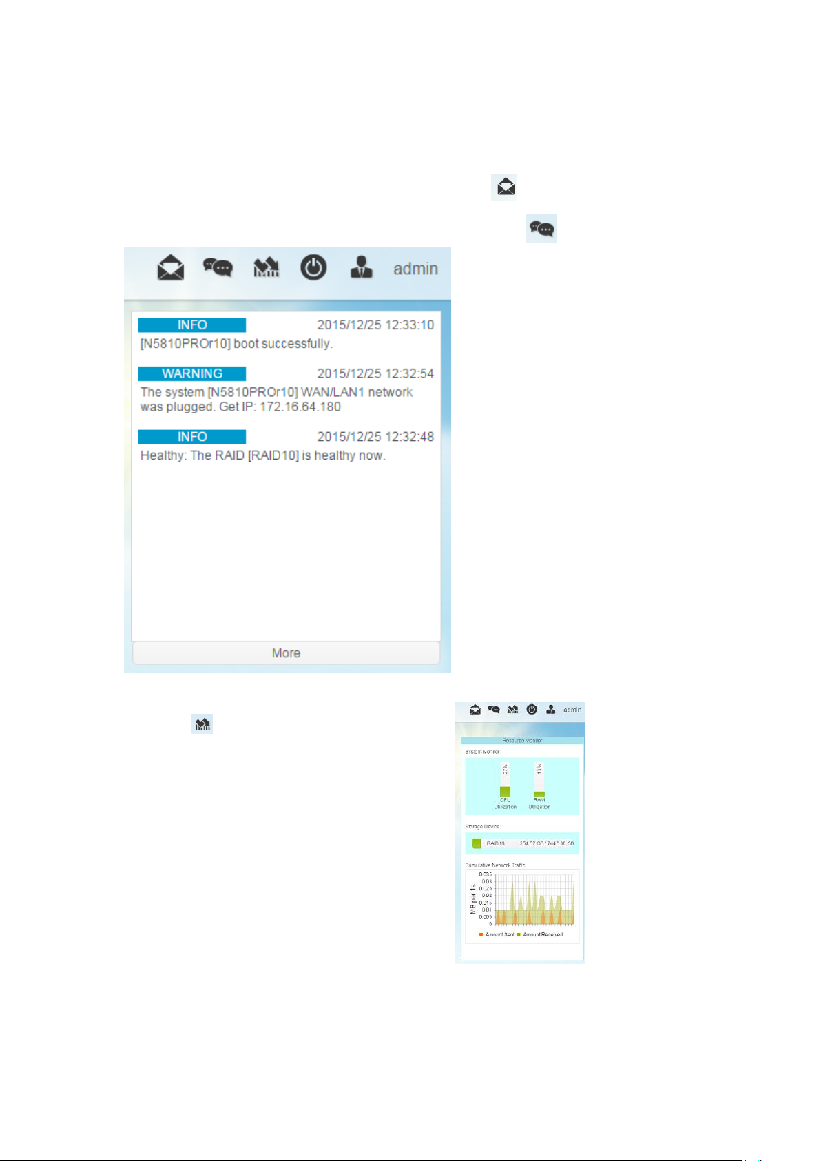
Feedback for OS7.0
On the top right hand corner of menu bar, click on and it will open the mail
sending screen, please provide your feedback.
Quick System Log Info
On the top right hand corner of the menu bar, click on and it will display
the system log info.
Quick System Resource Monitor
On the top right hand corner of the menu bar,
click on and it will display the
system resource monitor info
such as CPU, memory and storage usage. .
22
Page 23

System shut down and reboot
On the top right hand corner of the menu bar, click on , this is a shortcut to
shut down or reboot the system.
Language Selection
The Thecus IP storage supports multiple Languages,
including:
● English
● Japanese
● Traditional Chinese
● Simplified Chinese
● French
● German
● Italian
● Korean
● Spanish
● Russian
● Polish
● Portuguese
On the top right hand corner of menu bar, select desired
language from drop down list. This user interface will
switch to the selected language for Thecus IP storage.
Logout
Click on logout to quit Web Administration Interface.
Change Password
On the top right hand corner of menu bar, select Password item and the
Change Password screen will appear. Enter a new password in the New
Password box and confirm your new password in the Verify box. Click on
Change to confirm password changes.
23
Page 24
Thecus OS7.0 Web Interface Revision ( FW v3.02.00 and after)
Logs
Item
Description
The user guide please refers to URL below.
http://www.thecus.com/download/manual/OS7/Thecus%20Web%20Interface%2
0Revision_FW%20v3.02.00_after%20v2.pdf
Control Panel
The control panel has 5 main categories: CONTROL, PRIVILLEGE, STORAGE,
SERVICES and BACKUP. Please see below for explanation.
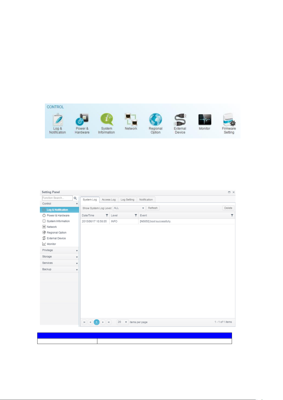
CONTROL
Log and Notification
System Log
From the Log & Notification menu, choose the System Log option and the
System Log screen will appear. This screen will show a history of system usage
and important events such as disk status, network information, and system
booting.
24
Page 25
Log Level
ALL: Provides all log information including system, warning,
and error messages.
WARN: Shows only warning messages.
ERROR: Shows only error messages.
Delete
Clear all log files.
Items per page □
Specify the desired number of lines to display per page.
Filters
Input desired value to filter unwanted items
|<< < > >>|
Use the forward ( > >>| ) and backward ( |<< < )
buttons to browse through the log pages.
Refresh
Reload logs
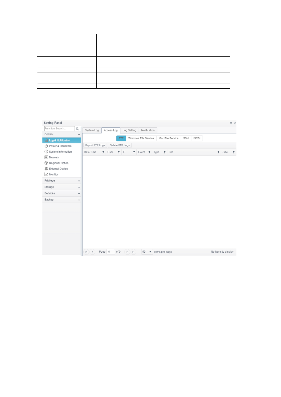
Access Log
The Access Log Support section allows administrators to choose associated
protocol and view user activity information.
Log Setting
To have user access details for associated system, Access Log Support must
be enabled and confirmed with “Apply” button, at the time all supported services
will restart. To view Access Log details, please go to Access Log section.
25
Page 26
User Access Log
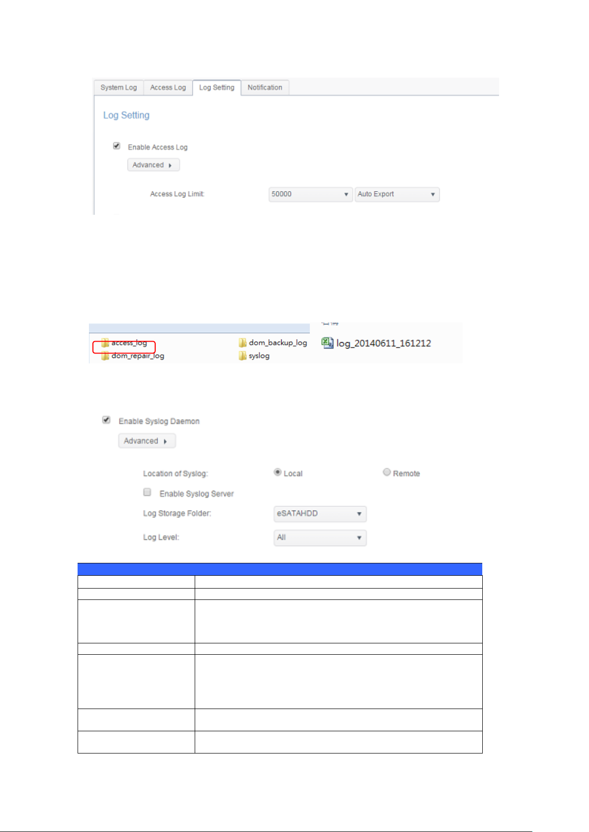
Log Setting
Item
Description
Enable Access Log
Enable or disable the Access Log service.
Access log limit
This can be selected from a dropdown list to export the
log(s) as a single file. Please also choose “Auto Export” or
“Auto Delete” once the log item exceeded the defined
number.
Enable Syslog Daemon
Enable or disable Syslog service.
Location of Syslog
Choose Local, all system logs will be stored in an associated
syslog folder filled in from next filed. And the syslog folder
will have file “messages” to store all system logs. If
Remotely has been selected, a syslog server is needed and
an IP address is required to fill in from next filed.
Enable Syslog Server
Checked to enable associated system can play a role as
syslog server while syslog location has select “Local”
Log Server IP
(Remote)
Input the remote syslog server IP address once syslog store
in remote server has selected
To export details from the User Access Log as a single file from target folder,
administrators must first select the desired number of records from the dropdown
list and also select the “Auto export” option. Please choose the number of logs to
export and click Apply to activate these settings.
Once (for example) 10,000 records have been reached, the log file will appear in
/NAS_public/access_log/
Syslog service can generate system logs to be stored locally or remotely.
Information can be obtained in two ways: locally and remotely.
26
Page 27
Log storage folder
(Local)
Select from a drop down share list, all of the system logs will
be stored on it. This syslog folder is applied to “syslog
server” or “syslog client” with “local” selected.
Log Level
The user can choose from 3 different levels. “All”,
“Warning/Error” or “Error”.
Apply
Click Apply to save changes.
Description
The user access list will record different activities for
supported protocols.
1. AFP: User login and logout.
2. FTP: User file deletion, uploads/downloads, folder
creation, object renaming, and login and logout.
3. iSCSI: User login and logout.
4. Samba: User file deletion, folder creation, folder opening,
and object reading, renaming, and writing.
5. SSH: User login and logout.
6. VPN: User login and logout
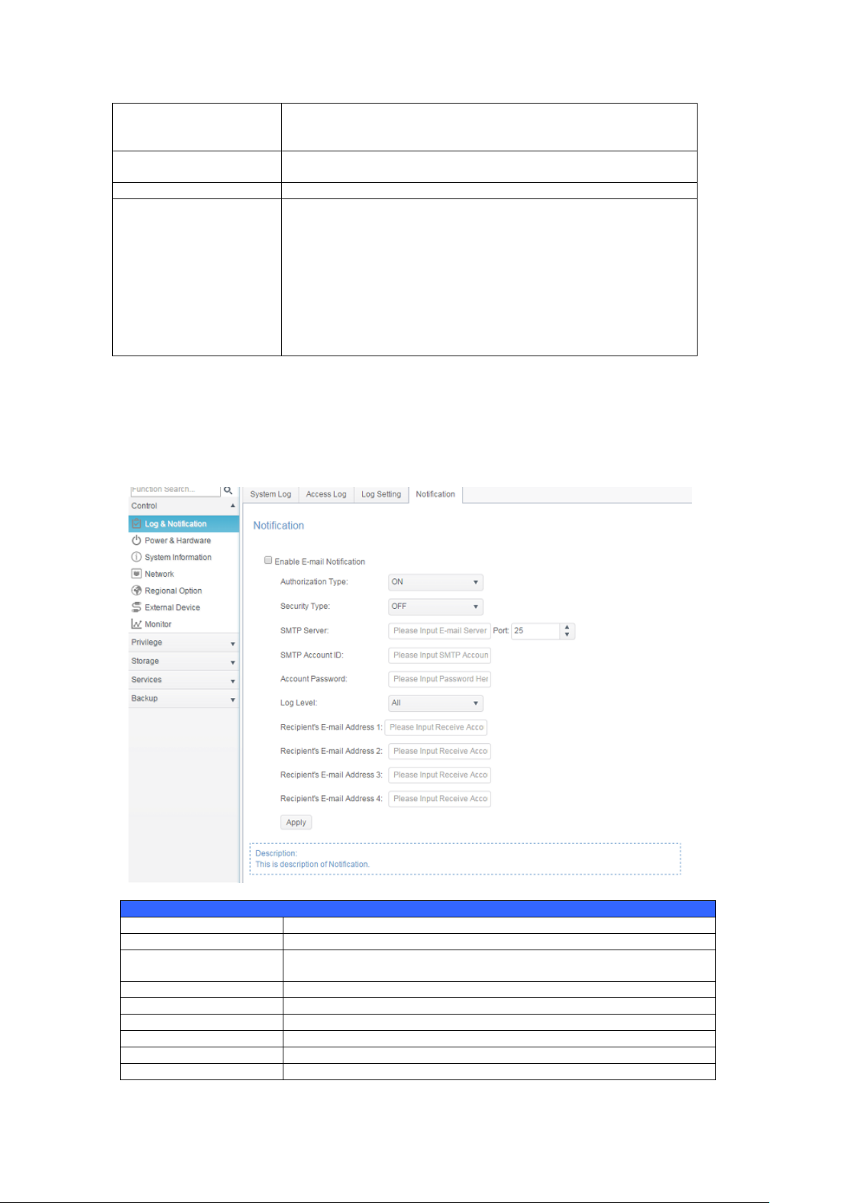
Notification Configuration
Item
Description
Email Notification
Enable or disable email notifications of system problems.
Authentication Type
Select the SMTP Server account authentication type from drop
down list.
Security Type
Select the security type while mail has sent out
SMTP Server
Specifies the hostname/IP address of the SMTP server.
Port
Specifies the port to send outgoing notification emails.
SMTP Account ID
Set the SMTP Server Email account ID.
Account Password
Enter a new password.
Log Level
Select the log level to send the e-mail out.
Notification
From log and notification, choose the Notification item, and the Notification
Configuration screen will appear. This screen lets you have Thecus IP storage
notify you in case of any system malfunction. Press Apply to confirm all settings.
See following table for a detailed description of each item.
27
Page 28
Sender’s E-mail
Address
Set senders email address to send email notifications.
HELO/EHLO Domain
Name
Specified valid HELO/EHLO domain name
Receiver’s E-mail
Address (1,2,3,4)
Add one or more recipient’s email addresses to receive email
notifications.
NOTE
Consult with your mail server administrator for email server
information.
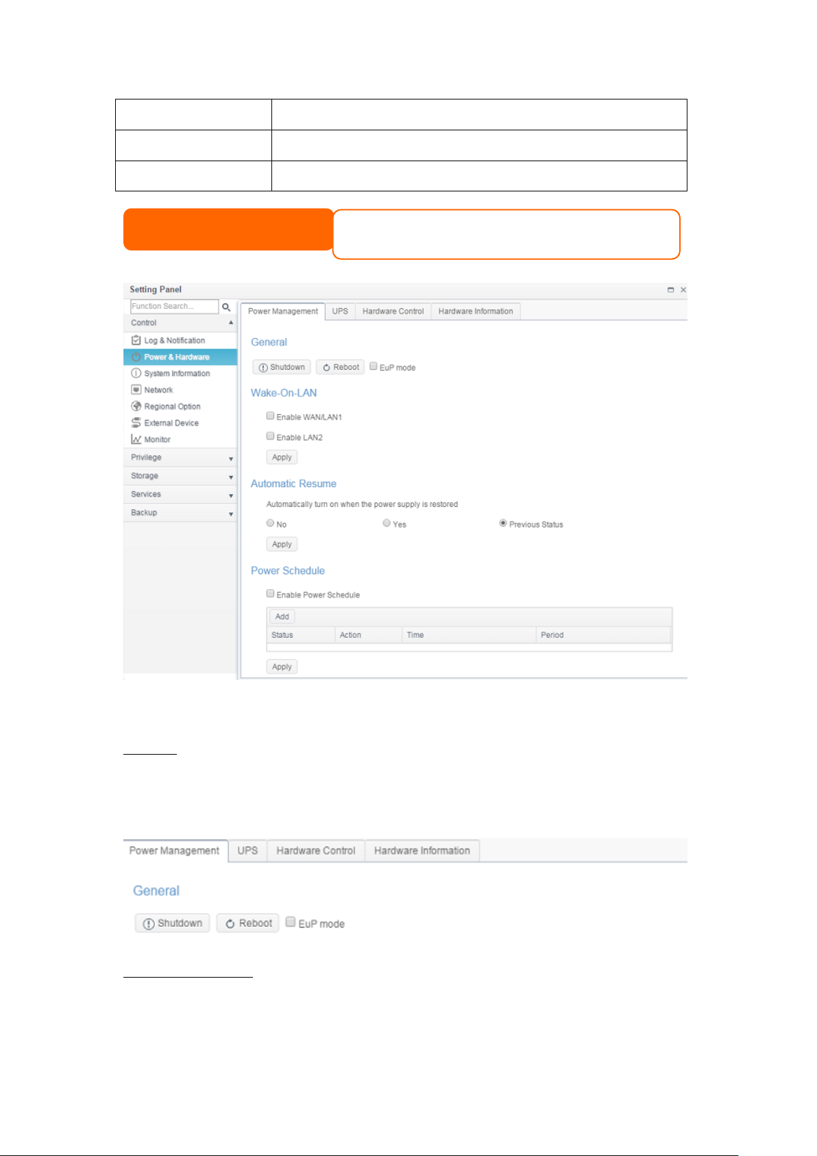
Power & Hardware
Power Management
General
Press Reboot to restart the system or Shutdown to turn the system off.
The option of Eup mode could help to lower system power consumption.
However, once it has enabled the Wake-On-Lan
, Power Schedule will be disabled automatically to meet Eup standard.
Automatic Resume
Thecus IP storage allows users to setup in 3 different modes while power cut
resume.
28
Page 29
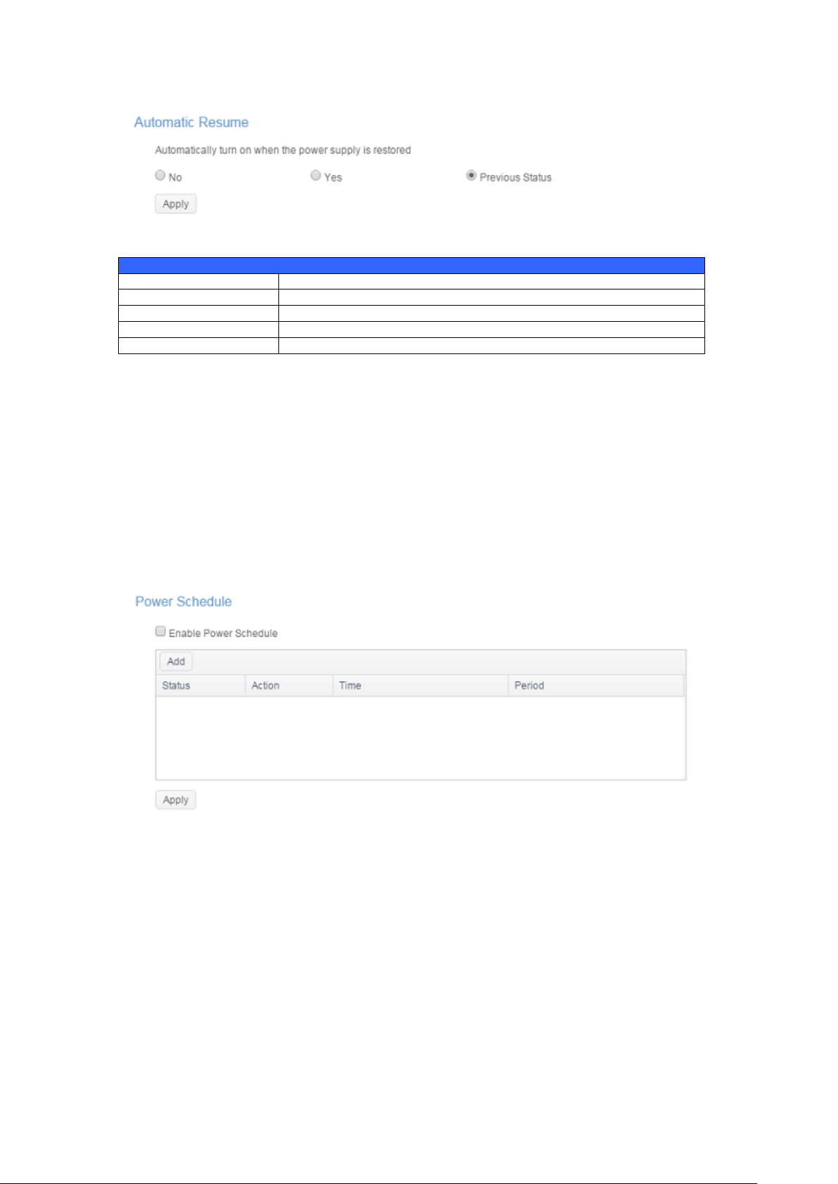
Automatic Resume
Item
Description
No
Choose No to keep system off after power cut resume
Yes
Choose Yes to have system on after power cut resume
Previous Status
Keep former state of system while power cut resume
Apply
Click Apply to save changes.
Power Schedule
Using the Thecus IP storage Power Management, you can save energy and money
by scheduling the Thecus IP storage to turn itself on and off during certain times
of the day.
To designate a schedule for the Thecus IP storage to turn on and off, first enable
the feature by checking the Enable Power Schedule checkbox.
Then, click Add to add desired time for system power on or off.
Finally, click Apply to save your changes.
Example - Monday: On: 8:00; Off: 16:00
System will turn on at 8:00 AM on Monday, and off at 16:00 on Monday. System
will turn on for the rest of the week.
If you choose an on time, but do not assign an off time, the system will turn on
and remain on until a scheduled off time is reached, or if the unit is shutdown
manually.
Example - Monday: On: 8:00
System will turn on at 8:00 AM on Monday, and will not shut down unless
powered down manually.
You may also choose two on times or two off times on a particular day, and the
system will act accordingly.
29
Page 30
Wake-up On LAN Configuration
Item
Description
WAN/LAN1
Enable or Disable WOL service from WAN/LAN1
LAN2
Enable or Disable WOL service from LAN2
Apply
Click Apply to save changes.
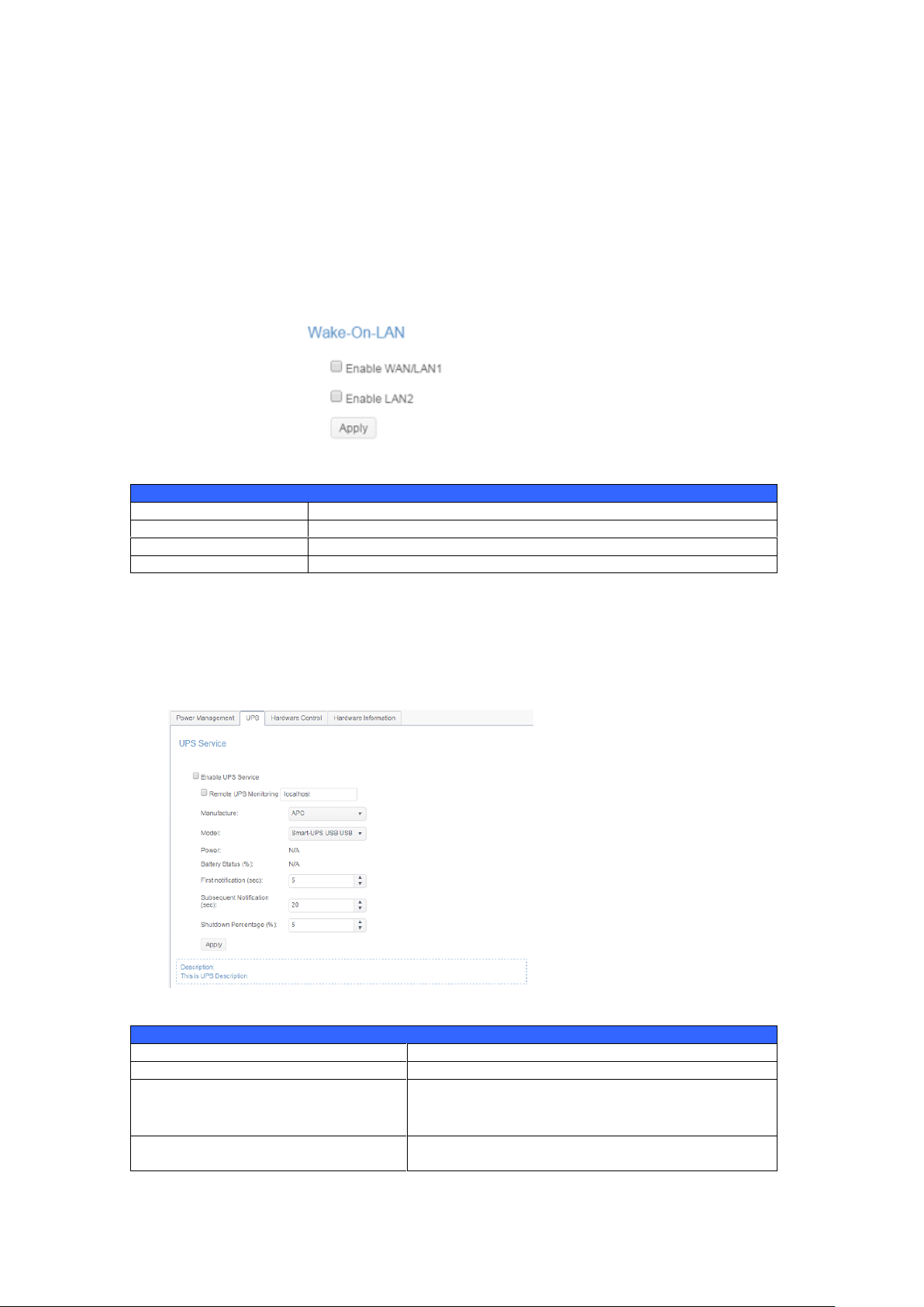
UPS Setting
Item
Description
UPS Service
Enable or disable UPS monitoring.
Remote UPS Monitoring
Checked to enable remote UPS monitoring. And
input the IP address of the NAS that the UPS
device is connected to via USB.
Manufacturer
Choose the UPS manufacturer from the
dropdowns.
Example - Monday: Off: 8:00; Off: 16:00
System will turn off at 8:00 AM on Monday. System will turn off at 16:00 PM on
Monday, if it was on. If the system was already off at 16:00 PM on Monday,
system will stay off.
Wake-On-LAN
The Thecus IP storage has the ability to be awoken from sleep mode via
WAN/LAN1 or LAN2 port.
Click on associated NIC interface to Enable or Disable Wake-On-LAN.
UPS
Thecus IP storage supports Uninterrupted Power Source through USB
interface. Make the changes of UPS Setting and press Apply to confirm
changes.
See the following table for a detailed description of each item.
30
Page 31

Model
Choose the UPS model number from the
dropdowns.
Battery Status
Current status of the UPS battery
Power
Current status of the power being supplied to the
UPS
First notification (sec)
Delay between power failure and first notification
in seconds.
Subsequent notifications (sec)
Delay between subsequent notifications in
seconds.
Shutdown percentage (%)
Amount of UPS battery remaining before system
should auto-shutdown.
Apply
Press Apply to save your changes.
Hardware Control
The system buzzer can be Enabled/Disabled by clicking the check box. Check
to enable system buzzer when any error occurs or disable to mute the system.
31
Page 32

System Information
System Status
Item
Description
Model
Model name
Version
Current FW version
CPU Activity
Displays current CPU workload of the Thecus IP storage.
Memory Activity
Display current memory workload of the Thecus IP storage
CPU Temperature
Displays current CPU Temperature.
System
Temperature/1
Displays current System temperature from 2 positions
System Fan Speed
Displays the current status of the system fan.
Up Time
Shows how long the system has been up and running.
Network Information (Global parameter)
Item
Description
Host name
Host name that identifies the Thecus IP storage on the network.
Domain name
Specifies the domain name of Thecus IP storage.
Link speed
Display associated NIC port link speed.
Link status
Display associated NIC port link status.
MAC address
MAC address of the network interface.
IPv4 IP address
IP address of associate NIC interface in IPv4.
System Status
This screen provides basic system status information.
Network Status
This screen provides basic system network status and information.
32
Page 33

IPv6 IP address
IP address of associate NIC interface in IPv6.
Service Status
Item
Description
AFP Status
The status of the Apple Filing Protocol server.
NFS Status
The status of the Network File Service Server.
SMB/CIFS Status
The status of the SMB/CIFS server.
FTP Status
The status of the FTP server.
TFTP Status
The status of the TFTP server.
Rsync Status
The status of the Rsync server.
UPnP Status
The status of the UPnP service.
SNMP
The status of the SNMP service.
Service Status
This screen provides basic service status information.
33
Page 34

Hardware Information
Click on Hardware Information, this will display the related HW details for the
associated model. Below is an example of the information for a Thecus N5810.
Network
From the Control menu, choose Network, and the Networking Configuration
screen will appear. This screen displays the network parameters of the global
setting and available network connection. You may change any of these items
and press Apply to confirm your settings. See a description of each item in the
following table:
34
Page 35

Network Setting
WAN/LAN Setting:
The available system network ports are coming from embedded system ports.
Therefore, the screen shown above is an example of a Thecus N5810 with 2 on
board GbE NIC.
To modify port setting, please click on Edit with the associated network port. The
setting screen will appear, it can be configured for basic setting, DHCP server and
VLAN.
Basic Setting:
35
Page 36

Basic Setting
MAC address
MAC address of the network interface.
IP
IP address of associate NIC interface.
Device speed
Display associated NIC port link speed.
Link status
Display associated NIC port link status.
Jumbo Frame
Input Jumbo Frame rate from drop down list, default is 1500
Note
Input the description of associated network port if any
IPv4/IPv6
Setting IP address from manual input or DHCP server .
Mode
It can choose a static IP by manually input or Dynamic IP from DHCP
server.
IP address
Input IP address if manually input has selected or displayed by granted
from DHCP server
Netmask
Input netmask if manually input has selected or displayed by granted
from DHCP server
Gateway
Input gateway if manually input has selected or displayed by granted from
DHCP server
DHCP Configuration
Item
Description
Enable IPv4/IPv6 DHCP
Server
Enable or disable the IPv4/IPv6 DHCP Server to automatically
assign IP address to PCs connected to associate NIC
interface.
Start IP (IPv4)
Specifies the lower IP address of the DHCP range.
End IP in (IPv4)
Specifies the highest IP address of the DHCP range.
WARNING
Most faster Ethernet (10/100) Switches/Routers do not support Jumbo Frame and will not be
able to connect to your Thecus NAS after Jumbo Frame is turned on.
NOTE
• Only use Jumbo Frame settings when operating in a Gigabit environment
where all other clients have Jumbo Frame Setting enabled.
• Proper DNS setting is vital to networks services, such as SMTP and NTP.
DHCP Server:
The network port of Thecus IP storage can be acted as DHCP server if associated
NIC has been set-up to a static IP. Please fill in the fields to complete setting.
36
Page 37

Netmask(IPv4)
Specifies netmask for the DHCP server service.
Default Gateway (IPv4)
Specifies gateway for the DHCP server service.
DNS Server 1,2,3 (IPv4)
Displayed the DNS server IP address.
Prefix (IPv6)
Specifies prefix
Prefix Length (IPv6)
Specifies prefix length
WARNING
The IP address of associated NIC should not be in the range of the Start
IP address and End IP address (IPv4).
VLAN:
Each NIC is capable of VLAN support. To enable VLAN, simply click the check box
and input the VLAN ID (VLAN ID can be any digital number). The system with the
same VLAN ID will become a Virtual LAN group to allow more specific
communication among members.
37
Page 38

Quality of Service
Quality of Service Configuration
Enable the Rule
Checked the box to enable defined rule.
Network Interface
Select network interface from drop down list.
Service List
Select desired service to have QoS served
User Defined
Other than pre-defined service list, user defined service is
allowed.
Service Name
Input user defined service name
Protocol and Ports
Input user defined protocol from drop down list and associated
ports will be used
Protocol
List associated protocol of selected service.
Ports
List associated port number of selected service.
Guaranteed (KB/s)
Input MUST of throughput for associated service.
Maximum (KB/s)
Input maximum of throughput for associated service
Thecus IP storage is capable for QoS (Quality of Service) by supported services.
The bandwidth will give by the order from QoS list once the overall bandwidth
required is larger than the physical number.
To setup QoS, simply Enable QoS and then click ‘Add” on QoS screen. The screen
will appear as below.
To modify, delete or change priority of created QoS service, select desired service
from service list then click required activities. Carry on for necessary modification
to modify by click “Edit” or click on “Move Up” or “Move Down” to change priority.
The Delete the rule button can be found on left hand bottom corner after go into
“Edit” screen.
38
Page 39

DDNS
Item
Description
DDNS Service
Enable or disable DDNS service.
Register
Choose the service provider from the drop down list
User name
Input user name with DDNS registry.
Password
Input password with DDNS registry.
Domain name
Input domain name with DDNS registry.
Apply
Click “Apply” to confirm the changes.
DDNS
DDNS Support:
To set up a server on the Internet and enable the users to connect to it easily, a
fixed and easy-to remember host name is often required. However, if the ISP
provides only dynamic IP address, the IP address of the server will change from
time to time and is difficult to recall. You can enable the DDNS service to solve
the problem.
After enabling the DDNS service of the NAS, whenever the NAS restarts or the IP
address is changed, the NAS will notify the DDNS provider immediately to record
the new IP address. When the user tries to connect to the NAS by the host name,
the DDNS will transfer the recorded IP address to the user.
The NAS supports the DDNS providers:
DyDNS.org(Dynamic DNS),DyDNS.org(Custom DNS),DyDNS.org(Static DNS),
www.zoneedit.com,www.no-ip.com.
A description for each item as following:
39
Page 40

Time
Item
Description
System Time
The current system date and time
Time Zone
Sets the system time zone.
Sync with NTP Server
Select NTP server from drop down list to sync up system time
Date
Sets the system date manually.
Time
Sets the system time manually.
Apply
Click Apply to save changes.
WARNING
If an NTP server is selected, please make sure your Thecus IP storage has
been setup to access the NTP server.
Regional Option
Date/Time
From the Regional Option menu, choose the Date/Time item and the Time
Settings screen appears. Set the desired Date, Time, and Time Zone. You can
also elect to synchronize the system time on Thecus IP storage with an NTP
(Network Time Protocol) Server.
See the following table for a detailed description of each item:
40
Page 41

NTP Service
The Thecus IP storage can also provide NTP service. You can also elect to
synchronize the system time on Thecus IP storage with an NTP (Network Time
Protocol) Server. To do this, simply click on NTP service button to enable it.
41
Page 42

External Device
Printer Information
Item
Description
Printer Name
The default is usb-printer. It can be changed by select printer
then click on Edit to modify it.
Manufacturer
Displays the name of the USB printer manufacturer.
Model
Displays the model of the USB printer.
Printer job in Queue
Displays the print job in queue of the USB printer.
NOTE
• For example to setup attached USB printer on your Windows 7
environment. Please use http://<NAS IP address>:631/printers/printer
name The default printer name is usb-printer or use the one has been
External HDD
From the External Devices menu, choose the External HDD, and the External
HDD screen will appear. This screen provides the information about the external
HDDs have connected to this system.
Printer
From the External Devices menu, choose the Printer item, and the Printer
Information screen will appear. This screen provides the following information
about the USB printer connected to the USB port.
You can configure Thecus IP storage to act as a printer server. That way, all PCs
connected to the network can utilize the same printer.
Monitor
The system monitor is capable to monitor system status including CPU, memory,
hard disk and network.
42
Page 43

To monitor system status, simply click on tab of associated item and the screen
will appear accordingly.
CPU
Memory
43
Page 44

Hard Disk
Network
Firmware Setting
Firmware Setting
From the menu, choose the Firmware Setting item and the Firmware Setting
screen appears.
44
Page 45

System Configuration Management
Item
Description
Backup
Save and export the current system configuration.
Select
Import a saved configuration file to overwrite the current
system configuration.
NOTE
• Check Thecus website for the latest firmware release and release notes.
• Downgrading firmware is not permitted.
WARNING
Do not turns off the system during the firmware upgrade process.
This will lead to a catastrophic result that may render the system inoperable.
NOTE
Backing up your system configuration is a great way to ensure that you can
revert to a working configuration when you are experimenting with new system
settings.
The system configuration you have backed up can only be restored in the same
firmware version. The backup details exclude user/group accounts.
Follow the steps below to upgrade your firmware:
1. Click the Select button to find the firmware file.
2. System will check correctness of selected file and carry on for upgrade
process .
3. The buzzer will beep and the Busy LED will blink until the upgrade is
complete.
Configuration Management
The System Configuration Management is to let you to download or upload
stored system configurations.
See the following table for a detailed description of each item.
45
Page 46

Automatic Upgrade
WARNING
Resetting to factory defaults will not erase the data stored in the hard disks,
but WILL revert all the settings to the factory default values.
The system is defaulted to enable Major upgrade mode for any MUST update. It
also provides the option for Latest upgrade mode, which has Major upgrade
included but also most updated fixes and latest functions.
Click on Check Upgrade Now can let you find out the latest FW version.
Reset to Default
In any case the system needs to set back to factory default, click on Apply on
Reset to Default section to reset Thecus IP storage to factory default settings.
PRIVILEGE
Share Folder
From the PRIVILEGE menu, choose Share Folder, and the Shared Folder
screen will appear. This screen allows you to create and configure folders on the
Thecus IP storage volume.
46
Page 47

Adding Folders
Add Folder
Item
Description
RAID ID
RAID volume where the new folder will reside.
Folder Name
Enter the name of the folder.
Description
Provide a description the folder.
Browseable
Enable or disable users from browsing the folder contents. If
Yes is selected, then the share folder will be browseable.
Public
Admit or deny public access to this folder. If Yes is selected,
then users do not need to have access permission to write to
this folder. When accessing a public folder via FTP, the behavior
is similar to anonymous FTP. Anonymous users can
upload/download a file to the folder, but they cannot delete a
file from the folder.
Read Only
Define only allowed to read from associate but not write into.
On the Shared Folder screen, click on the Create button and the Create Folder
screen appears. There are four sub-items related folder creation setting. Please
fill in necessary information then press Apply to complete folder creation.
General Settings:
Please input required information to complete general setting of folder creation.
47
Page 48

Apply
Press Apply to create the folder.
User ACL setting
Item
Description
Deny
Denies access to users who are displayed in this column.
Read Only
Provides Read Only access to users who are displayed in this
column.
Writable
Provides Write access to users who are displayed in this
column.
NOTE
Folder names are limited to 60 characters. Systems running Windows 98 or
earlier may not support file names longer than 15 characters.
User ACL:
On the Folder Create screen, press the User ACL button, and the User ACL
setting screen will appear. This screen allows you to configure access to the
specific folder for users. From the left hand column user lists then choose Deny,
Read Only, or Writable to configure their access level. Press the Apply button
to confirm your settings.
Group ACL:
On the Folder Create screen, press the Group ACL button, and the Group ACL
setting screen appears. This screen allows you to configure access to the specific
folder for groups. From the left hand column group lists then choose Deny, Read
Only, or Writable to configure their access level. Press the Apply button to
confirm your settings.
48
Page 49

Group ACL setting
Item
Description
Deny
Denies access to groups who are displayed in this column.
Read Only
Provides Read Only access to groups who are displayed in this
column.
Writable
Provides Write access to groups who are displayed in this
column.
NOTE
If one user has belonged to more than one group with different privilege,
then the priority of the privilege will be as followed:
Deny > Read Only > Writable
NFS:
To allow NFS access to the share folder, enable the NFS Service, and then set up
hosts with access rights as well as related options.
49
Page 50

NFS Share
Item
Description
Hostname
Enter the name or IP address of the host
Privilege
Host has either read only or writeable access to the folder.
OS Support
There are two selections available:
● Unix / Linux System
● AIX (Allow source port > 1024)
Choose the one which best fits your needs.
ID Mapping
There are three selections available:
● Guest system root account will have full access to this
share (root:root).
● Guest system root account will be mapped to
anonymous user (nobody:nogroup) on NAS.
● All user on guest system will be mapped to anonymous
user (nobody:nogroup) on NAS.
Choose the one which best fits your needs.
Sync / Async
Choose to determine the data “Sync” at once or “Async” in
arranged batch.
Apply
Click to save your changes.
Modify/Remove Folders
On the existed Folder list, click on desired Folder then the associated menu
items will appear.
50
Page 51

NOTE
The Snapshot item will appear only if:
3. The system RAID volume is selected btrfs file system.
4. The folder is user created not system default.
Edit & ACL:
Click on the Edit & ACL buttons, there are five sub-items related folder
modification that can be choose if the associated folder has ACL defined. Or ACL
related tabs won’t appear and it is known as public folder.
General Settings:
The only item can’t be changed is folder belonging with associated RAID volume.
With others, make any changes if required.
User ACL (ACL folder only):
It is allowed to change access user list of associated folder.
Group ACL (ACL folder only):
It is allowed to change access group list of associated folder.
51
Page 52

NFS:
It is allowed to change the existing NFS access setting or create a new one. To
modify existing setting, click on from list then press Edit tab,
Or click on Add tab to create new access setting.
Subfolder ACL:
Other than folder level access control support, Thecus IP storage is capable for
sub-folder ACL. To setup sub-folders ACL, click on Subfolder ACL tab and screen
shows as below.
The left hand pane is the subfolders list for the associated parent folder. Click on
desired subfolder and the right hand pane will appear and have system’s user and
group. Make necessary changes for user or group access right of associated
subfolder. Please do remember to click on Save ACL tab once setting completed.
52
Page 53

NOTE
The ACL can only be set for share and sub-folders level, not for files.
WARNING
All the data stored in the folder will be deleted once the folder is deleted.
The data will not be recoverable.
Remove Folder:
Click on Remove Folder tab and associated folder will be deleted from system.
53
Page 54

Local Account
Local User Configuration
Item
Description
Refresh
Press Refresh to reload user list
Create
Press the Create button to add a user to the list of local users.
Edit
Press the Edit button to modify a local user.
Batch Input
Press the Batch Input button and associated screen appear to
allow using batch input of local users.
The Thecus IP storage has built-in user database that allows administrators to
manage user access using different group policies. From the Privilege menu of
Local Account , you can create, modify, and delete users, and assign them to
groups that you designate.
User
From the Local Account menu, choose the User item, and the Local User
Configuration screen appears. This screen allows you to Add, Edit, Remove
and Batch Input local users.
54
Page 55

Create User:
On the User screen, press the Create button and the Create User screen
appears. Follow the wizard and system will lead you to complete the setting.
1. Enter a User ID number or leave it to use the system default value.
2. Tick on check box if this can be acted as administrator.
3. On the Account ID field, enter a name for the User.
4. Enter a User ID number or leave blank to use the system default value.
5. Enter a password in the Password box and re-enter the password in the
Confirm box.
6. Input the user description
7. Input user’s mail address
8. Input user quota or leave it as default for no limitation.
9. Press the Next button to next page.
1. Select which group the user will belong to. Group Members is a list of
groups this user belongs to.
2. Press the Next button to next page.
55
Page 56

1. Set the access right for ACL folders.
2. Checked “Recursive” box if it will apply to all subfolders
3. Press the Next button go to next page.
1. The page has listed user’s information for double check.
2. Press the Create button and the user is created.
56
Page 57

Batch Input:
NOTE
All users are automatically assigned to the ‘users’ group.
The Thecus IP storage can also add users and groups in batch mode. This enables
you to conveniently add numerous users and groups automatically by importing a
simple Microsoft Excel (*.csv) file.
From the User menu, click Batch Input and the Batch User Input Creation
dialogue will appear. To import your list of users and groups, follow these steps:
1. Click on the Select button to locate your Excel (.csv) file.
2. Click Confirm Batch Input to confirm import.
3. Or on the left bottom corner can download sample file to manipulate.
Edit User:
1. Select an existing user from the list.
2. Click on the Edit button, and the User Setting screen appears.
3. Making the changes if need.
57
Page 58
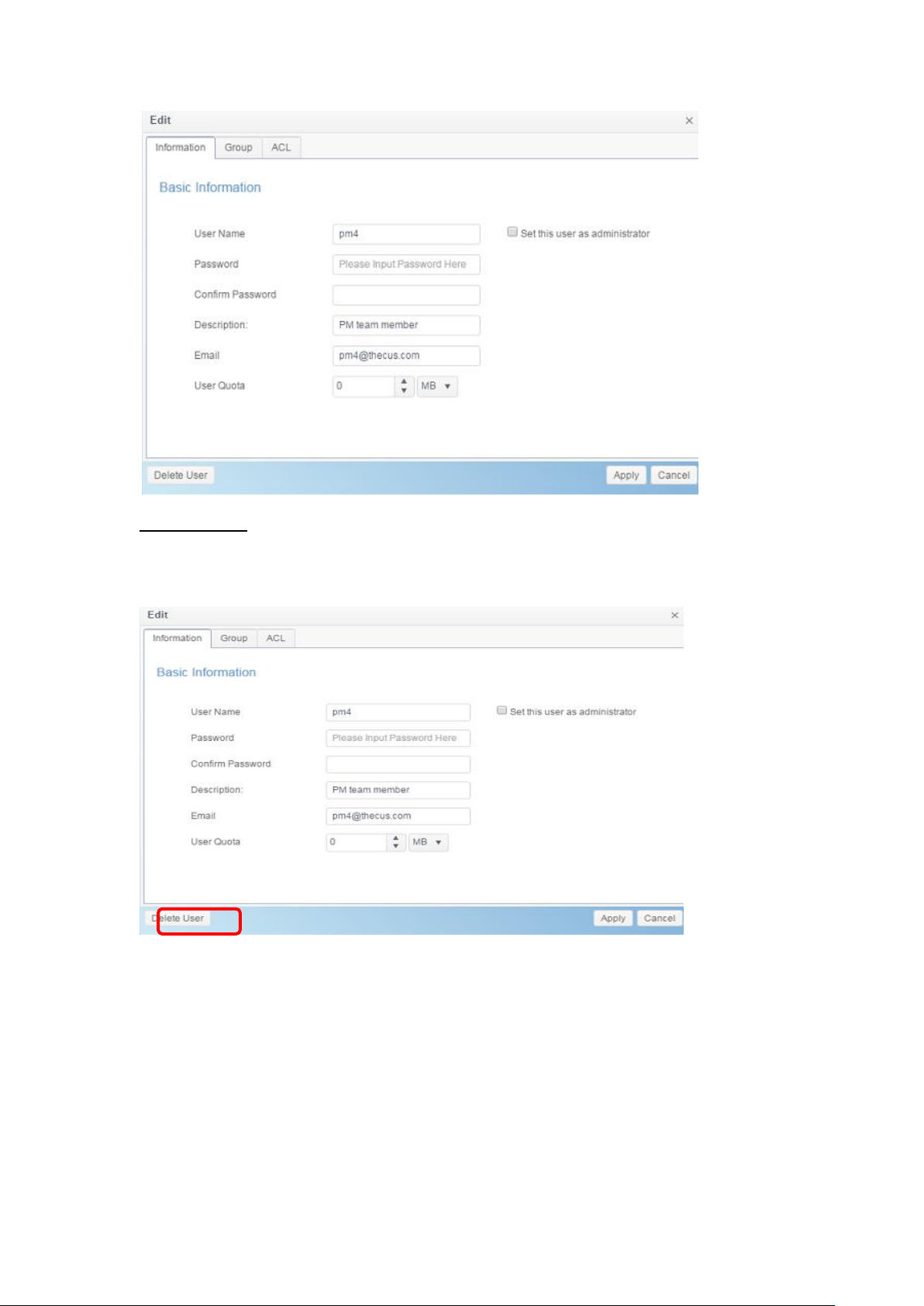
Delete User:
1. Select an existing user from the list.
2. Click on the Delete User button, and the User will remove from system.
58
Page 59

Group
Create Group:
On the Group screen, press the Create button and the Create Group screen
appears. Follow the wizard and system will lead you to complete the setting.
1. Enter a Group ID number or leave it to use the system default value.
2. On the Group Name field, enter a name for the Group.
3. Press the Next button to next page.
59
Page 60

1. Select group members from user list.
2. Press the Next button to next page.
1. Set the access right for ACL folders.
2. Checked “Recursive” box if it will apply to all subfolders
3. Press the Next button to go to next page.
1. The page has listed group’s information for double check.
2. Press the Create button and the group is created.
60
Page 61

Edit Group:
1. Select an existing group from the list.
2. Click on the Edit button, and the Group Setting screen appears.
3. Making the changes if need.
61
Page 62

Delete Group:
1. Select an existing user from the list.
2. Click on the Delete Group button, and the User will remove from system.
User Quota (Btrfs not support)
The Thecus IP storage support local or AD users with storage quota limitations in
each RAID volume of the system. To enable this function, simply click “Enable”,
then apply.
It can click on Start Scan button to have most update of quota usage for every
user and associated RAID volumes.
62
Page 63

Backup & Restore
User and group settings download/upload:
The user and group backup feature allow system users and groups to be backed
up to another location and be restored if needed.
Please note, when restoring previous backup users and groups, the current users
and groups list will be replaced from this restore file’s contents.
ACL backup/restore
The ACL backup and restore feature enables the system ACL (Access Control List)
to be backed up on the RAID volume based to other location and restored if
needed.
ADS
If you have a Windows Active Directory Server (ADS) to handle the domain
security in your network, you can simply enable the ADS support feature; the
Thecus IP storage will connect with the ADS server and get all the information of
the domain users and groups automatically. From the Privilege menu, choose
ADS item and the ADS Setting screen appears. You can change any of these
items and press Apply to confirm your settings.
63
Page 64

ADS/NT Support
Item
Description
Work Group / Domain
Name
Specifies the SMB/CIFS Work Group / ADS Domain Name (e.g.
MYGROUP).
ADS Support
Select Disable to disable authentication through Windows Active
Directory Server.
ADS Server Name
Specifies the ADS server name (e.g. adservername).
ADS Realm
Specifies the ADS realm (e.g. example.com).
Administrator ID
Enter the administrators ID of Windows Active Directory, which
is required for Thecus IP storage to join domain.
Administrator
Password
Enter the ADS Administrator password.
Apply
To save your settings.
A description of each item follows:
To join an AD domain, you can refer
to the figure here and use the
example below to configure the
Thecus IP storage for associated filed
input:
64
Page 65

AD Domain Example
Item
Information
Work Group / Domain
Name
domain
ADS Support
Enable
ADS Server Name
Computer1
ADS Realm
Domain.local
Administrator ID
Administrator
Administrator
Password
***********
LDAP Support
Item
Description
LDAP Service
Enable or Disable LDAP service.
LDAP Server IP
Input LDAP server IP address.
Base Domain
Input base domain information ex. dc=tuned, dc=com, dc=tw
Manager
Input manager’s name.
NOTE
• The DNS server specified in the WAN/LAN1 configuration page should
be able to correctly resolve the ADS server name.
• The time zone setting between Thecus IP storage and ADS should be
identical.
• The system time difference between Thecus IP storage and ADS should
be less than five minutes.
• The Administrator Password field is for the password of ADS (Active
Directory Server) not Thecus IP storage.
LDAP
The LDAP is the other way to authenticate login users who has joined LDAP server,
fill in the LDAP server information and get LDAP authentication started. Please
make sure that the LDAP server has a Samba sam and a POSIX ObjectClass
account.
65
Page 66

Password
Input manager’s password
Apply
Click Apply to save your changes.
Check ObjectClass
Click this checkbox to ensure LDAP server has a Samba sam
and a POSIX account or it may not work properly for LDAP
client authentication.
Storage
Disk & RAID
& RAID and the associated storage information will display. Also the related
setting can be operated from here.
RAID
From the Disk& RAID menu, choose the RAID item and the RAID
Management screen appears.
This screen lists the RAID volumes currently residing in the Thecus IP storage.
From this screen, you can get information about the status of your RAID volumes,
as well as the capacities allocated for data.
66
Page 67

Create a RAID
RAID Configurations
Item
Description
Disk .
Number assigned to the installed hard disks.
Capacity (MB)
Capacity of the installed hard disks.
Model
Model number of the installed hard disks.
Status
Status of the installed hard disks.
Used
If this is checked, current hard disk is aalready part of a RAID
volume.
Spare
If this is checked, current hard disk is designated as a spare for
a RAID volume.
Master RAID
Check a box to designate this as the Master RAID volume. See
the NOTE below for more information.
Stripe Size
This sets the stripe size to maximize performance of sequential
files in a storage volume. Keep the 64K setting unless you
require a special file storage layout in the storage volume. A
larger stripe size is better for large files.
Data Percentage
The percentage of the RAID volume that will be used to store
data.
Create
Press this button to configure a file system and create the RAID
storage volume.
On the RAID Information screen, press the Create button to go to the RAID
Volume Creation screen. In addition to RAID disk information and status, this
screen lets you make RAID configuration settings.
Using Create RAID, you can select stripe size, choose which disks are RAID
disks or the Spare Disk. .
To create a RAID volume, follow the steps below:
1. On the Select Disk screen, select available disks for the RAID volume
member(s).
2. Set the RAID storage space as JBOD, RAID 0, RAID 1, RAID 5, RAID 6,
RAID 10, RAID 50 and RAID 60 (depends on how many disks has
installed into system)— see Appendix B: RAID Basics for a detailed
description of each.
67
Page 68

3. Choose spare disk for associated RAID volume if applicable.
4. Specify a RAID Name.
68
Page 69

5. If this RAID volume is meant to be the Master RAID volume, tick the
NOTE
In a multiple RAID configuration, one RAID volume must be designated as the
Master RAID volume. The Master RAID volume will store all installed modules.
If the Master RAID is changed to another location (i.e. assigning volume 2 to
be the Master RAID volume after volume 1 had been previously assigned),
then all modules must be reinstalled. In addition, all system folders that were
contained on the Master RAID volume will be invisible. Reassigning this
volume to be the Master RAID will make these folders visible again.
Master RAID checkbox.
6. Selected whether the RAID volume will be encrypted or not.
The RAID volume can protect data by using RAID Volume Encryption
function to prevent the risk of data exposure. To activate this function, the
Encryption option needs to be enabled while the RAID is created and
followed by a password input for identification. Also, an external writable
USB disk plugged into any USB port on the system is required to save the
password you have entered while the RAID volume is being created. See
the screenshot below for details.
69
Page 70

After the RAID volume has been created, you may remove the USB disk until
NOTE
With RAID volume encryption enabled, the system performance will go
down.
WARNING
Please keep your USB disk in a safe place and also backup the
encrypted key.
There is no way to rescue data back if the
key is lost.
NOTE
We recommend using the “Quick RAID” setting only if the hard disks are
brand new or if no existing partitions are contained.
the next time the system boots. The RAID volume cannot be mounted if the
USB disk with the encryption key isn’t found in any system USB port when
the volume is accessed. To activate the encrypted volume, plug the USB disk
containing the encryption key and into any system USB port.
We strongly recommended copying the RAID volume encryption key to a
safe place. You can find the encryption key file from the USB disk in the
following format:
(RAID volume created date)_xxxxxx.key
RAID volumes with encryption enabled will be displayed with a key lock
symbol next to volume ID name.
7. Quick RAID — Enabling the quick RAID setting is going to enhance RAID
creation time.
70
Page 71

Level
Model
JBOD
RAID 0
RAID 1
RAID 5
RAID 6
RAID 10
RAID 50
RAID 60
N2350 series
N4350 series
RAID Levels
Level
Description
JBOD
The storage volume is a single HDD with no RAID support. JBOD
requires a minimum of 1 disk.
RAID 0
Provides data striping but no redundancy. Improves
performance but not data safety. RAID 0 requires a minimum of
2 disks.
RAID 1
Offers disk mirroring. Provides twice the read rate of single
disks, but same write rate. RAID 1 requires a minimum of 2
disks.
RAID 5
Data striping and stripe error correction information provided.
RAID 5 requires a minimum of 3 disks. RAID 5 can sustain one
failed disk.
NOTE
Single volume size supported:
ext3 8TB
XFS 48TB
ext4 36TB
btrfs 16EB
NOTE
Building a RAID volume may be time consuming, depending on the size
of hard drives and RAID mode. In general, if the RAID volume building
process is up to “RAID Building”, then the data volume is accessible.
WARNING
Creating RAID destroys all data in the current RAID volume. The data will
be unrecoverable.
8. Specify a stripe size — 64K is the default setting.
9. Specify size for “Bytes per inode” if ext3/ext4 has selected. The default
value is Auto and it has no need to change for general use.
10. Select the file system you would like to have for this RAID volume. The
selection is available from ext3, XFS, ext4 and btrfs(N2350/N4350 not
supported).
11. Press Create Finished to build the RAID storage volume.
RAID Level
You can set the storage volume as JBOD, RAID 0, RAID 1, RAID 5, RAID 6,
RAID 10, RAID 50 and RAID 60 (Depend on Model and how many disks
has been installed).
RAID configuration is usually required only when you first set up the device. A
brief description of each RAID setting follows:
71
Page 72

RAID 6
Two independent parity computations must be used in order to
provide protection against double disk failure. Two different
algorithms are employed to achieve this purpose. RAID 6
requires a minimum of 4 disks. RAID 6 can sustain two failed
disks.
RAID 10
RAID 10 has high reliability and high performance. RAID 10 is
implemented as a striped array whose segments are RAID 1
arrays. It has the fault tolerance of RAID 1 and the performance
of RAID 0. RAID 10 requires 4 disks. RAID 10 can sustain two
failed disks.
WARNING
If the administrator improperly removes a hard disk that should not be
removed when RAID status is degraded, all data will be lost.
WARNING
Remove RAID destroys all data in the selected RAID volume. The data
will be unrecoverable.
Edit RAID
1. Select an existing RAID volume from the list.
2. Click on the Edit button, and the RAID volume setting screen appears.
3. Making the changes such as RAID name or role of master RAID if needed.
Remove RAID
1. Select an existing RAID volume from the list.
2. Click on the Remove RAID button from left bottom corner, A confirmation
screen will appear.
3. Confirm with click “OK” to complete the “Remove RAID” operation.
Click to remove the RAID volume. All user data and iSCSI created in the selected
RAID volume will be deleted.
72
Page 73

Expanding a RAID
To expand a RAID 1, RAID 5, or RAID 6 volume, follow the steps below:
1. Replace one of the hard drives in the RAID volume and allow it to
automatically rebuild.
2. Once rebuilt, you can continue to replace any remaining disks in the RAID
array.
3. When you are done replacing hard drives, click on RAID volume that is
going to expand capacity. System will have additional tab “Space
Expansion” appear if associated RAID volume is capable for expansion.
4. On the RAID Configuration screen, click Space Expansion.
File System Check
The File System Check allows you to perform a check on the integrity of your
disks’ file system.
To perform File System Check, select RAID volume from RAID Volume list and the
tab File System Check will appear. Click on File System Check button to start
the task. From the screen, it will display FSCK check time and checking status.
Migrating a RAID
Once a RAID volume has been created, you may want to move it to other
physical drives or change the RAID array all together. To migrate a RAID 1, RAID
5 or RAID 6 volume, follow the steps below:
73
Page 74

NOTE
Migrating a RAID volume could take several hours to complete
The RAID migration feature is available only when it is
configurable.
NOTE
The migration scheme below is based on Thecus
IP Storage product’s maximum possible
combination. For other model which supports less
HDD, please refer to the web UI while RAID
migration operates.
1. Select RAID volume which is going to execute RAID Migration.
2. Press Edit to bring up management screen.
3. Choose Grow to have all installed disks listed included used and unused.
4. Select from unused disk then click OK, the system will bring up available
options to choose from.
5. Confirm the setting, then system will begin migrate the RAID volume.
Here is a list of limitation with RAID level migration function:
1. During RAID level migration, it is not permitted to reboot or shutdown
system.
2. For RAID migration from R1 to R5 or R1 to R6, all services will restart
and “iSCSI” volume will be in read only mode but read/write of the “user
data” will be possible during the operation.
74
Page 75

To
From
RAID 0
RAID 5
RAID 6
RAID
1
[RAID 1] HDDx2 to [RAID 5] HDDx3
[RAID 1] HDDx2 to [RAID 5] HDDx4
[RAID 1] HDDx3 to [RAID 5] HDDx4
[RAID 1] HDDx2 to [RAID 6] HDDx4
[RAID 1] HDDx3 to [RAID 6] HDDx4
RAID
5
X
[RAID 5] HDDx3 to [RAID 5] HDDx4
[RAID 5] HDDx3 to [RAID 6] HDDx4
Below is a table listing of possible RAID migration schemes:
Disk
Disk & RAID talked hard disks basic information, used status and progress while
perform bad block scan.
S.M.A.R.T :
75
Page 76

S.M.A.R.T. Information
Item
Description
Model
Model name of the installed hard disk.
Serial Number
Serial number of the installed hard disk
Sector Size
Sector size of the installed hard disk
Rotation Rate
Rotation speed of the installed hard disk
Temperature (Celsius)
The current temperature of the installed disk in degree Celsius
Uptime(Hour)
Count of hours in power-on state. The raw value of this
attribute shows total count of hours (or minutes, or seconds,
depending on manufacturer) in power-on state.
1. Select a disk from the list.
2. Click on S.M.A.R.T. tab to perform.
Once clicking on S.M.A.R.T., system will display the basic hard disk information
and status. Based on S.M.A.R.T. status, system will give the healthy condition for
reference. Please see below for details.
For more technical S.M.A.R.T. information, please click on Detail.
76
Page 77

You may also like to perform a disk SMART test, simply click “Self Test” to start
the SMART test. The result is only for reference and the system will not take any
action from its results.
There are “Fast Test” or ‘Full test” can be choose from.
Bad Block Scan:
1. Select a disk from the list.
2. Click on Start Scan Block button to perform.
3. Click again to stop bad block scanning.
Global Hot Spare:
Click on installed hard disk but at unused status and the “Global Hot Spare” tab
will appear. Check on the button to have associated hard disk as spare disk.
77
Page 78

Spin Down
For disks installed into system, there is default 30 minutes to spin down if no disk
activities have been detected. However, the spin down duration can be either
turned off or extended. Select from drop down option to make choice.
Disk Security
Thecus IP storage support Disk Security which could perform disk lock capability
of disk itself. Click on “Disk Security” from category Disk & RAID and the installed
disks list will appear. The disk drive which is capable for disk-security will have
check box available to operate further. Please see below:
To setup available disk-security drive, please click on check box then “Set
Password” tab will appear. Click on “Set Password” to have associated disk with
Disk-Security enabled, please do install USB disk and the password will store on it
or it will have an error message to notify you.
78
Page 79

NOTE
The disk to enable Disk-Security setting is
only available while disk is unused
The USB disk which has contained password
need to plug-in on system once associated
disk with Disk-Security enabled is part of
RAID member during system power on.
Without enable Disk-Security on installed
disk, it is just like normal disk
Need to install USB disk on
system, password will store on it.
To change the state of enabled Disk-Security disk, click on associated disk (MUST
in unused) and the available function tab will appear.
79
Page 80

Model
N2350 series
N4350 series
Allowed iSCSI
volume
25
Other than Set Password as mentioned above, the Disk Security can be disabled
by clicking on ‘Disable Disk Security” and the disk can be erased by clicking on
“Erase Disk” if correct password has been inputted.
iSCSI
You may specify the space allocated for iSCSI. See the table below to view the
allowed iSCSI target number per system:
iSCSI List
Add iSCSI Target
To add iSCSI target volume, click Add from iSCSI List and associated screen will
appear.
80
Page 81

NOTE
Be sure the iSCSI target volume has been enabled
or it will not list out while using Initiator to get
associated iSCSI target volumes.
To allocate space for an iSCSI target on the current RAID volume, follow the
steps below:
1. Select desired RAID volume from its drop down list to have iSCSI target
created.
2. Enter a Target Name. This will be used by the Stackable NAS function
to identify this export share.
3. Choose the current year from the Year dropdown.
4. Choose the current month from the Month dropdown.
5. Enable the iSCSI Target Volume by selecting Enable.
81
Page 82

Click Next
NOTE
The iSCSI target volume creation will associate at
least one LUN together. It can be assigned either
“Thin-Provisioning” or “Instant Allocation”.
6. Choose Authority Type to enable CHAP authentication or None.
7. If you’ve enabled CHAP authentication, enter a username and a
password. Confirm your chosen password be reentering it in the
Password Confirm box.
Click Next
8. Enter a LUN Name.
9. When iSCSI target volume has been created, the LUN ID is configurable
from 0 to 254 with a default of the next available number in ascending
numerical order. The LUN ID is unique and cannot be duplicated.
10. Designate the capacity for associate LUN.
11. Choose Thin-Provision or Instant Allocation
12. Choose [ 4K ] block size to have iSCSI target volume over 2TB barrier or [ 512
Bytes ] block size in some application needed.
82
Page 83

Click Next
13. It will display the setting for associated iSCSI target creation. Click Finish
to create the iSCSI volume.
83
Page 84

Create iSCSI Volume
Item
Description
iSCSI Target Volume
Enable or Disable the iSCSI Target Volume.
Target Name
Name of the iSCSI Target. This name will be used by the
Stackable NAS function to identify this export share.
iqn_Year
Select the current year from the dropdown.
Iqn_Month
Select the current month from the dropdown.
Authentication
You may choose CHAP authentication or choose None.
Username
Enter a username.
Password
Enter a password.
Password Confirm
Reenter the chosen password
Mutual CHAP
With this level of security, the target and the initiator
authenticate each other.
Username
Enter a username.
Password
Enter a password.
Password Confirm
Reenter the chosen password
RAID ID
ID of current RAID volume.
LUN Allocation
Two modes can be choose from:
Thin-provision:iSCSI thin-provisioning shares the
available physical capacity to multiple iSCSI target
volumes. It allows virtual capacity to be assigned to targets
prior to adding physical space when it has run out.
Instant Allocation: Allocate available physical
capacity to iSCSI target volumes.
LUN Name
Name of the LUN.
Unused
Unused space on current RAID volume.
Allocation
Percentage and amount of space allocated to iSCSI
volume.
LUN ID
Specific Logic unit ID number.
iSCSI Block size
The iSCSI block size can be set under system advance
option, default is 512 Bytes.
[ 4K ] block size while more than 2TB capacity will be
configured in Windows XP.
[ 512 Bytes ] block size for application like VMware etc.
Advance Option
There are available options for the user to operate Thecus IP storage associated
with iSCSI setting. The details are listed in the following screenshot. If the
options are modified, the system will need to reboot for the changes to take place.
84
Page 85

Max Connections
The maximum number of iSCSI connections.
Error Recovery Level
The Error Recovery Level (ERL) is negotiated during a leading iSCSI connection
login in traditional iSCSI (RFC 3720) and iSER (RFC 5046).
ERL=0: Session Recovery
ERL=0 (Session Recovery) is triggered when failures within a command,
within a connection, and/or within TCP occur. This causes all of the previous
connections from the failed session to be restarted on a new session by
sending a iSCSI Login Request with a zero TSIHRestart all iSCSI connections
on any failure.
ERL=1: Digest Failure Recovery
ERL=1, only applies to traditional iSCSI. For iSCSI/SCTP (which has its own
CRC32C) and both types of iSER (so far), handling header and data
checksum recovery can be disabled.
ERL=2: Connection Recovery
ERL=2, allows for both single and multiple communication path sessions
within a iSCSI Nexus (and hence the SCSI Nexus) to actively perform
realligence/retry on iSCSI ITTs from failed iSCSI connections. ERL=2 allows
iSCSI fabrics to take advantage of recovery in all regards of transport level
fabric failures, and in a completely OS independent fashion (i.e. below the
host OS storage stack).
initialR2T
InitialR2T is a setting that only really matters over high-latency WAN connections
and perhaps in some exotic situations with synchronous writes to very, very fast
storage.
iSCSI CRC/Checksum
To enable this option, the initiator can connect with “Data digest” and “Header
digest”.
Emulate Write Cache
To enable this option, the performance will increase. .
Modify/Remove iSCSI Target
To modify or remove iSCSI target on the current RAID volume, follow the steps
below:
1. Under the iSCSI List, click on desired iSCSI volume you like to modify or
remove.
85
Page 86

2. Click on Edit and associated screen will appear.
3. Click on Remove Target to remove it or make necessary change then
press Apply to confirm.
4. The associated LUN ID can be changed and also expand LUN capacity from
LUNs tab.
86
Page 87

5. To check the connection for associated LUN, click on Connections.
iSCSI Setting
The iSCSI service can be enabled/disabled globally. If iSCSI service has been
turned off then each individual iSCSI volume will be inaccessible.
NAS Stacking
The Thecus IP storage’s capacity can be expanded even further using the
stackable function. With it, users can expand the capacity of their network
storage systems up to 5 other stack target volumes which are located in different
systems. These can be stacked through single network access like SMB or AFP
acting as a share folder type.
87
Page 88

From the main menu, the NAS Stacking feature is located in iSCSI under
“Storage”. Please refer the figure below for reference.
A. Add a Stack Target Volume
From the figure above, click Create to access the stackable target device
configuration page. Please refer to the figure below:
With the added stack target you can “Enable” or “Disable” the stack target now or
later depending on usage required.
Next, input the target IP address of the stackable device and click the Discovery
Target button. The system will list available target volumes from the inputted IP
address.
88
Page 89

Select Target IQN from drop list whic will be the stacking device after connected.
The Device Folder will become the network share name and will be displayed
through network access such as SMB. You may input Comment to tell the
subject of this stack folder if needed.
For this associated stacking device, you may need to input a valid user name and
password to validate your access rights. If there is no user name and password
needed to access target volume, then leave it blank.
From the figure above, the Device Folder is “kendo02”. The figures below show
the result before and after via Microsoft Network Access when settings have been
completed.
89
Page 90

The Browseable setting is the same method used for setting a system share
folder. It designates whether or not this folder will be visible through web disk.
You may refer to the figure below for reference when Yes and No are selected.
The Public setting will be set the same way as the setting for the system share
folder associated with the ACL permission is. The sample above of Device Folder
“Kendo02” can be found from share folder list.
Click Apply to save your changes.
B. Activate a Stack Target
After your settings have been applied, the system will bring you back to the NAS
Stacking List window as shown below. There is one stack target device that has
been attached into this stack master.
With this newly attached stack target device, you will see the information
displayed .
In general, clicking on associated stack target, if the attached stack target device
has been used by another Thecus NAS as stack target volume, then the status
Mounted will be displayed and system will recognize it straight away and display
its capacity. Otherwise, the Connected will be displayed in Status. Now click on
associated stack target and you will see the File System Format tab appear.
Click on it to proceed with formatting.
90
Page 91

After the format is completed, the stack target volume will be created
successfully. You will see the volume’s capacity and status in the NAS Stacking
List screen.
C. Edit a Stack Target
To make any changes to a stack target, select the corresponding stack target
then click Edit, and the system will bring up the following dialogue window:
After your changes have been made, click Apply to confirm any modifications.
Once changes are applied, the associated information will be updated on the
Stack Target List window.
91
Page 92

D. Stack Target ACL
Go to the System Folder section with associated Device Folder created by NAS
stacking. The ACL settings will be exactly the same as the system folder that you
may have setup previously.
E. Reconnect a Stack Target
This is used to enable stack target devices that may have been disconnected due
to a power outage or a disconnected network. When this happens, the
Reconnect button will become available. To attempt to reconnect the stack
target, click Reconnect.
ISO Mount
The ISO Mount feature is a very useful tool from the Thecus product line. With it,
users can mount an ISO file and have the export name display all the details from
the mounted ISO file.
From the Control Panel, the ISO Mount feature is located under “Storage”.
Select the ISO Image function and the ISO Image Mounting window will appear
as shown below.
A. Add an ISO file
Click on the Add button and the available system share will appear.
To mount the new ISO file, select one ISO file from the associated share list and
input the desired mounting name into the “Mount Folder Name” field. Click
Mount to confirm the completion of the mounting.
92
Page 93

After completion, the page will display all mounted ISO files.
To unmount the image file, select the mounted ISO file from list then click
Unmount to eliminate a mounted ISO file.
B. Using ISO
The mounted ISO image file will have a folder created from input “Mount Folder
Name” and be located in the share folder same as selected ISO file. Please refer
the screen shot below and folder “myisofile” can be found.
93
Page 94

Disk Clone & Wipe
From the Control Panel, the Disk Clone and Wipe feature is located under
“Storage”.
Select the Disk Clone and Wipe function and the unused internal and installed
USB disks will list as shown below.
Disk Clone:
Unused Disks and plugin USB disks that have been installed on this storage
device can utilize the disk clone function. If disks have already been configured in
a RAID volume or as a spare disk, they cannot perform disk clone.
To start disk clone, select the source disk from the Source Disk drop down menu
and target a disk from the dialog box as seen below. Carry on to press “Apply,”
then the task will start after confirmation. It may take a few hours depending on
the size of the disk.
Please be sure the source disk is equal to or smaller than the target disk.
94
Page 95

The task will list and status as shown below.
Disk Wipe:
Disk Wipe is able to erase data from selected disks. Again, disks that have
already been configured in a RAID volume or as a spare disk cannot perform this
function.
To start disk wipe, select the disk from the list and carry on to press “Apply,”
then the task will start after confirmation. It may take a few hours depending on
the size of the disk.
95
Page 96

Disk Clone and Wipe
Item
Description
Action
Click to choose to perform Disk Clone or Disk Wipe
Mode
2 options can be chosen:
Fast: suitable for single disk to many tasks but less information
to be displayed
Full: suitable for single to single disk operation and will have a
complete log recorded during operation
Source Disk
Listed available disks can used as the source disk while
performing disk clone
Target Disk
Listed available disks can be used for disk clone or disk wipe
Apply
To save your settings.
The task will list and status as shown below.
Services
Use the Services menu to make network service support settings.
File Service
Samba
There are options allow Admin to Enable/Disable to operate Thecus IP storage
associated with Samba / CIFS protocol.
96
Page 97

NOTE
• In some environments, due to security concerns, you may wish to
disable SMB/CIFS as a precaution against computer viruses.
Samba Service
Used for letting the operating system of UNIX series and SMB/CIFS of Microsoft
Windows operating system (Server Message Block / Common Internet File
System).Do the link in network protocol. Enable or Disable SMB/CIFS protocol for
Windows, Apple, Unix drive mapping.
For more options related to the Samba option, please click Advanced for details.
File Access Cache
File Access Cache is default Enable. This option will help to increase the
performance while single client access the share folder in writing under SMB/CIFS
protocol.
Restrict Anonymous Login
To enable this option, no matter there is share folder has been created in public
access. The user account and password is needed from system to access under
SMB/CIFS protocol. On the other hand, no more anonymous login is allowed.
Native Mode
97
Page 98

The Thecus IP storage is supported Samba mode options. In the ADS
environment with “Native” mode selected then Thecus IP storage is capable to
become local master position.
Allowed Trusted Domain
This is useful if you only want your Samba server to serve resources to users in
the domain it is a member of. As an example, suppose that there are two
domains DOMA and DOMB. DOMB is trusted by DOMA, which contains the Samba
server. Under normal circumstances, a user with an account in DOMB can then
access the resources of a UNIX account with the same account name on the
Samba server even if they do not have an account in DOMA. This can make
implementing a security boundary difficult.
NT ACL Support
This setting controls whether Samba will attempt to map UNIX permissions into Windows NT access
control lists.
Allowed Buffering Size (Block Size)
This function controls the behavior of Samba when reporting available disk space.
This function was added to allow advanced administrators to increase block size
to increase write performance without re-compiling the code.
Disabled= 4k Enabled=256k
Server Signing
This is setting while Samba server has been used in US of FDCC. If the system
has used only in Windows environment choose “Mandatory” otherwise “Auto”.
is Support policy for LDAP
The client LDAP sasl wrapping defines whether ldap traffic will be signed or signed and encrypted
(sealed). Possible values are plain, sign and seal.
For Mac related option, please click on “Mac Related” for details.
UNIX Extension
The default is enabled for Samba usage,if there is a situation with using Mac OSX
with smb connection, it may have permission issue. When it happens, please
setup “UNIX Extension” disable to get issue solved.
Hide Temporary File
This is a list of files or directories that are not visible but are accessible
For Samba Recycled Bin related setting, please see below.
98
Page 99

NOTE
• The deleted files/folders which have resided in recycle bin will keep
its permission. On the other hand, only the admin and owner can
view/read/write these folders/files.
• If deleted single file size is large than 2GB then it won’t reside in the
recycle bin but erase permanently.
The Thecus IP storage is supported recycle bin via SMB/CIFS protocol.
Simply enable the “Recycle Bin” function and “Recycle Folder Display” then all of
deleted files/folders will reside in the “_NAS_Recycle_(Associated RDID Volume)”
share folder.
For example, the system has created 2 RAID volumes with ID “RAIDpm” and
‘RAID”. Then it will have 2 recycle bin folder appear as “_NAS_Recycle_RAID” and
“_NAS_Recycle_RAIDpm”.
There are 2 more setting could help to manage the recycle bin for deleted
folders/files.
1. Setup the “Day” to remove deleted folders/files which has resided in recycle
bin permanently. Left default value “0” if desired to clean up recycle bin
manually.
2. Setup the “Size” for recycle bin to allow deleted folders/files can store. Left
default value “0” with no limitation.
AFP
From the File Services menu, choose the AFP item, and the AFP Support
screen appears. This screen displays the configuration items for the Apple Filing
Protocol. You can change any of these items and press Apply to confirm your
settings.
99
Page 100

Apple Network Configuration
Item
Description
AFP Server
Enable or disable Apple File Service to use the Thecus IP
storage with MAC OS-based systems.
MAC CHARSET
Specifies the code page from the drop down list.
Zone
Specifies Zone for Applet Talk service.
If your AppleTalk network uses extended networks and is
assigned with multiple zones, assign a zone name to the Thecus
IP storage. If you do not want to assign a network zone, enter
an asterisk (*) to use the default setting.
Time Machine
Click the enable checked box if you would like your MAC system
to use the Thecus IP storage as MAC time machine backup.
Time Machine backup
folder
Select from the drop down list to designate the folder for time
machine backup destination.
A description of each item follows:
NFS
From the File Service menu, choose the NFS item, and the NFS Support screen
appears. The Thecus IP storage can act as an NFS server, enabling users to
download and upload files with their favorite NFS clients. Press Apply to confirm
your settings.
A description of each item follows:
100
 Loading...