


 Loading...

 User’s Manual
N8900 series/N12000 series/N16000 series/N12850/N16850
N5550/N5810/N5810PRO/N6850/N8850/N10850/
N7700PRO V2/N7710 series/N8800PRO V2 /
N8810U series/N4510U series/N7510/N7770-10G/N8880U-10G
Copyright and Trademark Notice
Thecus and other names of Thecus products are registered trademarks of Thecus Technology Corp. Microsoft, Windows, and the Windows logo are registered trademarks of Microsoft Corporation. Apple, iTunes and Apple OS X are registered trademarks of Apple Computers, Inc. All other trademarks and brand names are the property of their respective owners. Specifications are subject to change without notice.
Copyright © 2016 Thecus Technology Corporation. All rights reserved.
About This Manual
All information in this manual has been carefully verified to ensure its correctness. In case of an error, please provide us with your feedback. Thecus Technology Corporation reserves the right to modify the contents of this manual without notice.
Product name: Thecus N8900 series / N12000 / N16000 series/N12850/N16850/N6850/N8850/N10850/N7700PRO V2/N8800PRO V2/N7710 series/N8810U series/N5550/N4510U series/N7510/N5810/N5810PRO/N7770-10G/N8880U-10G
Manual Version: 6.3.1 Release Date: May 2016
Limited Warranty
Thecus Technology Corporation guarantees all components of Thecus NAS products are thoroughly tested before they leave the factory and should function normally under general usage. In case of any system malfunctions, Thecus Technology Corporation and its local representatives and dealers are responsible for repair without cost to the customer if the product fails within the warranty period and under normal usage. Thecus Technology Corporation is not responsible for any damage or loss of data deemed to be caused by its products. It is highly recommended that users conduct necessary back-up practices.
Check the functions that are available on your particular Thecus NAS model at: http://www.Thecus.com
2

Safety Warnings
For your safety, please read and follow the following safety warnings:
Read this manual thoroughly before attempting to set up your Thecus IP storage.
Your Thecus IP storage is a complicated electronic device. DO NOT attempt to repair it under any circumstances. In the case of malfunction, turn off the power immediately and have it repaired at a qualified service center.
Contact your vendor for details.
DO NOT allow anything to rest on the power cord and DO NOT place the power cord in an area where it can be stepped on. Carefully place connecting cables to avoid stepping or tripping on them.
Your Thecus IP storage can operate normally under temperatures between 5°C and 40°C, with relative humidity of 20% – 85%. Using Thecus IP storage under extreme environmental conditions could damage the unit.
Ensure that the Thecus IP storage is provided with the correct supply voltage. Plugging the Thecus IP storage to an incorrect power source could damage the unit.
Do NOT expose Thecus IP storage to dampness, dust, or corrosive liquids.
Do NOT place Thecus IP storage on any uneven surfaces.
DO NOT place Thecus IP storage in direct sunlight or expose it to other heat sources.
DO NOT use chemicals or aerosols to clean Thecus IP storage. Unplug the power cord and all connected cables before cleaning.
DO NOT place any objects on the Thecus IP storage or obstruct its ventilation slots to avoid overheating the unit.
Keep packaging out of the reach of children.
If disposing of the device, please follow your local regulations for the safe disposal of electronic products to protect the environment.
Risk of explosion if battery is replaced by an incorrect type.
Dispose of used batteries according to the instructions
3
Table of Contents |
|
Copyright and Trademark Notice ................................................... |
2 |
About This Manual ......................................................................... |
2 |
Limited Warranty........................................................................... |
2 |
Safety Warnings ............................................................................ |
3 |
Table of Contents .......................................................................... |
4 |
Chapter 1: Introduction................................................................. |
7 |
Overview ............................................................................................... |
7 |
Product Highlights................................................................................. |
7 |
Package Contents .................................................................................. |
9 |
Front Panel.......................................................................................... |
10 |
Rear Panel ........................................................................................... |
25 |
Chapter 2: Hardware Installation ................................................ |
42 |
Overview ............................................................................................. |
42 |
Before You Begin................................................................................. |
42 |
Cable Connections ............................................................................... |
42 |
Chapter 3: First Time Setup ......................................................... |
46 |
Overview ............................................................................................. |
46 |
Thecus Setup Wizard ........................................................................... |
46 |
LCD Operation (N7700PRO V2/N8800PRO V2/ N7710 series/N8810U |
|
series/N5550/N5810/N5810PRO/N4510U |
|
series/N7510/N7770-10G/N8880U-10G/N12850/N16850)............... |
48 |
OLED Operation(Does not apply to the N7700PRO V2/N8800PRO V2/ |
|
N7710 series/N8810U series/N5550/N5810/N5810PRO/N4510U |
|
series/N7510/N7770-10G/N8880U-10G) ........................................... |
50 |
USB Copy............................................................................................. |
50 |
Typical Setup Procedure ...................................................................... |
51 |
Chapter 4: System Administration ............................................... |
53 |
Overview ............................................................................................. |
53 |
Web Administration Interface ............................................................. |
53 |
My Favorite.................................................................................. |
54 |
Logout ........................................................................................ |
56 |
Language Selection....................................................................... |
56 |
System Information ............................................................................ |
57 |
General ....................................................................................... |
57 |
Status ......................................................................................... |
58 |
Logs............................................................................................ |
58 |
Syslog Management...................................................................... |
60 |
System Monitor ............................................................................ |
61 |
Hardware Information ................................................................... |
63 |
User Access Log ........................................................................... |
63 |
System Management ........................................................................... |
66 |
Date and Time: Setting system time ............................................... |
66 |
Notification configuration ............................................................... |
66 |
Firmware Upgrade ........................................................................ |
67 |
Schedule Power On/Off.................................................................. |
68 |
Administrator Password ................................................................. |
69 |
Config Mgmt ................................................................................ |
70 |
Factory Default............................................................................. |
70 |
Power Management: ..................................................................... |
71 |
4
File System Check ........................................................................ |
72 |
Wake-Up On LAN (WOL) ................................................................ |
74 |
SNMP Support .............................................................................. |
74 |
UI Login Function ......................................................................... |
74 |
System Network .................................................................................. |
75 |
Networking .................................................................................. |
75 |
VLAN........................................................................................... |
76 |
DHCP/RADVD ............................................................................... |
77 |
Linking Aggregation ...................................................................... |
78 |
Additional LAN.............................................................................. |
80 |
Storage Management .......................................................................... |
82 |
Disk Information........................................................................... |
82 |
RAID Information ......................................................................... |
85 |
NAS Stacking ............................................................................... |
98 |
ISO Mount .................................................................................. |
104 |
Share Folder ............................................................................... |
107 |
Folder and sub-folders Access Control List (ACL) .................................. |
110 |
Snapshot .................................................................................... |
112 |
iSCSI ......................................................................................... |
116 |
iSCSI Thin-Provisioning ................................................................ |
122 |
Advance Option ........................................................................... |
123 |
Disk Clone and Wipe .................................................................... |
124 |
High-Availability (N7770-10G/N8880-10G/N8900, N12000 |
|
series/N16000 series/N12850/N16850 only)................................................ |
126 |
User and Group Authentication ......................................................... |
135 |
ADS/NT Support .......................................................................... |
135 |
Local User Configuration............................................................... |
137 |
Local Group Configuration............................................................. |
139 |
Batch Users and Groups Creation................................................... |
141 |
User Quota ................................................................................. |
142 |
User and Group Backup ................................................................ |
142 |
LDAP Support.............................................................................. |
143 |
Network Service ................................................................................ |
143 |
Samba / CIFS ............................................................................. |
143 |
AFP (Apple Network Setup)........................................................... |
146 |
NFS Setup .................................................................................. |
147 |
FTP ............................................................................................ |
147 |
TFTP .......................................................................................... |
149 |
WebService................................................................................. |
149 |
UPnP.......................................................................................... |
150 |
Bonjour Setting ........................................................................... |
150 |
SSH ........................................................................................... |
151 |
DDNS......................................................................................... |
152 |
UPnP Port Management ................................................................ |
152 |
WebDAV ..................................................................................... |
154 |
Auto-Thumbnail........................................................................... |
155 |
Thecus ID ................................................................................... |
155 |
VPN Client .................................................................................. |
157 |
VPN Server ................................................................................. |
158 |
Application Server ............................................................................. |
160 |
iTunes® Server ........................................................................... |
160 |
App Installation ........................................................................... |
160 |
Auto App Installation.................................................................... |
161 |
Backup .............................................................................................. |
162 |
Dual DOM (N12000 series/N16000 series/N8900 series only) ............ |
162 |
Rsync Target Server .................................................................... |
162 |
ACL Backup and Restore............................................................... |
164 |
Data Burn ................................................................................... |
165 |
5
Data Guard (Remote Backup)........................................................ |
168 |
Full Backup ..................................................................................... |
170 |
Custom Backup................................................................................ |
172 |
iSCSI Backup................................................................................... |
174 |
Restore........................................................................................... |
175 |
Data Guard (Local Backup) ........................................................... |
179 |
USB Copy ................................................................................... |
195 |
Volume Expansion Management .................................................... |
197 |
Thecus Backup Utility ................................................................... |
198 |
Windows XP Data Backup ............................................................. |
198 |
Apple OS X Backup Utilities........................................................... |
199 |
External Devices................................................................................ |
199 |
Printers ...................................................................................... |
199 |
Uninterrupted Power Source.......................................................... |
204 |
Chapter 5: Tips and Tricks ......................................................... |
205 |
USB and eSATA Storage Expansion.................................................... |
205 |
Remote Administration...................................................................... |
205 |
Part I - Setup a DynDNS Account .................................................. |
206 |
Part II - Enable DDNS on the Router .............................................. |
206 |
Part III - Setting up Virtual Servers (HTTPS) ................................... |
206 |
Firewall Software Configuration ........................................................ |
206 |
Replacing Damaged Hard Drives ....................................................... |
207 |
Hard Drive Damage ..................................................................... |
207 |
Replacing a Hard Drive ................................................................. |
207 |
RAID Auto-Rebuild....................................................................... |
207 |
Chapter 6: Troubleshooting ....................................................... |
208 |
Forgot My Network IP Address .......................................................... |
208 |
Can't Map a Network Drive in Windows XP........................................ |
208 |
Restoring Factory Defaults ................................................................ |
208 |
Problems with Time and Date Settings .............................................. |
209 |
Dual DOM Supports for Dual Protection (N12000 series/N16000 |
|
series/N8900 series only) ................................................................. |
209 |
Appendix A: Customer Support.................................................. |
210 |
Appendix B: RAID Basics ........................................................... |
211 |
Overview ........................................................................................... |
211 |
Benefits ............................................................................................. |
211 |
Improved Performance ................................................................. |
211 |
Data Security .............................................................................. |
211 |
RAID Levels....................................................................................... |
211 |
Appendix C: How to open the top cover ..................................... |
214 |
N8900 series: .................................................................................... |
214 |
N12000 series/N12850: .................................................................... |
215 |
N16000 series/N16850: .................................................................... |
215 |
Appendix D: Active Directory Basics .......................................... |
216 |
Overview ........................................................................................... |
216 |
What is Active Directory? .................................................................. |
216 |
ADS Benefits...................................................................................... |
216 |
Appendix E: Licensing Information............................................ |
217 |
Overview ........................................................................................... |
217 |
Source Code Availability .................................................................... |
217 |
CGIC License Terms........................................................................... |
218 |
GNU General Public License............................................................... |
218 |
6
Chapter 1: Introduction
Overview
Thank you for choosing the Thecus IP Storage Server. The Thecus IP storage is an easy-to-use storage server that allows a dedicated approach to storing and distributing data on a network. Data reliability is ensured with RAID features that provide data security and recovery—over multiple Terabyte of storage are available using RAID 5 and RAID 6. Gigabit Ethernet ports enhance network efficiency, allowing Thecus IP storage to take over file management functions, increase application and data sharing and provide faster data response. The Thecus IP storage offers data mobility with a disk roaming feature that lets you swap working hard drives for use in other Thecus IP storage, securing the continuity of data in the event of hardware failure. The Thecus IP storage allows data consolidation and sharing between Windows (SMB/CIFS), UNIX/Linux, and Apple OS X environments. The Thecus IP storage’s user-friendly GUI supports multiple Languages.
Product Highlights
File Server
First and foremost, the Thecus IP storage allows you to store and share files over an IP network. With a Network Attached Storage (NAS) device, you can centralize your files and share them easily over your network. With the easy-to-use web-based interface, users on your network can access these files in a snap.
To learn about the Web User Interface, go to
Chapter 4: Using the Thecus IP Storage > Web Administration Interface
FTP Server
With the built-in FTP Server, friends, clients, and customers can upload and download files to your Thecus IP storage over the Internet with their favorite FTP programs. You can create user accounts so that only authorized users have access.
To set up the FTP Server, refer to
Chapter 4: Network Service> FTP .
iTunes Server
With the built-in iTunes server capability, the Thecus IP storage enables digital music to be shared and played anywhere on the network!
To set up the iTunes Server, refer to
Chapter 4: Application Server>iTunes Configuration.
Printer Server
With the Thecus IP storage’s Printer Server, you can easily share an IPP printer with other PCs connected to your network.
To set up the Printer Server, refer to
Chapter 4: External Devices Server>Printer Information.
Multiple RAID
7
Thecus IP storage supports multiple RAID volumes on one system. So, you can create RAID 0 for your non-critical data, and create RAID 1,5,6,50 or 60 (depend on model) for mission-critical data. Create the RAID levels depending on your needs.
To configure RAID modes on the Thecus IP storage, refer to
Chapter 4: Storage Management >RAID Information.
iSCSI Capability
Thecus IP storage is not only a file server, but it also supports iSCSI initiators. Your server can access Thecus IP storage as a direct-attached-storage over the LAN or Internet. There is no easier way to expand the capacity of your current application servers. All the storage needs can be centrally managed and deployed. This brings ultimate flexibility to users.
To set up an iSCSI volume, refer to
Chapter 4: Storage Management > iSCSI
Superior Power Management
Thecus IP storage supports schedule power on/off. With this feature, administrator can set at what time to turn on or off the system. This feature is a big plus for people who want to conserve energy. Wake-On-LAN enables administrator to remotely turn on the system without even leaving their own seat.
To schedule system on and off, refer to
Chapter 4: System Management> Scheduled Power On/Off
8
Package Contents
N8900 Series/N12000/N16000 Series/N12850/N16850/N8800PRO V2/N8810U
series/N4510U-R/N4510U PRO-R/N8880U-10G
The Thecus IP storage should contain the following common items:
System Unit x1
QIG (Quick Installation Guide) x1
CD-Title (Acronis backup CD & Universal CD)
Ethernet Cable x1
Accessory bag x1
HDD Compatibility list Card x1
Multiple Languages Warranty Card x1
Power cord x2
N6850/N8850/N10850/N7700PRO V2/N7710 series/N5550/N4510U-S/
N7510/N4510U PRO-S/N5810/N5810PRO/N7770-10G
The Thecus IP storage should contain the following common items:
System Unit x1
QIG (Quick Installation Guide) x1
CD-Title (Acronis backup CD & Universal CD)
Ethernet Cable x1
Accessory bag x1
HDD Compatibility list Card x1
Multiple Languages Warranty Card x1
Power cord x1
Please check to see if your package is complete. If you find that some items are missing, contact your dealer.
9
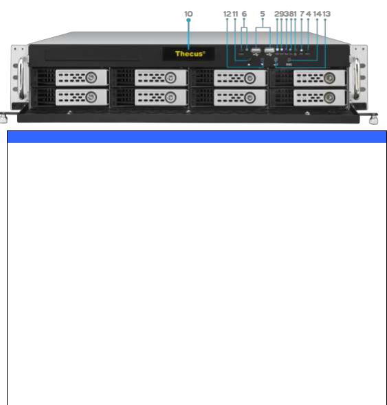
Front Panel
N8900 series:
Front Panel
Item |
Description |
1.Power Button |
Power on/off N8900 |
2.Power LED |
Solid green: System is power on. |
3.System error LED |
Solid RED: System error. |
4.Mute button |
Mute the system fan alarm. |
5.USB Port |
USB 2.0 port for compatible USB devices, such as USB disks and |
|
USB printers |
6. Locator button / |
Press the button, the back led will light up to identify the system |
LED |
position of the rack |
7. RST |
Reboot system. |
8. LAN |
Blinking green: network activity |
|
Solid green: network link |
9. BUSY |
Blinking orange: system startup or system maintenance; data |
|
currently inaccessible |
10.OLED |
Displays current system status and messages |
|
OLED screen saver will be enabled after screen is idle for more |
|
than 3 minutes |
|
OLED screen will be turn off after idle for more than 6 minutes |
11.Up Button ▲ |
Push to scroll up when using the OLED display |
12.Down Button ▼ |
Push to enter USB copy operation screen |
13.Enter Button |
Push to enter OLED operate password for basic system setting |
14.Escape Button |
Push to leave the current OLED menu |
ESC |
|
10
N12000 series:
The Thecus N12000 series front panel has the device’s controls, indicators, and hard disk trays:
Front Panel
Item |
Description |
1.Power Button |
Power on/off N12000 |
2.Power LED |
Solid green: System is power on. |
3.System error LED |
Solid RED: System error. |
4.Mute button |
Mute the system fan alarm. |
5.USB Port |
USB 2.0 port for compatible USB devices, such as USB disks and |
|
USB printers |
6. Locator button / |
Press the button, the back led will light up to identify the system |
LED |
position of the rack |
7. RST |
Reboot system. |
8. LAN |
Blinking green: network activity |
|
Solid green: network link |
9. BUSY |
Blinking orange: system startup or system maintenance; data |
|
currently inaccessible |
10.OLED |
Displays current system status and messages |
|
OLED screen saver will be enabled after screen is idle for more |
|
than 3 minutes |
|
OLED screen will be turn off after idle for more than 6 minutes |
11.Up Button ▲ |
Push to scroll up when using the OLED display |
12.Down Button ▼ |
Push to enter USB copy operation screen |
13.Enter Button |
Push to enter OLED operate password for basic system setting |
14.Escape Button |
Push to leave the current OLED menu |
ESC |
|
11

N16000 series:
The Thecus N16000 series front panel has the device’s controls, indicators, and hard disk trays:
Front Panel
Item |
Description |
1.Power Button |
Power on/off N16000 |
2.Power LED |
Solid green: System is power on. |
3.System error LED |
Solid RED: System error. |
4.Mute button |
Mute the system fan alarm. |
5.USB Port |
USB 2.0 port for compatible USB devices, such as USB disks and |
|
USB printers |
6. Locator button / |
Press the button, the back led will light up to identify the rack |
LED |
position of the system |
7. RST |
Reboot system. |
8. LAN |
Blinking green: network activity |
|
Solid green: network link |
9. BUSY |
Blinking orange: system startup or system maintenance; data |
|
currently inaccessible |
10.OLED |
Displays current system status and messages |
|
OLED screen saver will be enabled after screen is idle for more |
|
than 3 minutes |
|
OLED screen will be turn off after idle for more than 6 minutes |
11.Up Button ▲ |
Push to scroll up when using the OLED display |
12.Down Button ▼ |
Push to enter USB copy operation screen |
13.Enter Button |
Push to enter OLED operate password for basic system setting |
14.Escape Button |
Push to leave the current OLED menu |
ESC |
|
12

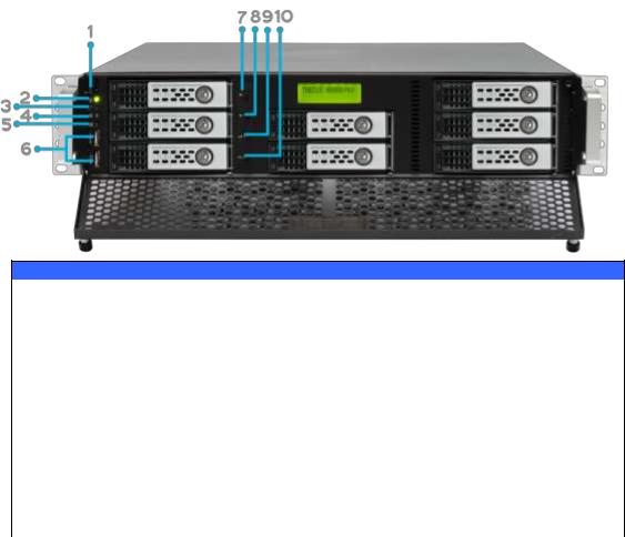
N6850:
The Thecus N6850’s front panel has the device’s controls, indicators, and hard disk trays:
Front Panel
|
Item |
|
Description |
1. |
Power Button |
Power on/off N6850 |
|
2. |
USB Port |
USB 2.0 port for compatible USB devices, such as digital |
|
|
|
|
cameras, USB disks, and USB printers. |
3. |
USB Port |
USB 3.0 port for compatible USB devices, such as digital |
|
|
|
|
cameras, USB disks, and USB printers. |
4. |
LAN2 LED |
Solid white: LAN2 Cable link |
|
|
|
Blinking : Network activity |
|
5. |
LAN1 LED |
Solid white: LAN1 Cable link |
|
|
|
Blinking : Network activity |
|
6. |
USB LED |
Solid white: USB busy |
|
|
|
Solid Red: USB error |
|
7. |
System LED |
Solid white: System is power on. |
|
8. |
OLED |
Displays system status and information |
|
9. |
System Error |
|
Blinking RED: System error. |
|
LED |
|
|
10. |
Down Button |
|
Push to enter USB copy operation screen |
11. |
Up Button |
|
Push to scroll up when using the OLED display |
12. |
Enter Button |
|
Push to enter OLED operate password for basic system |
|
|
|
setting |
13. |
Escape Button |
|
Push to leave the current OLED menu |
13

N8850:
The Thecus N8850’s front panel has the device’s controls, indicators, and hard disk trays:
Front Panel
|
Item |
|
Description |
1. |
Power Button |
Power on/off N8850 |
|
2. |
USB Port |
USB 2.0 port for compatible USB devices, such as digital |
|
|
|
|
cameras, USB disks, and USB printers. |
3. |
USB Port |
USB 3.0 port for compatible USB devices, such as digital |
|
|
|
|
cameras, USB disks, and USB printers. |
4. |
LAN2 LED |
Solid white: LAN2 Cable link |
|
|
|
Blinking : Network activity |
|
5. |
LAN1 LED |
Solid white: LAN1 Cable link |
|
|
|
Blinking : Network activity |
|
6. |
USB LED |
Solid white: USB busy |
|
|
|
Solid Red: USB error |
|
7. |
System LED |
Solid white: System is power on. |
|
8. |
OLED |
Displays system status and information |
|
9. |
System Error |
|
Blinking RED: System error. |
|
LED |
|
|
10. |
Down Button |
|
Push to enter USB copy operation screen |
11. |
Up Button |
|
Push to scroll up when using the OLED display |
12. |
Enter Button |
|
Push to enter OLED operate password for basic system |
|
|
|
setting |
13. |
Escape Button |
|
Push to leave the current OLED menu |
14

N10850:
The Thecus N10850’s front panel has the device’s controls, indicators, and hard disk trays:
Front Panel
|
Item |
|
Description |
1. |
Power Button |
Power on/off N10850 |
|
2. |
USB Port |
USB 2.0 port for compatible USB devices, such as digital |
|
|
|
|
cameras, USB disks, and USB printers. |
3. |
USB Port |
USB 3.0 port for compatible USB devices, such as digital |
|
|
|
|
cameras, USB disks, and USB printers. |
4. |
LAN2 LED |
Solid white: LAN2 Cable link |
|
|
|
Blinking : Network activity |
|
5. |
LAN1 LED |
Solid white: LAN1 Cable link |
|
|
|
Blinking : Network activity |
|
6. |
USB LED |
Solid white: USB busy |
|
|
|
Solid Red: USB error |
|
7. |
System LED |
Solid white: System is power on. |
|
8. |
OLED |
Displays system status and information |
|
9. |
System Error |
|
Blinking RED: System error. |
|
LED |
|
|
10.Down Button |
|
Push to enter USB copy operation screen |
|
11.Up Button |
|
Push to scroll up when using the OLED display |
|
12.Enter Button |
|
Push to enter OLED operate password for basic system |
|
|
|
|
setting |
13.Escape Button |
|
Push to leave the current OLED menu |
|
15

N7700PRO V2/N7710 series/N7770-10G:
The Thecus N7700PRO V2/N7710 series front panel has the device’s controls, indicators, and hard disk trays:
Front Panel
Item |
Description |
1.Power LED |
Solid blue: System is power on. |
2.System LED |
Solid orange: system is being upgraded or system startup; data |
|
currently inaccessible |
3.WAN/LAN1 LED |
Solid green: network link |
|
Blinking green: network activity |
4.LAN2 LED |
Solid green: network link |
|
Blinking green: network activity |
5.USB Copy LED |
Solid blue: files are being copied from a USB storage device |
6.eSATA link LED |
Solid blue: external eSATA device has connected |
(N7700PROv2) |
|
7.USB Port |
USB 2.0 port for compatible USB devices, such as USB disks. |
8.Power Button |
Power on/off N7700PRO V2/N7710 series/N7770-10G |
9.Up Button ▲ |
Push to scroll up when using the LCD display |
10.Down Button ▼ |
Push to enter USB copy operation screen |
11.Enter Button |
Push to enter LCD operate password for basic system setting |
12.Escape Button |
Push to leave the current LCD menu |
ESC |
|
13.LCD Display |
Displays current system status and warning messages |
14.HDD Trays |
Seven 3.5” SATA HDD trays |
|
Locks are provided for added security |
16
N8800PRO V2/N8810U series/N8880U-10G:
The Thecus N8800PRO V2/N8810U series front panel has the device’s controls, indicators, and hard disk trays:
Front Panel
Item |
Description |
1.Power Button |
Power on/off N8800PRO V2/N8810U series/N8880U-10G |
2.Power LED |
Solid green: System is power on. |
3.Reboot Button |
Press to system reboot |
|
|
4.System fan alarm |
Solid red: system fan failure notification |
LED |
|
5. Mute button |
Mute the system fan alarm. |
6.USB Port |
USB 2.0 port for compatible USB devices, such as USB disks, USB |
|
printers |
7.Up Button ▲ |
Push to scroll up when using the LCD display |
8.Down Button ▼ |
Push to enter USB copy operation screen |
9.Enter Button |
Push to enter LCD operate password for basic system setting |
10.Escape Button |
Push to leave the current LCD menu |
ESC |
|
17

N5550:
The Thecus N5550 front panel has the device’s controls, indicators, and hard disk trays:
Front Panel
Item |
Description |
1.System LED |
Blinking orange: System is being upgraded or ;is starting up; |
|
data currently inaccessible |
2.WAN/LAN1 LED |
Solid green: Network link |
|
Blinking green: Network activity |
3.LAN2 LED |
Solid green: Network link |
|
Blinking green: Network activity |
4.USB Copy LED |
Solid blue: Files are being copied from a USB storage device |
5.Syetem Warning LED |
Solid RED: System error |
6.Reset Button |
Resets system configuration to default value. |
7.USB Port |
USB 3.0 port for compatible USB devices, such as USB disks. |
8.Power Button/ Power |
Power on/off N5550 and Power LED. |
LED |
Solid blue: System is power on. |
9.Up Button ▲ |
Push to scroll up when using the LCD display. |
10.Down Button ▼ |
Push to enter the USB copy operation screen. |
11.Enter Button |
Push to enter LCD administrator password to access basic |
|
system setting. |
12.Escape Button ESC |
Push to leave the current LCD menu. |
13.LCD Display |
Displays current system status and warning messages. |
14.HDD Trays |
Five 3.5” SATA HDD trays. |
|
Locks are provided for added security. |
18

N5810/N5810PRO:
The Thecus N5810/N5810PRO front panel has the device’s controls, indicators, and hard disk trays:
Front Panel
Item |
Description |
1. Power LED |
White: System is power on. |
2.WAN/LAN1 LED |
White: Network activity |
3.LAN2 LED |
White: Network activity |
4.USB Copy LED |
White: Files are being copied from a USB storage device |
|
Red: USB copy error |
5. System LED |
White: System is being upgraded or ;is starting up; data |
|
currently inaccessible |
|
RED: System error |
6.USB Port |
USB 3.0 port for compatible USB devices, such as USB disks. |
7.Power Button |
Power on/off N5810/N5810PRO and Power LED. |
8.Up Button ▲ |
Push to scroll up when using the LCD display. |
9.Down Button ▼ |
Push to enter the USB copy operation screen. |
10.Enter Button |
Push to enter LCD administrator password to access basic |
|
system setting. |
11.Escape Button ESC |
Push to leave the current LCD menu. |
12.LCD Display |
Displays current system status and warning messages. |
13.HDD Trays |
Five 3.5” SATA HDD trays. |
|
Locks are provided for added security. |
19

N4510U:
The Thecus N4510U front panel has the device’s controls, indicators, and hard disk trays:
Front Panel
|
Item |
Description |
1. |
LCD Display |
Displays the current system status and warning messages. |
|
|
Displays hostname, WAN/LAN1/LAN2 IP addresses, RAID status, |
|
|
and current time. |
2. |
Up Button ▲ |
Push to scroll up when using the LCD display. |
3. |
Down Button |
Push to scroll down when using the LCD display. |
|
▼ |
|
4.Enter Button |
Push to confirm information entered into the LCD display. |
|
5. |
Escape Button |
Push to leave the current LCD menu. |
|
ESC |
|
6. |
Locator Button |
Turns on the LED backlight. |
7. |
USB Port |
USB 3.0 port for compatible USB devices, such as digital cameras, |
|
|
USB disks, and USB printers. |
8. |
PWR LED |
Solid Blue: System is powered on. |
9. |
Busy LED |
Blinking orange: system startup or system maintenance; data |
|
|
currently inaccessible |
10.Error LED |
Solid Red: System alert: Redundant power or system fan failure |
|
|
|
|
|
|
|
11.LAN LED |
Solid green: network link |
|
|
|
Blinking green: network activity |
12.Power Button |
Power the N4510U on/off. |
|
13.Reset Button |
Resets the N4510U. |
|
14.Mute Button |
Mutes the system fan alarm (Can also be managed through the UI) |
|
15.HDD Trays |
Four 3.5” SATA HDD trays. |
|
|
|
Locks are provided for added security. |
20
N4510U PRO:
The Thecus N4510U PRO front panel has the device’s controls, indicators, and hard disk trays:
Front Panel
|
Item |
Description |
1. |
LCD Display |
Displays the current system status and warning messages. |
|
|
Displays hostname, WAN/LAN1 IP addresses, RAID status, |
|
|
and current time. |
2. |
Up Button ▲ |
Push to scroll up when using the LCD display. |
3. |
Down Button ▼ |
Push to scroll down when using the LCD display. |
4. |
Enter Button |
Push to confirm information entered into the LCD display. |
5. |
Escape Button |
Push to leave the current LCD menu. |
|
ESC |
|
6. |
Locator Button |
Turns on the LED backlight. |
7. |
USB Port |
USB 3.0 port for compatible USB devices, such as digital |
|
|
cameras, USB disks, and USB printers. |
8. |
PWR LED |
Solid Blue: System is powered on. |
9. |
Busy LED |
Blinking orange: system startup or system maintenance; |
|
|
data currently inaccessible |
10. |
Error LED |
Solid Red: System alert: Redundant power or system fan failure |
|
|
|
|
|
|
11. |
LAN LED |
Solid green: network link |
|
|
Blinking green: network activity |
12. |
Power Button |
Power the N4510U PRO on/off. |
13. |
Reset Button |
Resets the N4510U PRO. |
14. |
Mute Button |
Mutes the system fan alarm (Can also be managed through |
|
|
the UI) |
15. |
HDD Trays |
Four 3.5” SATA HDD trays. |
|
|
Locks are provided for added security. |
21

N7510:
The Thecus N7510 front panel has the device’s controls, indicators, and hard disk trays:
Front Panel
Item |
Description |
1.Power LED |
Solid blue: System is power on. |
2.System LED |
Solid orange: system is being upgraded or system startup; data |
|
currently inaccessible |
3.WAN/LAN1 LED |
Solid green: network link |
|
Blinking green: network activity |
4.LAN2 LED |
Solid green: network link |
|
Blinking green: network activity |
5.USB Copy LED |
Solid blue: files are being copied from a USB storage device |
6.eSATA link LED |
Solid blue: external eSATA device has connected |
7.USB Port |
USB 3.0 port for compatible USB devices, such as USB disks. |
8.Power Button |
Power on/off N7510 |
9.Up Button ▲ |
Push to scroll up when using the LCD display |
10.Down Button ▼ |
Push to enter USB copy operation screen |
11.Enter Button |
Push to enter LCD operate password for basic system setting |
12.Escape Button |
Push to leave the current LCD menu |
ESC |
|
13.LCD Display |
Displays current system status and warning messages |
14.HDD Trays |
Seven 3.5” SATA HDD trays |
|
Locks are provided for added security |
22

N12850:
The Thecus N12850 front panel has the device’s controls, indicators, and hard disk trays:
Front Panel
Item |
Description |
1.Power Button |
Power on/off N12850 |
2.Power LED |
Solid green: System is power on. |
3.System error LED |
Solid RED: System error. |
4.Mute button |
Mute the system fan alarm. |
5.USB Port |
USB 2.0 port for compatible USB devices, such as USB disks and |
|
USB printers |
6. Locator button / |
Press the button, the back led will light up to identify the system |
LED |
position of the rack |
7. RST |
Reboot system. |
8. LAN |
Blinking green: network activity |
|
Solid green: network link |
9. BUSY |
Blinking orange: system startup or system maintenance; data |
|
currently inaccessible |
10.LCD |
Displays current system status and messages |
|
LCD screen saver will be enabled after screen is idle for more than |
|
3 minutes |
|
LCD screen will be turn off after idle for more than 6 minutes |
11.Up Button ▲ |
Push to scroll up when using the OLED display |
12.Down Button ▼ |
Push to enter USB copy operation screen |
13.Enter Button |
Push to enter OLED operate password for basic system setting |
14.Escape Button |
Push to leave the current OLED menu |
ESC |
|
23

N16850:
The Thecus N16850 front panel has the device’s controls, indicators, and hard disk trays:
Front Panel
Item |
Description |
1.Power Button |
Power on/off N16850 |
2.Power LED |
Solid green: System is power on. |
3.System error LED |
Solid RED: System error. |
4.Mute button |
Mute the system fan alarm. |
5.USB Port |
USB 2.0 port for compatible USB devices, such as USB disks and |
|
USB printers |
6. Locator button / |
Press the button, the back led will light up to identify the rack |
LED |
position of the system |
7. RST |
Reboot system. |
8. LAN |
Blinking green: network activity |
|
Solid green: network link |
9. BUSY |
Blinking orange: system startup or system maintenance; data |
|
currently inaccessible |
10.LCD |
Displays current system status and messages |
|
LCD screen saver will be enabled after screen is idle for more than |
|
3 minutes |
|
LCD screen will be turn off after idle for more than 6 minutes |
11.Up Button ▲ |
Push to scroll up when using the OLED display |
12.Down Button ▼ |
Push to enter USB copy operation screen |
13.Enter Button |
Push to enter OLED operate password for basic system setting |
14.Escape Button |
Push to leave the current OLED menu |
ESC |
|
24

Rear Panel
N8900
Back Panel
Item |
Description |
1.Power Connector |
Connect the included power cords to these connectors |
2.Serial Port |
This port is for external UPS device |
3.eSATA Port |
eSATA port for high-speed storage expansion |
4.USB Port |
USB 2.0 port for compatible USB devices, such as USB disks, and |
|
USB printers |
5.USB Port |
USB 3.0 port for compatible USB devices. |
6.WAN/LAN1 Port |
WAN/LAN1 port for connecting to an Ethernet network through a |
|
switch or router |
7.LAN2 Port |
LAN2 port for connecting to an Ethernet network through a switch |
|
or router |
8.LAN3 Port |
LAN3 port for connecting to an Ethernet network through a switch |
|
or router. |
N12000:
The N12000 rear panel features ports and connectors.
Back Panel
Item |
Description |
1.Power Connector |
Connect the included power cords to these connectors |
2.Serial Port |
This port is for external UPS device |
3.eSATA Port |
eSATA port for high-speed storage expansion |
4.USB Port |
USB 2.0 port for compatible USB devices, such as USB disks, and |
|
USB printers |
25
5.USB Port |
USB 3.0 port for compatible USB devices. |
6.WAN/LAN1 Port |
WAN/LAN1 port for connecting to an Ethernet network through a |
|
switch or router |
7.LAN2 Port |
LAN2 port for connecting to an Ethernet network through a switch |
|
or router |
8.LAN3 Port |
LAN3 port for HA connecting. |
N12000V/N12000PRO:
N12000V/N12000PRO rear panel features ports and connectors.
Back Panel
Item |
Description |
1.Power Connector |
Connect the included power cords to these connectors |
2.Serial Port |
This port is for external UPS device |
3.eSATA Port |
eSATA port for high-speed storage expansion |
4.USB Port |
USB 2.0 port for compatible USB devices, such as USB disks, and |
|
USB printers |
5.USB Port |
USB 3.0 port for compatible USB devices. |
6.WAN/LAN1 Port |
WAN/LAN1 port for connecting to an Ethernet network through a |
|
switch or router |
7.LAN2 Port |
LAN2 port for connecting to an Ethernet network through a switch |
|
or router |
8.LAN3 Port |
LAN3 port for HA connecting. |
9.HDMI Port |
For Video/Audio out |
10. Mic input |
Microphone input |
11. Line out |
For Audio out |
12.Line in |
For Audio in |
26

N16000:
The N16000 rear panel features ports and connectors.
Back Panel
Item |
Description |
1.Power Connector |
Connect the included power cords to these connectors |
2.Serial Port |
This port is for external UPS device |
3.eSATA Port |
eSATA port for high-speed storage expansion |
4.USB Port |
USB 2.0 port for compatible USB devices, such as USB disks, and |
|
USB printers |
5.USB Port |
USB 3.0 port for compatible USB devices. |
6.WAN/LAN1 Port |
WAN/LAN1 port for connecting to an Ethernet network through a |
|
switch or router |
7.LAN2 Port |
LAN2 port for connecting to an Ethernet network through a switch |
|
or router |
8.LAN3 Port |
LAN3 port for HA connecting. |
27

N16000V/N16000PRO:
N16000V/N16000PRO rear panel features ports and connectors.
Back Panel
Item |
Description |
1.Power Connector |
Connect the included power cords to these connectors |
2.Serial Port |
This port is for external UPS device |
3.eSATA Port |
eSATA port for high-speed storage expansion |
4.USB Port |
USB 2.0 port for compatible USB devices, such as USB disks, and |
|
USB printers |
5.USB Port |
USB 3.0 port for compatible USB devices. |
6.WAN/LAN1 Port |
WAN/LAN1 port for connecting to an Ethernet network through a |
|
switch or router |
7.LAN2 Port |
LAN2 port for connecting to an Ethernet network through a switch |
|
or router |
8.LAN3 Port |
LAN3 port for HA connecting. |
9.HDMI Port |
For Video/Audio out |
10.Line in |
For Audio in |
11. Line out |
For Audio out |
12. Mic input |
Microphone input |
28

N12850/N16850:
N12850/N16850 rear panel features ports and connectors.
Back Panel
Item |
Description |
1.Power Connector |
Connect the included power cords to these connectors |
2. PS/2 connector |
The color-coded PS/2 connection ports (purple for keyboard and |
|
green for mouse) |
3.USB Port |
USB 2.0 port for compatible USB devices, such as USB disks, and |
|
USB printers |
4.Serial Port |
This port is for external UPS device |
5.VGA Port |
For Video out |
6.USB Port |
USB 3.0 port for compatible USB devices. |
7. LAN1\LAN2\ |
LAN1\LAN2\ LAN3\ LAN4 port for connecting to an Ethernet |
LAN3\ LAN4 Port |
network through a switch or router |
8. SFF-8644 SAS |
Support Capacity expansion via Thecus JBOD device |
Wide Port |
|
29

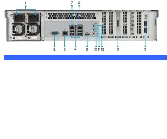
N6850:
The N6850 rear panel features ports and connectors.
Back Panel
Item |
Description |
1.Power Connector |
Connect the included power cords to these connectors |
2.Serial Port |
This port is for external UPS device |
3.eSATA Port |
eSATA port for high-speed storage expansion |
4.USB Port |
USB 2.0 port for compatible USB devices, such as USB disks, and |
|
USB printers |
5.USB Port |
USB 3.0 port for compatible USB devices. |
6.WAN/LAN1 Port |
WAN/LAN1 port for connecting to an Ethernet network through a |
|
switch or router |
7.LAN2 Port |
LAN2 port for connecting to an Ethernet network through a switch |
|
or router |
8.HDMI Port |
For Video/Audio out |
9.Line in |
For Audio in |
10. Line out |
For Audio out |
11. Mic input |
Microphone input |
12. User GPIO |
Could define each GPIO (0~7) and implement its own |
|
functionality. |
|
|
30
Loading...