


Digi 322
365-Day One, Two and Four Circuit Electronic Time Switch by Grasslin
Operating Instructions
The Digi 322 controls are one, two and four channel electronic time switches with 365day, 7-day and 24-hour programming. The channels are freely programmable with a total of 322 schedules. The load status, time of day, and date are displayed on a large LCD readout.
TECHNICAL DATA |
|
Input Voltage: |
Separate models available for |
|
24V, 120V or 240VAC, 50-60 Hz input |
Relay Switch Rating: |
16A @ 24/250 VAC |
Output Relay: |
SPDT dry contacts for each channel |
Power Consumption |
5 VA |
Battery Backup: |
150 hours minimum, |
|
rechargeable battery is built in |
Temperature Range: |
14°F – 131°F (–10°C to 55°C) |
Display: |
AM/PM LCD 7/8" x 1-5/8" |
Dimensions: |
H 3-1/4" x W 4-1/8" x D 2-7/8" |
Weight: |
18 oz. |
Mounting: |
Surface & DIN rail (NEMA 1 indoor & |
|
NEMA 3R outdoor enclosures available) |
Shortest Switching Time: One second |
|
Block Programming: |
Weekdays |
Functional Description
The Digi 322 time control can be programmed as 24-hour, 7-day, or a 365-day schedule of individual holidays or holiday/vacation periods. This control incorporates a calendar through the year 2090 and also includes automatic leap year adjustment. The annual daylight savings/standard time changes can be programmed to occur automatically each year through 2090.
Holidays that occur on the same date each year (July 4) need only be programmed once—they will be stored and will be executed each year until 2090. Holidays that occur on a different date each year (Labor Day) should be entered with the 1X key (one-time). They will be automatically neutralized after their occurrence, therefore, they need not be deleted when programming the control next year. These features minimize the annual programming considerably.
Please read these operating instructions carefully so that you will be able to take full advantage of the functions offered by the Digi 322 time control.
TO THE INSTALLER:
1.Read operating instructions carefully.
2.Check the input voltage ratings marked on the unit to make sure this product is suitable for your power supply and application.
3.Disconnect power supply prior to installation to prevent electrical shock.
4.Damage to the relay-contacts caused by short circuiting will void warranty.
5.Wire in accordance with National and Local electrical code requirements.

Installation
MOUNTING
Surface mounting the Digi 322 inside a control panel or enclosure is accomplished with the supplied rail— the rail is surface mounted with two screws. Mount at convenient eye level position.
Dimensions
You are now ready to affix the unit to the rail. Place the two protruding guides, which are on the top of the rear rail cutout slot, over the top lip of the rail; then snap the bottom into place.
The timer module can be removed from the timer housing for programming or change-out purposes.
Please note that the battery needs to be charged beforehand.
NOTE: After applying power, it may take a few minutes for the battery to charge and display to appear.
WIRING
Make certain to connect only to the supply voltage designated on the unit itself. Warranty will be void if wrong voltage is applied. Connect wires to the screw terminals in accordance with the wiring diagram shown (use 12 to 22 AWG wire).
Terminal Connections
Digi 322-45/4Y |
|
||
CH 1 |
CH 2 |
CH 3 |
CH 4 |
M |
|
|
|
~ |
|
|
|
1 |
2 |
3 |
4 |
5 |
6 |
7 |
8 |
9 |
10 |
11 |
12 |
13 |
14 |
15 |
* |
|
|
NO |
|
NC NO |
|
NC NO |
|
NC NO |
|
NC |
|||
*No internal connection. May be used as ground wire tie point.
Digi 322-45/2Y |
Digi 322-45/1Y |
CH 1 |
CH 2 |
CH 1 |
M |
|
M |
~ |
|
~ |
1 |
2 |
3 |
4 |
5 |
6 |
7 |
8 |
9 |
1 |
2 |
3 |
4 |
5 |
6 |
* |
|
|
NO |
|
NC NO |
|
NC |
* |
|
|
NO |
|
NC |
|
*No internal connection. May be used as ground wire tie point.
Install both terminal covers after wiring. Depending on installation you may want to wire unit before snapping to rail. For stand-alone installation use a Grasslin indoor/outdoor enclosure, E100, E150, or E200.
INSTALLATION CHECKLIST
1.The time switch should have its own independent circuit for power supply.
2.Since all electronic instruments are sensitive to voltage spikes, close attention must be paid to the following:
a)If possible, power to the electronic time switch should be supplied from a phase different from the one supplying power to the load.
b)INDUCTIVE-LOADS should have suitable
VARISTOR and RC network (  ) across the supply terminals to reduce voltage spikes.
c)DC INDUCTIVE LOADS should have a diode across their terminals to eliminate back EMF of the inductor.
d)HIGHLY INDUCTIVE LOADS, especially fluorescent lights, may require a relay in which case (a) and (c) apply.
e)IN HIGH LIGHTNING AREAS, a surge suppressor should be installed.
2
KEYPAD DESCRIPTION
Mo – Su |
– Day selector |
Reset* |
– Clears all programs and actual time |
S/W* |
– Switch for daylight savings time functions |
Prior. |
– Sets priorities |
Year |
– Sets year when setting actual time or DST |
CL |
– To cancel an individual program step |
R |
– Used to review the program |
1X |
– Used to enter a one time schedule |
N– Used to enter an intermediate step in a program block
– Recalls actual time (Time of Day)
S– Used to store the final step in a program block
|
|
|
|
|
– Sets the momentary contact |
|
|
|
|
|
|
|
|
|
|
|
– Used to set the end of a multiday |
|
|
|
|
|
holiday period |
Day |
– Used to set the day of the month |
||||
Month |
– Used to set the month |
||||
|
h+ |
– Hour advance |
|||
|
|
h– |
– Hour reverse |
||
|
m+ |
– Minute advance |
|||
|
m– |
– Minute reverse |
|||
|
I/O |
– Sets ON (1), OFF (0) command for each |
|||
|
|
|
|
|
channel |
 – Manual override for each channel *Recessed buttons—use a long pen point or pencil
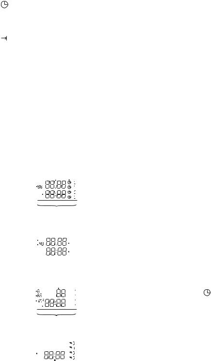
LCD DISPLAY ELEMENTS
The LCD incorporates a number of different elements to display various data and information.
1. Example: Actual date and time of day
|
|
|
|
Date |
Automatic Mode Symbol |
|||
Year |
|
|
|
|
|
|
|
Channel Indicator |
|
|
|
|
|
|
|
||
|
|
|
|
|
|
|
in Automatic Mode |
|
|
|
|
|
|
|
|
|
|
Time of Day |
|
|
|
|
|
|
}(All 4 OFF) |
|
|
|
|
|
|
|
|||
Weekdays
2. Example: Daylight savings time
Daylight Savings Symbol |
|
+1h |
|
Beginning Date |
|
|
|
||||
AUTOMATIC |
|
|
|
|
Ending Date |
|
|
|
|
|
|
|
|
|
|
|
|
|
|
|
|
|
|
3. Example: Momentary Contact
|
|
|
|
|
Duration (Seconds) |
|
|
||||
Priority |
|
|
|
|
|
|
|
|
} |
Channel Selection 1...4 |
|
|
|
|
|
|
|
|
|
||||
|
|
|
|
|
|
|
|
||||
Block |
|
|
|
|
|
|
|
|
|||
|
|
|
|
|
|
|
|
||||
Momentary Contact Symbol |
|
|
|
|
|
|
|
|
(Only ON Commands) |
||
|
|
|
|
|
|
|
|
||||
Switching Time |
|
|
|
|
|
|
|
|
|||
|
|
|
|
|
|
|
|
||||
|
|
|
|
|
|
|
|
|
|
|
|
|
|
|
|
|
|
Weekdays |
|
|
|||
4. Example: Other displays |
|
|
|||||||||
|
|
|
|
|
|
|
|
|
|
} |
|
|
|
|
|
|
|
|
|
|
FIX |
Manual Override |
|
|
|
|
|
|
|
|
|
|
FIX |
||
|
|
|
|
|
|
|
|
|
Indicators (OFF) |
||
One Time Symbol |
|
|
|
1x |
|
|
|
|
FIX |
||
|
|
|
|
|
Temporary and Fixed |
||||||
|
|
|
|
|
|
|
|
|
FIX |
||
|
|
|
|
|
|
|
|
|
|
||
|
|
|
|
|
|
|
|
|
|
|
|
|
|
|
|
|
|
|
|
|
|
|
|
Switching Time
PROGRAM BLOCK FORMATION
The purpose of the blocks is to simplify the programming, i.e. switching times that are the same for different holidays or periods need not be repeated. Likewise, when programming ON and OFF times the date need only be entered once.
The time switch assigns a block number from 00 to 99 to each program with dates entered. All programs without a date (7-day programs) automatically receive the block number 00.
Programs with dates – individual days or periods of days – are assigned an ascending block number (01, 02...99). All programs within a block are stored by pressing “N”. The last program or portion of a program within a block is entered by pressing “S”, thus closing the block.
Execution of Programs
At beginning of each day the microprocessor determines which of the stored programs for that day have the highest priority. Only the highest priority program(s) will be executed.
Once the Digi 322 is programmed, it will automatically “look back” and assume the correct ON or OFF switch position.
PRIORITY
The microprocessor automatically assigns the lowest priority – “0” – to standard 7-day programs.
Holiday programs with a duration of more than one day automatically receive priority “1”.
Holiday programs for one day only automatically receive priority “2”.
A higher priority can be manually assigned to any holiday program by using the “Prior.” key.
PROGRAM STORAGE CAPACITY
The Digi 322 can store up to 322 programs. These 322 programs can be freely assigned to different dates or periods, switching times or channels. A storage position is used each time the button “N” or “S” is pressed. If all 322 storage positions are used up, four 8’s will be shown in the display.
If a program step is not complete and storage is attempted with the “N” or “S” button, the missing components will blink in the LCD.
SETTING THE TIME
[Example: 8:15 AM, July 10, 1996]
Press “Reset” to clear the time and all programs.
While holding : |
|
Press “Year” |
to 96 |
Press “Month” |
to 7 (July) |
Press “Day” |
to 10 |
Press “h+” |
to 8 (AM) |
Press “m+” |
to 15 |
Release the  . The current date and time will be displayed, as will the day of the week; the time colon will blink. Channel settings and override status will be indicated on the right and the +1h indicates that Daylight Savings Time is in effect, if appropriate.
3
 Loading...