


1. |
Contents |
|
2 |
|
|
|
|
1. |
Contents |
Page |
|
2. |
Safety instructions |
3 |
|
3. |
Assembly, putting into operation, connection |
4 |
|
4. |
Control elements |
5 |
|
5. |
Display |
6 |
|
6. |
General |
7 |
|
7. |
Factory setting |
8 |
|
7.1 |
Changing the settings |
10 |
|
7.2 |
Selecting the operating mode |
11 |
|
7.2.1 AU |
= Automatic switchover |
11 |
|
7.2.2 cHA = Weekday-related switchover |
12 |
||
7.2.3 no |
= No switchover |
13 |
|
8. |
Switching commands |
14 |
|
9. |
Date |
|
16 |
9.1 |
Single date without/with year |
17 |
|
9.2 |
Date range without/with year |
18 |
|
10. |
Priority |
20 |
|
11. |
Pulse switching commands |
21 |
|
12. |
Cycle switching commands |
23 |
|
13. |
Read – Change – Delete – Reset |
26 |
|
14. |
Manual switch |
30 |
|
15. |
DCF77 radio mode |
30 |
|
16. |
Technical data |
31 |
|

2. |
Safety information |
|
3 |
|
|
|
|
Installation must be carried out and inspected by a specialist or under his supervision.
For assembly:
•Suitable for use in ambient conditions with normal contamination levels
•Use the appropriate Grässlin accessories for wall surface-mounting.
If correctly installed in accordance with VDE 0100, Part 40, the parts with which contact is still possible can be regarded as double-insulated (protection class II).
For operation:
•We place high demands on the EMC interference resistance of the electronics when developing our products. The interference immunity achieved significantly exceeds the currently valid requirements of the appropriate EN standards.
•In individual cases, check whether additional protection measures are still necessary, e.g. the installation of appropriate components (varistor, suppresser diode, RC element).
•In extreme cases, it is recommended to install another module, e.g. isolating relay or switching contacter, mains interference suppresser filter.
For operation:
•No metallic pointed objects (e.g. needles) may be used on keys pressed with a tool.
Important:
•Only safety extra-low voltage may be connected for operating the clock with safety extra-low voltage.
•When operating the clock with function extra-low voltage, either the mains voltage (230 V AC) or function extra-low voltage may be connected. In these cases, it is not permissible to connect safety extra-low voltage.
GB
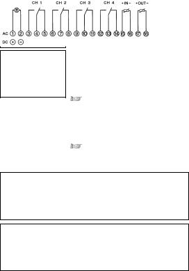
3. |
Assembly, putting into operation, connection |
|
4 |
|
|
|
|
Note:
The time switch is automatically active after approx. 1–2 minutes
3.1Assembly
Fit the time switch
•on a DIN rail
•Wall surface-mounting is optional Surface-mounting set for 6 modular spacings Article No. 03.59.0046.2
3.2Putting into operation
The time and date have been set at the factory.
The time switch is in power-save mode.
Only the colon flashes.
Press any key:
•The time switch is active
•It shows the time (day of the week)
3.3Connection
See information on the unit. Press any key:
•The time switch is active
•It shows the date, time and day of the week
4. |
Control elements |
|
5 |
|
|
|
|
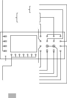
Hand switch
|
Select minutes/seconds |
|
|
for cycle/pulse functions |
|
|
set |
Minutes |
|
Hours |
|
|
|
|
|
|
Years |
set |
Calendar month |
|
|
Calendar day |
|
|
up to, for date range |
|
Summer time/winter time switchover |
||
|
Reset |
|
Select pulse |
|
|
|
|
||
|
|
|
Select cycle |
|
|
|
Current date, time settings |
||
|
|
Begin program input |
||
|
|
Send/receive IR |
||
Select days of the week |
Priority |
|||
Delete |
||||
1 |
= Monday |
|
||
|
|
|||
2 |
= Tuesday |
|
|
|
3 |
= … |
|
|
|
GB

5.Display
Day (US month)
Pulse (minutes)
Cycle (minutes)
Channel 1
Continuous operation
Manual operation
Automatic operation
Switching state
Channel 2
Channel 3
Channel 4
1234567 = Day of the week
Hours
Year number
Minute
6
Month (US day)
Pulse (seconds)
Cycle (seconds)
Year number
Block number
Priority
Summer time/ winter time switchover
Automatic operation
DCF 77
Radio reception
Pulse
Cycle
12 h/24 h display

6. General |
|
7 |
|
|
|
6.1Block numbers
Block numbers are automatically issued during programming. There are block numbers from 00 ....... 99 (note block principle).
All switching commands without date assignment always receive the block number 00. (Priority 0 is always assigned to the block number 00 – it cannot be changed).
All switching commands with date assignment receive the block numbers from 01 ..... 99.
These are issued in ascending order.
6.2Priority
Switching commands with a date assignment can be occupied with different priorities.
If you start with a date when entering the program, a new block number and priority 2 are always offered.
The priority can be changed between 1 and 9, (see Section 10).
The switching command with a higher priority is executed first.
6.3Saving the switching program
In the current operating state (colon flashing), the time switch offers the possibility of using the entered switching program with the function:
•Back Up – can be saved in “background“
•Restore – restores to the foreground
•Change – 2 switching program alternately
GB
6. General |
|
8 |
|
|
|
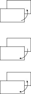
Program saved
current program
Program saved
current program
Program saved
current program
Back Up
with the key Prog and 1 (Day key)
The switching program in the foreground is preserved and can be changed as required.
If necessary, call up the original switching program again with the Restore function.
Restore
with the key Prog and 7 (Day key)
The switching program in the
foreground can be changed as required. The saved and the current switching programs can be used alternately
with the Change function.
Change
with the key Prog and 4 (Day key)
Both switching programs can be used, changed and saved independently
of each other.
6. General |
|
9 |
|
|
|
6.4Programming at the desk
The control section can be removed and programming can be conveniently performed at the desk.
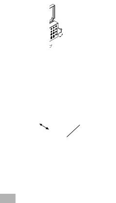
6.5Programming with the talento taxxi (manual programming unit)
The talento taxxi offers the most convenient method for transferring the switching programs.
6.5.1From time switch to time switch (from control section to control section – without mains voltage!). The switching programs are read out from one time switch and are transferred to
the next one – see the talento taxxi operating instructions.
|
talento taxxi |
Note: |
If the data is not correctly transferred, the error |
|
message Er 02 appears in the display of the |
|
time switch. |
•Check the time switch type
A switching program can only be transferred to a time switch of the same type.
•Transfer the program again. There may be a read/wire error.
GB

6. General |
|
10 |
|
|
|
6.5.2Compile your switching programs on a PC with the software talento dialog. They are then transferred to the taxxi via the PC interface.
With the taxxi, the switching programs are now transferred to the relevant time switch (control section) via the infrared interface. Refer to the talento dialog manual.
Note: |
Software and accessories can be ordered separately: |
|
|
• talento taxxi set |
Art.No.: 07.01.0029.1 |
|
consisting of: |
|
•Software talento dialog, including manual
•talento taxxi (manual programming unit)
•Cable 1:1 for the serial interface
• talento taxxi |
Art.No.: 07.01.0030.1 |

6. General |
|
11 |
|
|
|
6.6Service
6.6.1Error messages
The time switch signals malfunctions:
•Er 04 – in the event of incorrect access to
the EEProm. This error message can appear in individual cases. Press any key and the time switch will continue to run normally.
If this error message appears often, we recommend that the time switch be replaced.
Consult your dealer.
•Er 02 – in the event of incorrect transfer via the IR interface.
Transfer the program again. There may be read/write errors.
•Er 01 – If the battery voltage is too low.
6.6.2Lithium battery (service life, type: see Technical data)
If the battery voltage falls to below a value which does not guarantee functioning of the time switch (error message Er 01) , replace the battery.
Order the battery from your dealer with the article number 09.02.0007.8.
Replacing the battery:
•Remove the control section, see 6.4
•Remove the battery casing
•Carefully remove the connector
•Insert a new battery
•Carefully insert the connector
•Replace the battery casing
GB
7. Factory setting |
|
12 |
|
|
|
The default values correspond to Central European Time (CET).
The time switch offers 3 operating modes. The date and time and the operating mode AU are set.
Operating modes:
• AU |
Automatic switchover |
|
of the summer time control function, see Section 7.2.1 |
|
The switchover takes place on the legally defined date. |
• cHA |
Weekday-related switchover |
|
of the summer time control function, see Section 7.2.2 |
|
You enter the summer time end date valid for your location/ |
|
country. |
|
e. g. the first Sunday in April of the current year |
|
(start of summer time) |
|
the last Sunday in October of the current year |
|
(the end of summer time) |
|
In subsequent years, switchover always takes place on the |
|
right day of the week in the correct calendar week. |
• no |
No switchover, see Section 7.2.3 |
12h/24h switchover (AM/PM)
The time switch is in the current operating state!
Press the key 1x.
The colon does not flash!
Press the 1-key (day of the week) 1x.
AM or PM appears in the display.
Press the  key 1x.
The input is complete.
 Loading...