

Page 1
2.
4
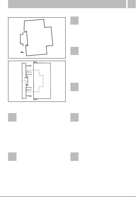
Gerät montieren
• auf DIN-Schiene
• Optionen Wandaufbau
Aufbauset für 2 und 3 TE
Art.Nr. 03.53.0083.2
D
Fit the time switch
• on a DIN rail
• optional wall surface-mounting
Surface mounting set for
3 module spacings
Article No. 03.53.0083.2
GB
Monter l’horloge
• sur rail DIN
• option murale:
set de montage 3 modules
article no. 03.53.0083.2
F
Montate l’interrutore orario
• su barra DIN
• su parete (opzionale)
Set per montaggio a
parete per 3 TE
art. 03.53.0083.2
I
El aparato puede montarse
• Sobre carril
• Fijación opcional a pared
Accesorio de montaje
para 3 módulos
Código 03.53.0083.2
E
Schakelklok monteren
• op DIN-rail
• optie wandopbouw
opbouwset voor 3 TE
Art. nr. 03.53.0083.2
NL
Montáž
• na DIN-lištu
• volitelně na povrch,
na stěnu
objednací číslo pro 3 šířkové
moduly 03.53.0083.2
CZ
Page 2
6
2.
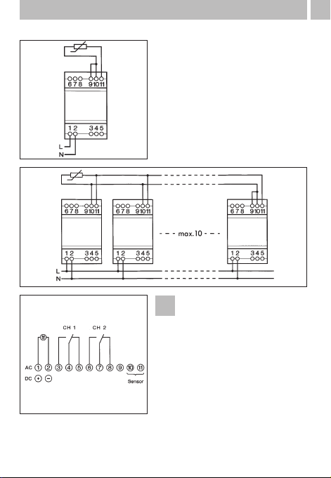
Hinweis:
Beim Anschluss des Sensors an
die Klemmen 10 und 11,
müssen Sie auch zwischen den
Klemmen 9 und 10 eine Brücke
machen.
Wenn Sie mehrere Geräte mit
einem Sensor betreiben, darf
diese Brücke nur an einem
Gerät gemacht werden.
Siehe Anschlussbilder
D
Page 3

2.
7
Note:
When connecting the sensor
to terminals 10 and 11, you
must also insert a jumper between terminals 9 and 10.
When you operate several
units with one sensor, this
jumper may only be inserted
on one unit.
See circuit diagrams.
GB
Attention!
Lors du raccordement du capteur aux bornes 10 et 11, il est
nécessaire aussi d’établir un
pont entre les bornes 9 et 10.
Si plusieurs appareils fonctionnent avec un capteur, ce
pont ne peut être établi que sur
un appareil.
Voir schémas de raccordement.
F
Importante:
Cuando se conecte el sensor
entre los terminales 10 y 11,
debe hacerse siempre un puente entre los terminales 9 y 10.
Cuando se trabaja con varios
aparatos con un único sensor,
este puente sólo es necesario
hacerlo en una unidad.
Ver esquema adjunto.
E
Upozornění:
Při připojení senzoru na svorky
10 a 11, musí být vytvořeno
přemostění také mezi svorkami
9 a 10.
Pokud bude provozováno více
přístroju na jeden senzor, musí
být titi přemostění uděkáno
pouze na jednom přístroji.
Viz schéma zapojení.
CZ
Attenzione:
Con il collegamento del
sensore ai morsetti 10 e 11
dovete fare un ponte anche
tra i morsetti 9 e 10.
Se fate funzionare più apparecchi con un sensore, questo
ponte deve essere fatto solo
su di un apparecchio.
Vedi schemi di collegament.
I
Aanwijzing:
Bij het aansluiten van de
sensor aan de klemmen 10 en
11, moet u ook tussen klemmen 9 en 10 een brug maken.
Wanneer u meerdere apparaten met één sensor aanstuurt,
mag deze brug maar aan één
van deze apparaten gemaakt
worden.
Zie aansluitafbeeldingen.
NL
Page 4

9
3.
Page 5

11
Technical data
GB
45 x 54 x 60
46 x 54
285
see ordering data
approx. 2,5 VA
potential-free
2 changeover contacts
10 A/250 V AC
8 A/250 V AC
2000 W
approx. 800 mA/300 mA/150 mA
electronic
2 lx – 500 lx
approx. factor 1.3 of switch-on value
settable: approx. 0-100 sec. ON/0-100 sec. OFF
without delay
captive +/– screw terminals
yes
–20 °C to +55 °C
–30 °C to +70 °C
II in accordance with EN 60 669-1 and Parts
II in accordance with EN 60 669-1 and Parts
IP 20
IP 65
potential-free
max. 100 m
min. 0,75 mm
2
Dimensions (H x W x D) mm
Distributor cut-out mm
Weight g (approx.)
Connection
Power consumption
at 230 V~ (AC)
Switching output
Switching contacts
Switching capacity AC
– ohmic load (VDE, IEC)
– inductive load cos ϕ 0,6
– glow lamp load
Switching capacity DC
24 V–/60 V–/220 V–
Method of operation,
dimmer switch:
– Adjustment range
– Hysteresis
– Switching delay
– Switching state display
Connection type
Can be lead-sealed
Ambient temperature:
– Control unit
– Brightness sensor
Protection class:
– Control unit
– Brightness sensor
Protection type:
– Control unit
– Brightness sensor
Brightness sensor
– Long connection cable
– Line cross section
 Loading...