

Page 1

INSTALLATION AND USER INSTRUCTIONS
TOWERCHRON QE1/QE2
80.10.0662.7/07/11/02 - 11/00025
Page 2
Congratulations. You are the proud owner of a new GRÄ SSLIN TOWERCHRON QE. We recommend that you read
the operation instructions carefully so that you can make the best use of all features offered by this product.
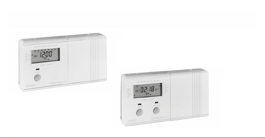
QE1
QE2
Page 3

TECHNICAL DATA
Dimensions 156x85x42 [mm]
Power supply 240V/50Hz
Rating 5A (2A)/240V, per channel
Memory locations 28 per channel
Battery permanently fixed re-chargeable (not replaceable)
Battery reserve 500 hours plus (after 70 hours charge)
Installation double insulated
Fitting surface mounted or single gang plaster depth socket outlet
Maximum ambient temperature 50 °C
Type 1 Action type 1B
Micro disconnection type 1B
Pollution protection normal pollution situation
Page 4
INSTALLATION PROCEDURE
Remove QE1/QE2 from packing and prepare it for use on fully pumped or for gravity hot water systems.
Remove QE1/ QE2 from packing and prepare it for use on fully pumped or for gravity hot water systems.
d.
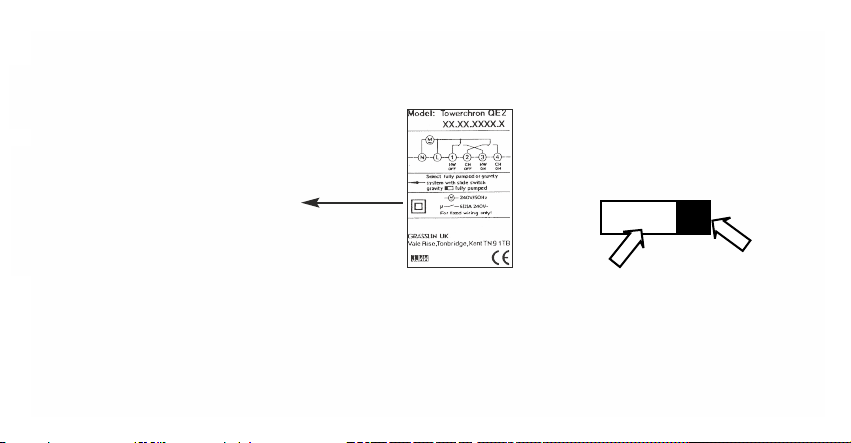
For gravity systems the switch
located at the rear of the QE2
For fully pumped systems the switch
must be moved to the left - into
located at the rear of the “QE2” must
the gravity position
be moved to the right-
into the “fully pumped” position.
For “fully pumped systems” the
switch must be positioned to the
right of the slot.
(when viewed from the rear)
Slot
NB • Installation must be carried out by a qualified electrician and conform to current IEE Regulations.
NB • Mains supply must be suitably fused (usually 3 amps) and provision made for Class A circuit disconnection.
Switch
Page 5

NB • Control is suitable for fixed wiring only.
NB • If the unit is to be surface wired:
- Remove backplate by slackening fixing screw and separate the plate from the timeswitch
- Remove the knock-out from the backplate and the timeswitch
- Screw backplate to wall with counter sunk No. 8. Wood screws, using fixing holes provided.
NB • For socket box mounting:
- Use the centre two holes and fit backplate to box using machine screws
- To ensure clearance for the down flap, ensure that there is a minimum of 4 cm clearance
under the unit when mounted
Page 6

TABLE OF CONTENTS
“TOWERCHRON QE1”
Applications . . . . . . . . . . . . . . . . . . . . . . . . . . . . . . . . . . . . . . . . . . . . . . . . . . . . . . . . . . . 1
Programming your “TOWERCHRON QE1”
Setting current time and day . . . . . . . . . . . . . . . . . . . . . . . . . . . . . . . . . . . . . . . . . . . . . . . . 2
Start the inbuilt standard program . . . . . . . . . . . . . . . . . . . . . . . . . . . . . . . . . . . . . . . . . . . . . 3
View the inbuilt standard program . . . . . . . . . . . . . . . . . . . . . . . . . . . . . . . . . . . . . . . . . . . . . 4
Setting your own time program . . . . . . . . . . . . . . . . . . . . . . . . . . . . . . . . . . . . . . . . . . . . . . . 5-6
View/modify/delete your entered program selections . . . . . . . . . . . . . . . . . . . . . . . . . . . . . . . . 7
Manual override functions (boost, advance, constant, OFF) . . . . . . . . . . . . . . . . . . . . . . . . . . . . 8
General installation instructions . . . . . . . . . . . . . . . . . . . . . . . . . . . . . . . . . . . . . . . . . . . . . . . 9
Internal wiring diagram . . . . . . . . . . . . . . . . . . . . . . . . . . . . . . . . . . . . . . . . . . . . . . . . . . . 10
Wiring installation instructions . . . . . . . . . . . . . . . . . . . . . . . . . . . . . . . . . . . . . . . . . . . . . . . 11 - 15
Page 7

TABLE OF CONTENTS
“TOWERCHRON QE2”
Applications . . . . . . . . . . . . . . . . . . . . . . . . . . . . . . . . . . . . . . . . . . . . . . . . . . . . . . . . . . . 16
Programming your “TOWERCHRON QE2”
Setting current time and day . . . . . . . . . . . . . . . . . . . . . . . . . . . . . . . . . . . . . . . . . . . . . . . . 17
Start the inbuilt standard program . . . . . . . . . . . . . . . . . . . . . . . . . . . . . . . . . . . . . . . . . . . . . 18
View the inbuilt standard program . . . . . . . . . . . . . . . . . . . . . . . . . . . . . . . . . . . . . . . . . . . . . 19, 20
Setting your own heating/hot water program
1. Setting your own heating times . . . . . . . . . . . . . . . . . . . . . . . . . . . . . . . . . . . . . . . . . . . . . 21
Both heating and hot water will be turned ON and OFF at the same time . . . . . . . . . . . . . . . . . . . 22, 23
Heating and hot water will be turned ON and OFF at different times . . . . . . . . . . . . . . . . . . . . . . 24, 25
2. Setting your own hot water times . . . . . . . . . . . . . . . . . . . . . . . . . . . . . . . . . . . . . . . . . . . . 26, 27
View/modify/delete your entered program selections . . . . . . . . . . . . . . . . . . . . . . . . . . . . . . . . 28, 29
Manual override functions (boost, advance, constant, OFF) . . . . . . . . . . . . . . . . . . . . . . . . . . . . . 30, 31
General installation instructions . . . . . . . . . . . . . . . . . . . . . . . . . . . . . . . . . . . . . . . . . . . . . . . 32
Internal wiring diagram . . . . . . . . . . . . . . . . . . . . . . . . . . . . . . . . . . . . . . . . . . . . . . . . . . . . 33
Wiring installation instructions . . . . . . . . . . . . . . . . . . . . . . . . . . . . . . . . . . . . . . . . . . . . . . . . 34- 37
Page 8

Open here, if you are programming Towerchron QE1.
8
Page 9

“ TOWERCHRON QE1”
1
APPLICATIONS (QE1)
• Any simple time switching application up to
the stated rating
• Domestic heating systems where both heating and
hot water services are required to switch ON and
OFF at the same time
• Controlling a “combi“ or “combination boiler“
Page 10
PROGRAMMING YOUR “TOWERCHRON QE1”
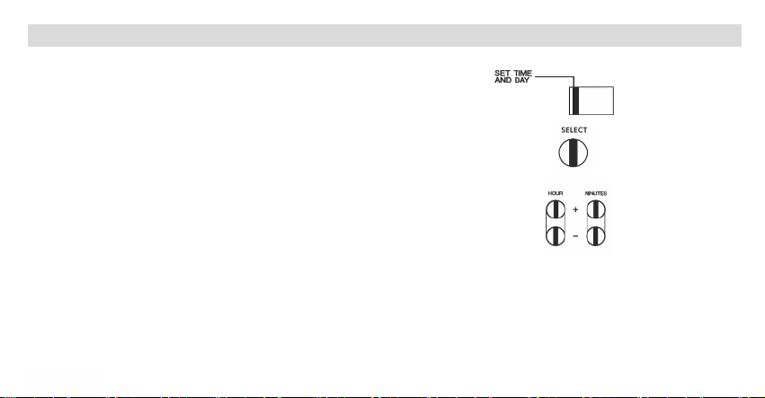
SETTING CURRENT TIME AND DAY
Open the keypad cover
Make sure that the slide switch is on position “SET TIME AND DAY” to left.
If the battery is in a fully discharged condition at the moment of installation
then the screen will be blank. The screen will start to display approximately
2 minutes after plugging into mains supply. Now operate the “RESET” button.
Press the “RESET” button with a dull pointed instrument once
Press the “DAY” button until the actual day is marked
Repeatedly press “HOUR +/-”, then “MINUTES +/-” buttons until
current time is displayed.
NB • If you are setting the clock in wintertime (GMT): The clock is now
correctly set.
If you are setting the clock in summertime (BST): Press
the “SUMMER/WINTER” button once. The arrowhead at the bottom
of the display moves to indicate Summertime, and the clock is
correctly set.
2
Page 11

START THE INBUILT STANDARD PROGRAM
Move the slide switch to position “RUN PRESET PROGRAM”.
NB • The inbuilt standard program is now active.
3
Page 12
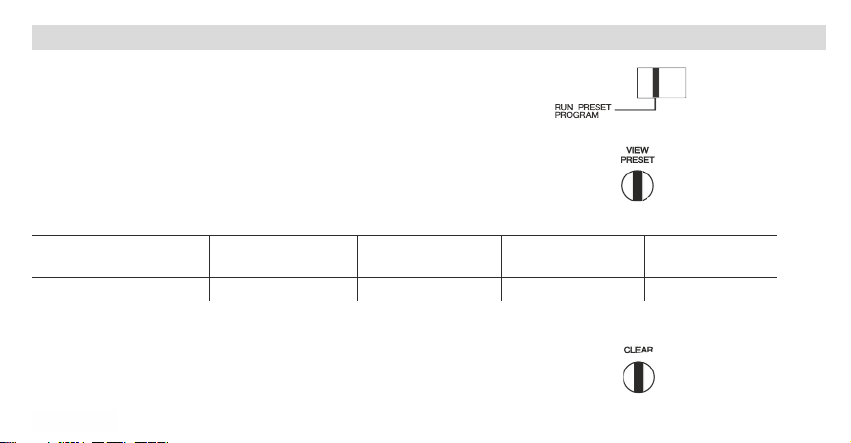
VIEW THE INBUILT STANDARD PROGRAM
Make sure that the slide switch is on position “RUN PRESET PROGRAM”.
Repeatedly press the “VIEW PRESET” button
NB • Each press displays, one step at a time, the ON and OFF times for
heating and hot water. Standard program is shown in the table.
ON OFF ON OFF
Monday to Friday 6.30 a.m. 8.30 a.m. 4.30 p.m. 10.30 p.m.
Saturday to Sunday 8.00 a.m. 11.00 a.m. 4.00 p.m. 11.00 p.m.
To return to time of day
Press the “CLEAR” button
The preset programm is activated
4
Page 13

SETTING YOUR OWN TIME PROGRAM
It is recommended that you write down the switching times.
The following day groups are selectable: Mon...Fri, Sat + Sun, Mon...Sat,
Mon...Sun or any individual day.
Move the slide switch to position “SET OWN PROGRAM”
1. To set “ON” time and day combination:
Press “HOUR +/-” then “MINUTES +/-” buttons
Press “DAY” button to select day/day groups
2. To store “ON” time and view the next program space
Press the “SELECT” button
3. To set the first “OFF” time and day combination
Press “HOUR +/-” then “MINUTES +/-” buttons
(the day/day groups that were selected during “ON” time
programming are still in memory for this “OFF” time)
5
Page 14

4. To store “OFF” time and view the next program space
Press “SELECT” button
Repeat steps 1 to 4 to enter further “ON” and “OFF” times.
28 program spaces are available.
After completing your own program:
Move the slide switch to position “RUN OWN PROGRAM”
NB • The current time is displayed and your own
program is now active.
6
Page 15

VIEW/MODIFY/DELETE YOUR ENTERED PROGRAM SELECTIONS
Move the slide switch to position “ SET OWN PROGRAM”
To view/modify your entered ON/OFF times:
Press the “ SELECT” button repeatedly
NB • While you are viewing any program selection, you can modify the
contents with the “DAY”, “HOUR” and “MINUTES” button.
To delete your entered ON/OFF times:
Press the “ SELECT” button repeatedly until the desired ON or OFF
time to be deleted appears.
Press the “ CLEAR” button. The selection displayed will be deleted.
To return time of day:
Move the slide switch to “ RUN OWN PROGRAM”
7
Page 16

MANUAL OVERRIDE FUNCTIONS
While the timeswitch is in the “RUN PRESET PROGRAM” or “RUN OWN PROGRAM” mode, and without having to
open the keypad cover, you can manually override the program without disrupting the original settings by pressing the
“SELECT” button.
TMD (Timed)
When the “RUN PRESET PROGRAM” or “RUN YOUR OWN PROGRAM” mode is active, the arrow points to TMD
BOOST Press the “SELECT” The timeswitch will
To switch ON button until the arrow in automatically retun to the
for 1 hour the display points to BOOST timed function after 1 hour.
ADV Press the “SELECT” The timeswitch will
To switch ON button until the arrow in automatically go back to the
(or OFF) early the display points to ADV timed function according to the
8
(Advance) next programmed entry.
Page 17

CONST Press the “SELECT” button The timeswitch stays ON permanently
To switch ON until the arrow in the display until you move the arrow by using the
permanently points to CONST (Constant) “SELECT” button again.
OFF Press the “SELECT” button The timeswitch stays OFF permanently
To switch OFF until the arrow in the display until you move the arrow by using
permanently points to OFF the “SELECT” button again.
9
Page 18

INTERNAL WIRING DIAGRAM (QE1)
OFF ON
NB • Carry out wiring installation using appropriate diagram as shown.
NB • When the TOWERCHRON QE1 timeswitch is to be used with a combination boiler, always refer to the boiler
manufacturer instructions concerning wiring before using the information contained in this manual. In some
cases, the boiler manufacturers instructions will contain information regarding removal of certain link wires
and will always indicate the fuse rating for the mains electrical supply.
NB • Plug in unit and secure to the base by tightening fixing screw.
10
Page 19

GENERAL INSTALLATION INSTRUCTIONS (QE1)
Backplate
Fixing
Holes
Terminal
Block
Earth
Terminal
Cable
Knockout
Fixing
Screw
The TOWERCHRON QE1 is double insulated, so earth protection is not required. However, in the backplate a terminal for earth continuity is provided which should be used if earth conductors are present in your cable. Make sure that
the earth conductors are sleeved to prevent accidental contact with live parts.
11
Page 20

WIRING INSTALLATION INSTRUCTIONS (QE1)
Simple circuit for domestic central heating
boiler with gravity hot water supply
This diagram is correct for mains operated systems.
The link wire L-3 must be fitted by the installer.
NB • TOWERCHRON QE1 is ideally suited for controlling combination boilers. The following basic circuit diagrams
apply for range indicated.
12
Room Stat Conversion Chart
E N COM DEM SAT
Tower SS E 4 1 2
Tower RS E 4 1 3
ACL TS 142 E 4 1 2
Drayton RTE E 4 1 2 3
Honeywell T6160B 2 1 3 4
Landis & Gyr RAD5 4 6 2
Switchmaster SRT2 5 1 3 2
Sunvic TLX2259 E 4 3 1
Page 21

IMPORTANT NOTE:
It is important that you always refer to the Boiler Manufacturers Instructions concerning electrical wiring before using
the information contained in this manual. In some cases the Boiler Manufacturers Instructions will contain information
regarding removal of certain link wires and will always indicate the fuse for the main electrical supply.
QE1 Terminals
N
Supply
L
E
Combination boiler model
Chaffoteaux Celtic 2.20 OFF N PH 7 6
ELM Leblanc GVM 420 See special circuit
Glowworm Fuelsaver N L 8 7
Ravenheat N L C D
Saunier Duval SD 620F N L 2 3
Saunier Duval SD 123C N L 2 1
Saunier Duval SD 235C N L 2 1
Saunier Duval SD 135V N L 2 1
Saunier Duval SD 625M See special circuit
13
Roomstat
Page 22

Vaillant VCW 20/1 T3W 1MP 2R 3 4
Vaillant VCW 25/1 T3W 1MP 2R 3 4
Vaillant VCW SINE 18 T3W 1MP 2R 3 4
N L
Vaillant VCW GB 182 EH 1 2 3 4
Vaillant VCW GB 242 EH 1 2 3 4
Vokera 18/72 MCF N L 4 5
Vokera 21/84 MCF N L 4 5
Vokera 21/84 Turbo N L 4 5
Vokera 18/72 DMCF N L 3 4
Vokera 21/84 DMCF N L 3 4
Vokera 21/84 DC Turbo N L 3 4
Vokera 20/80 RS Turbo N L 3 4
Worcester Heatslave Senior 12 N L 2 4
Worcester Heatslave Senior 20430 N L 2 4
Worcester Heatslave Senior 6 N L 2 6
Worcester Heatslave 9-24 RSF N L 1 2
Worcester Heatslave 9-24 BF N L 1 2
Worcester Heatslave 9-24 N L 1 2
Worcester Heatslave High Flow BF N L 2 2
Worcester Heatslave High Flow OF N L 2 3
14
BOILER TERMINAL NUMBERS
Page 23

SAUNIER DUVAL SD625M
Always use the special 24V thermostat supplied with this boiler, and wire as indicated in boiler instructions,
substituting time switch terminals A and B for terminals 3 and 4 respectively on QE1.
Boiler with Timeswitch and Room Thermostat
15
Page 24

ELM Leblanc GVM 420
16
Page 25

Open here, if you are programming Towerchron QE2.
17
Page 26

18
Page 27

“ TOWERCHRON QE2”
19
APPLICATIONS (QE2)
• Fully pumped central heating systems using mid
position valves, spring return valves or
“power open”, power closed valves.
• Gravity hot water, pumped heating systems with
or without motorised valves fitted into the
domestic hot water primary circuit.
Important note:
For gravity systems the switch located at the
For fully pumped systems the switch located at the
rear of the “QE2” must be moved to the right -
rear of the QE2 must be moved to the left -
into the “fully pumped” position.
into the gravity position.
Page 28

PROGRAMMING YOUR “TOWERCHRON QE2”
SETTING CURRENT TIME AND DAY
Open the keypad cover
Make sure that the slide switch is on position
If the battery is in a fully discharged condition at the moment of installation then
the screen will be blank. The screen will start to display 2 minutes after plugging into mains supply. Now operate the “ RESET” button.
Press the “RESET” button with a dull pointed instrument once
Press the “ DAY” button until the actual day is marked
Repeatedly press “HOUR +/-”, then “MINUTES +/-” buttons until
current time is displayed.
NB • If you are setting the clock in wintertime (GMT): The clock is now
correctly set. If you are setting the clock in summertime (BST): Press
the “ Summer/Winter” button once. The arrowhead at the bottom
of the display moves to indicate Summertime, and the clock is
correctly set.
20
“SET TIME AND DAY”
to the left.
Page 29

START THE INBUILT STANDARD PROGRAM
Move the slide switch to position “RUN PRESET PROGRAM”.
NB • The inbuilt standard program is now active.
21
Page 30

VIEW THE INBUILT STANDARD PROGRAM
Make sure that the slide switch is on postion “RUN PRESET PROGRAM”.
Repeatedly press the “COPY” button.
NB • Each press displays, one step at a time, the ON and OFF times for
heating and hot water. Standard program is shown in the table.
HEATING SIDE
22
HOT WATER SIDE
Page 31

ON and OFF times for HEATING and HOT WATER
ON OFF ON OFF
Monday to Friday 6.30 a.m. 8.30 a.m. 4.30 p.m. 10.30 p.m.
Saturday to Sunday 8.00 a.m. 11.00 a.m. 4.00 p.m. 11.00 p.m.
To return to time of day
Press the “CLEAR” button
The preset program is activated.
23
Page 32

SETTING YOUR OWN HEATING/HOT WATER PROGRAM
Both Heating and Hot Water will be turned ON and OFF at the same time.
It is recommended that you write down the switching times (sheet attached).
The following day groups are selectable:
Mon...Fri, Sat + Sun, Mon...Sat, Mon...Sun or any individual day.
Move the slide switch to position “SET OWN PROGRAM”
The first program is displayed.
1. To set “ON” time and day combination:
Press “HOUR +/-” then “MINUTES +/-” buttons
Press “DAY” button to select day/day groups
24
Page 33

2. To copy the first “ON” time for Hot Water:
Press “COPY” button
The arrows on the Hot Water side of the display will flash to confirm the
copy instruction has been carried out.
The display now jumps to the next free program space so that the OFF time can be input. Repeat steps 1 to 2 to
enter further “ON” and “OFF” times.
28 program places are available.
After completing your own program:
Move the slide switch to position “RUN OWN PROGRAM”
NB • The current time is displayed and your own program is
now active.
25
Page 34

SETTING YOUR OWN HEATING/HOT WATER PROGRAM
(Heating and hot water will be turned ON and OFF at different times)
1. Setting your own heating times:
Move the slide switch to position “SET OWN PROGRAM”
The first program space is displayed.
1. To set Heating “ON” time and day combination:
Press the “HOUR +/-” then “MINUTES +/-” buttons
Press the “DAY” button to select day/day groups
2. To store Heating “ON” time and view the next program space
Press the “HEATING” button
26
Page 35

3. To set the first Heating “OFF” time and day combination
Press the “HOUR +/-” then “MINUTES +/-” buttons
(the day/day groups that were selected during “ON” time
programming are still in memory for this “OFF” time)
4. To store Heating “OFF” time and day combination
Press the “HEATING” button
The next free program place is displayed.
Repeat steps 1 to 4 to enter further “ON” and “OFF” times.
After completing your own program:
Move the slide switch to position “RUN OWN PROGRAM”
NB • The current time is displayed and your own progrm
is now active.
27
Page 36

SETTING YOUR OWN HOT WATER TIMES:
Move the slide switch to position “SET OWN PROGRAM”
Press the “HOT WATER” button.
The first program place is displayed.
1. To store Hot Water “ON” time and day combination:
Press the “HOUR +/-” then “MINUTES +/-” buttons
Press the “DAY” button to select day/day groups
2. To store Hot Water “ON” time and view the next program space
Press the “HOT WATER” button
3. To set the first Hot Water “OFF” time and day combination
Press “HOUR +/-” then “MINUTES +/-” buttons
(the day/day groups that were selected during “ON” time
programming are still in memory for this “OFF” time)
28
Page 37

4. To store Hot Water “OFF” time and day combination:
Press the “HOT WATER” button
The next free program place is displayed.
Repeat steps 1 to 4 to enter further “ ON” and “ OFF” times.
After completing your own program:
Move the slide switch to position “RUN OWN PROGRAM”
NB • The current time is displayed and your own program
is now active.
29
Page 38

VIEW/MODIFY/DELETE YOUR ENTERED PROGRAM SELECTIONS
Move the slide switch to position “ SET OWN PROGRAM”
To view/modify your entered program selections:
To view Heating times:
Press the “ HEATING” button repeatedly
To view Hot Water times:
Press the “ HOT WATER” button repeatedly
NB • While you are viewing any program selection, you can modify the
contents with the “DAY”, “HOUR” and “MINUTES” button.
30
Page 39

To delete your entered program selections:
To delete Heating times:
Press the “HEATING” button repeatedly until the desired ON or OFF
time to be deleted appears.
Press the “CLEAR”-button. The selection displayed will be deleted.
To delete Hot Water times:
Press the “HOT WATER” button repeatedly until the desired ON or OFF
time to be deleted appears.
Press the “CLEAR” button. The selection displayed will be deleted.
To return to time of day:
Press the “RUN OWN PROGRAM” button
31
Page 40

MANUAL OVERRIDE FUNCTIONS
With the time switch is in the “ RUN PRESET PROGRAM” or “ RUN OWN PROGRAM” mode, and without having to
open the keypad cover, you can manually override either program without disrupting the original settings by pressing
the “Select” button.
TMD
When the “ RUN PRESET PROGRAM” or “ RUN YOUR OWN PROGRAM” mode is active, the arrow points
to TMD (Timed),
BOOST Press the “ HEATING” or The programmer will
To switch ON “HOT WATER” button until the automatically return to the
for 1 hour arrow in the display points to timed function after 1 hour.
BOOST
ADV Press the “ HEATING” or The programmer will
To switch ON “HOT WATER” button until the automatically go back to the
(or OFF) early arrow in the display points timed function according to
to ADV (Advance) the next programmed entry.
32
Page 41

CONST Press the “HEATING” or The programmer stays ON
To switch ON “HOT WATER” button until the permanently - until you move
permanently arrow in the display points to the arrow by using the “HEATING”
CONST (Constant) or “HOT WATER” button again.
OFF Press the “HEATING” or The programmer stays OFF
To switch OFF “HOT WATER” button until the permanently - until you move
permanently arrow in the display points the arrow by using the “HEATING”
to ADV (Advance) or “HOT WATER” button again.
33
Page 42

34
Page 43

GENERAL INSTALLATIONS INSTRUCTIONS (QE2)
Backplate
Fixing
Holes
Terminal
Block
Earth
Terminal
Cable
Knockout
Fixing
Screw
The TOWERCHRON QE2 is double insulated, so earth protection is not required. However, in the backplate a terminal for earth continuity is provided which should be used if earth conductors are present in your cable. Make sure that
the earth conductors are sleeved to prevent accidental contact with live parts.
35
Page 44

INTERNAL WIRING DIAGRAM (QE2)
NB • Carry out wiring installation using appropriate diagram as shown.
NB • Plug in unit and secure to the base by tightening fixing screw.
Important note:
For fully pumped systems the switch located at the rear of the “QE2” must be moved to the right - into the “fully
pumped” position
36
Page 45

WIRING INSTALLATION INSTRUCTIONS (QE2)
Gravity Hot Water/Pumped Heating - System with roomstat controlled pump
37
Page 46

The following wiring diagrams are schematic only (for clarity the earth and neutral connections are omitted). We suggest when wiring systems, a suitable wiring centre is used (the Tower controls wiring centre is purpose made and
gives full information for wiring this programmer into compatible equipment).
Gravity Hot Water/Pumped Heating System Two Port Valve in D.H.W. with Room and Cylinder Stats
Note: Only valves with “change over” switches are suitable
38
Page 47

Fully Pumped System using 2 Port Spring
Return
39
Fully Pumped System using 3 Port Mid-Position
Valve
Page 48

Conversion Chart for Room / Cylinder Thermostats
Cylinder Stats Room Stats
E C D S
O E A
M M T
Tower CS1
ACL HTS 2
Drayton CS1 E 1 2 3
Honeywell L641 A C 1 2
Landis & Gyr RAM21 1 2 3
Switchmaster SCT1 1 2 3
Sunvic SA 2451 E 3 1 2
40
RED
BLK
YEL
Tower SS E 4 1 2
Tower RS E 4 1 3
ACL TS 142 E 4 1 2
Drayton RTE E 4 1 2 3
Honeywell T 6160B 2 1 3 4
Landis & Gyr RAD5 4 6 2 2
Switchmaster SRT2 5 1 3
Sunvic TLX2259 3 4 3 1
E N C D S
O E A
M M T
 Loading...