

Page 1
Thermostatic mixing valves
INSTALLATION AND OPERATING INSTRUCTIONS
FOR THERMOSTATIC MIXING VALVES COMPLYING WITH
N.H.S ESTATES MODEL ENGINEERING SPECIFICATION D08
THE VALVE COVERED IN THIS BOOKLET HAS BEEN DESIGNED AND MANUFACTURED
TO COMPLY WITH N.H.S ESTATES MODEL ENGINEERING SPECIFICATION D08
IT MAY PERFORM SATISFACTORILY OUTSIDE THE LIMITS SPECIFIED HOWEVER
THIS IS OUTSIDE THE SCOPE OF THE TMV2 AND TMV3 SCHEME
TEMPERATURE STABILISED
THERMOSTATIC MIXING VALVE
INTRODUCTION
It has been recognized that users of hot water in care establishments are at risk from scalding.
This risk has been reduced by the use of thermostatic mixing valves.
In order to assure the performance of thermostatic mixing valves N.H.S. Estates Model
Engineering Specification D08 was created. The valve listed in the following pages has been
designed and manufactured to this standard for use within the Build Cert scheme designated
applications.
This Thermostatic mixing valve has also been designed to the TMV2 scheme which is manufactured
to comply with BS EN 1287(LP) and BS EN 1111(HP)
The following abbreviated designation codes are used throughout this booklet. Detailed descriptions
are given below.
HP High pressure
LP Low pressure
S Shower
B Bidet
W Washbasin
T44 Bath with fill temperature of 44°C max
T46 Bath with fill temperature of 46°C max
BE Bidet with economy flow rate
SE Shower with economy flow rate
WE Washbasin with economy flow rate
DESIGNED FOR USE IN THE FOLLOWING DESIGNATIONS
CODE OPERATING PRESSURE APPLICATION
HP-B HIGH PRESSURE BIDET
HP-S HIGH PRESSURE SHOWER
HP-W HIGH PRESSURE WASH BASIN
LP-B LOW PRESSURE BIDET
LP-S LOW PRESSURE SHOWER
LP-W LOW PRESSURE WASH BASIN
HP-T44 HIGH PRESSURE BATH FILL WITH TEMPERATURE UP TO 44°C
TFC GROUP LLP Tower House, Vale Rise, Tonbridge, Kent TN9 1TB
Tel: 01732 351680 Email: sales@tfc.uk.com Web: www.tfc-group.co.uk
Page 2
Thermostatic mixing valves
NOTE: ALL INSTALLATION AND MAINTENANCE PROCEDURES SHOULD
BE CARRIED OUT IN ACCORDANCE WITH THESE GUIDELINES.
PLEASE READ THESE GUIDELINES BEFORE COMMENCING ANY
NEW INSTALLATION OR SERVICING OF EXISTING UNITS.
INSTALLATION RECOMMENDATIONS
The following general recommendations should be observed.
1) Always install isolating valves to facilitate servicing.
2) Always flush both supply pipes fully before connecting mixing valve to ensure no pipe debris
enters the inlets. Always fit filters provided.
3) All installations must comply with current local water company regulations.
TO CLEAN
1. Soak all metal parts in de-scaler, wash off in clean water.
2. Lightly grease all metal parts with silicone grease.
3. Replace worn and damaged ‘O’ rings.
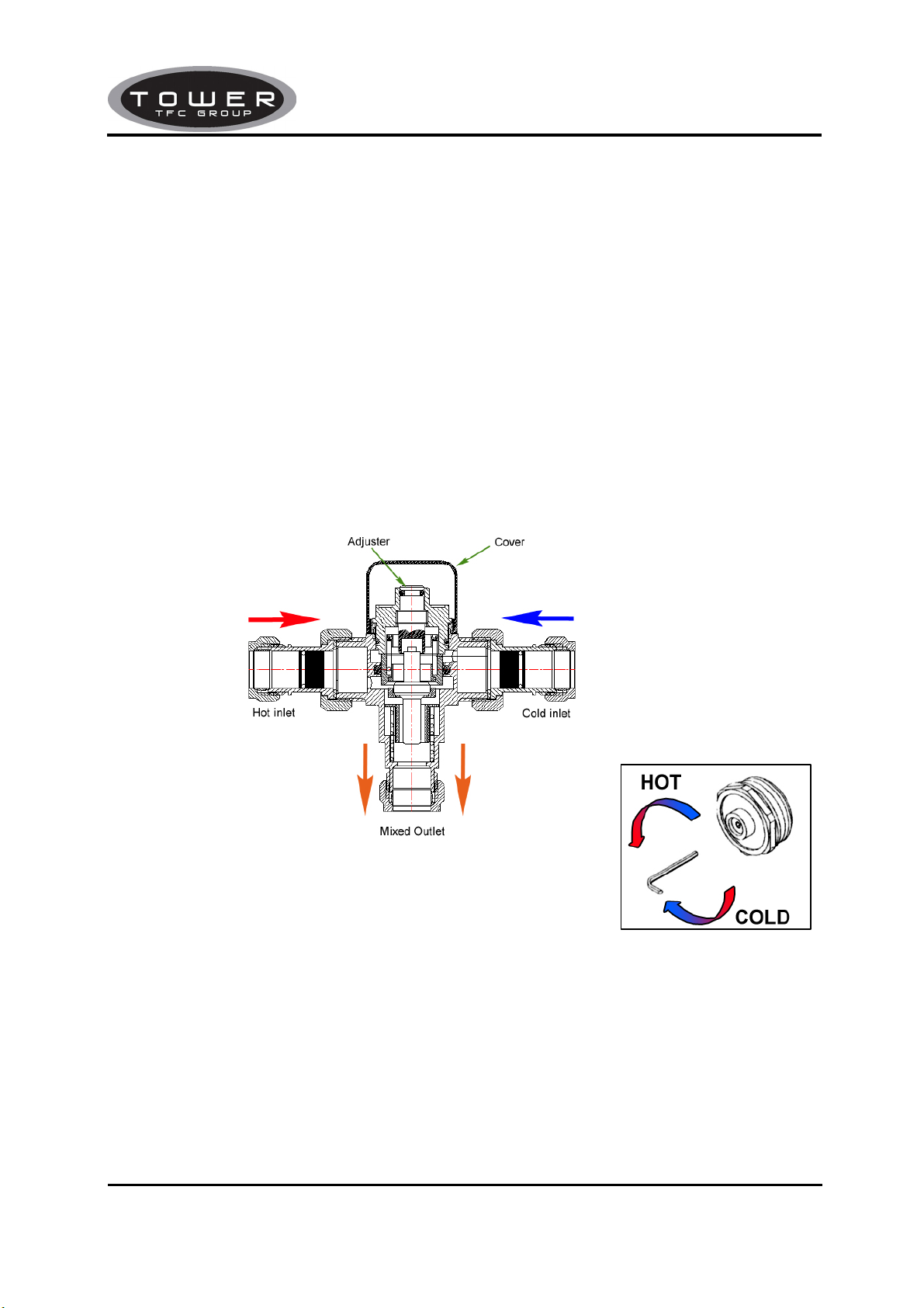
TEMPERATURE SETTING
1. Turn adjustment screw clockwise for cooler temperature,
Anti-clockwise for warmer temperature. Replace head cover.
CONDITIONS FOR NORMAL USE
In order to give compliance with N.H.S. specification D08 and TMV2 scheme, the table below lists
the conditions for normal use, the valves may perform adequately outside these parameters but the
scope of the TMV2 and TMV3 scheme does not apply. If they are required to work with other supply
conditions an engineer must carry out a risk assessment and satisfy themselves that the units are
still suitable for use.
TFC GROUP LLP Tower House, Vale Rise, Tonbridge, Kent TN9 1TB
Tel: 01732 351680 Email: sales@tfc.uk.com Web: www.tfc-group.co.uk
Page 3

Thermostatic mixing valves
Table 1: Conditions for normal use
Operating pressure range Low pressure High pressure
Maximum static pressure-bar 10 10
Flow pressure, hot and cold-bar 0.2 to 1 1 to 5
Hot supply temperature-°C
Cold supply temperature-°C
Minimum Temperature Differential
Between Mixed Temperature &
Either Supply
COMMISSIONING
Since the installed supply conditions may differ from those used in testing and setting the valves
during final inspection and a valve may have several designations, it is necessary to reset the mix
temperature. The following procedure should be used after ensuring:
a) The designation of the thermostatic mixing valve matches the intended application (i.e. if a
shower is to be supplied at 2 bar then the valve must have a HP-S designation).
b) The supply pressures match those for which the valve has been approved, see table1 and
valve details.
c) The supply temperatures are such that they are within the permitted range (see table1) and
comply with guidance information on the prevention of legionella.
Note:- If the supply conditions are not within the parameters for normal use the valve may still
be suitable, but individual engineers must carry out their own risk assessment and satisfy
themselves that the units are still suitable for use.
Adjust the mixed water temperature in accordance with table 2, the method of adjustment is
covered in the section temperature setting.
Table 2: Mixed Water Temperature
Application Abbreviated Designation
Bidet -HP-B,BE,-LP-B,BE 38 max
Shower -HP-S,SE,-LP-S,SE 41 max
Washbasin -HP-W,WE,-LP-W,WE 41 max
Bath (44°C fill)
Bath (46°C fill)
-HP-T44,-LP-T44 44 max
-HP-T46,-LP-T46 46 max
Note 1: For washbasins, washing under running water is assumed.
Note 2: Bath fill temperatures of more than 44°C should only be available when the bather is
always under the supervision of a competent person (e.g. nurse or care assistant)
Note 3: A thermostatic mixing valve having multiple designations (i.e. it is capable of satisfying
the requirements of this specification for more than one application) should be reset on site to
suit be designation required.
The following set of tests should be carried out.
1) Record the temperature of the hot and cold water supplies.
2) record the temperature of the mixed water at the largest draw-off flow rate.
3) record the temperature of the mixed water at a smaller draw-off rate, which shall be
measured.
4) Isolate the cold water supply to the mixing valve and monitor the mixed water temperature.
5) record the maximum temperature achieved as a result of (d) and the final temperature.
6) record the equipment, thermometer etc. used for the measurements.
TFC GROUP LLP Tower House, Vale Rise, Tonbridge, Kent TN9 1TB
Tel: 01732 351680 Email: sales@tfc.uk.com Web: www.tfc-group.co.uk
52-65 52-65
5 to 20 5 to 20
10°C 10°C
Mixed water temperature °C
Page 4

Thermostatic mixing valves
IN-SERVICE TESTING
The purpose of in-service testing is to regularly monitor the thermal performance of the
thermostatic mixing valve. Deterioration in performance can indicate the need for service work
to be carried out on the system.
If the authority concerned does not have a planned test and maintenance schedule then the
suggestions below should form the basis of a new system.
At intervals of 6-8 weeks and 12-15 weeks after commissioning:
a. Check supply parameters are still within the expected values if not check system for faults.
b. Carry out commissioning procedures 1) to 6) using the same test equipment, if the mixed
water temperature has changed a significant amount (by more than 1K) check to ensure
in-line filters are clean, that the check valves are working and all isolating valves are fully
open. If no fault can be found check and record the mixed water temperatures and
re-adjust mixed water temperature to the values in table 2.Complete the commissioning
procedure 1) to 6) if the mixed water temperature exceeds the values of the maximum
recorded temperature by more than 2K the need for service work is indicated.
Depending on the results of these two tests the following should be adopted.
I. If a small change (e.g.1K to 2K) occurs in one of these tests or there is no significant change
(e.g.1K maximum) then the next in service test should be 24 to 28 weeks after
commissioning.
II. If small changes occur in both test or a larger change occurs in one test (exceeding 2K) then
the next in service test should be carried out 18 to 21 weeks after commissioning.
These results can then be used to set a service interval which tests have shown can be used
with no more than a small change in mixed water temperature. This method of determining
service intervals is used to take into account various in-service conditions (i.e. water condition)
that the valve may experience.
CONNECTIONS SPECIFICATIONS
134
44.70
H
C
56
INLETS 15mm Compression
OUTLET 15mm Compression
TFC GROUP LLP Tower House, Vale Rise, Tonbridge, Kent TN9 1TB
Tel: 01732 351680 Email: sales@tfc.uk.com Web: www.tfc-group.co.uk
Page 5

Thermostatic mixing valves
SPECIFICATIONS
Minimum pressure drop through fitting for correct mixing 0.1bar (1 Metre head)
Maximum pressure drop through fitting for correct mixing 5.0bar (50 Metre head)
Maximum static pressure to be applied to fitting 10.0 bar (100 Metre head)
Maximum pressure loss ratio 20:1 either supply
Temperature stability with normal variation of supply
Temperatures and pressures
Factory set standard blend temperature Not Pre-set
Maximum hot supply temperature 80°C
The sensitive wax capsule will shut down the operation of the valve if either the hot or cold water
supply fails, provided a minimum differential of 10°C exists between the mixed water temperature
and the remaining supply.
PERFORMANCE
PRESSURE
DROP(BARS)
FLOW RATE
(LITRES/MIN)
0.1 0.2 0.4 0.6 0.8 1 1.5 2 3 4 5
5.9 9.8 14.7 18.2 21.3 23.8 30.5 35.0 42.5 49.5 55.2
Flow rates are open outlet with equal pressure drops, fitted with Check valves and Filter as
supplied.
Product Support & Guarantee
This product is guaranteed against faulty materials and workmanship for 1 year from date of
purchase. For the guarantee to be valid, the unit must be installed by a competent person, in
accordance with the instruction booklet.
This guarantee does not affect your statutory rights.
±2°C from set temperature
TFC GROUP LLP Tower House, Vale Rise, Tonbridge, Kent TN9 1TB
Tel: 01732 351680 Email: sales@tfc.uk.com Web: www.tfc-group.co.uk
 Loading...