

Page 1

Instruction Manual
TOWERSTAT RF
Selectable Volt Free
Warning – Please read this manual prior to
installation or use
Shock Hazard
This unit must be installed by a competent person,
in accordance with BS 7671 (the IEE Wiring
Regulations), or other relevant national regulations
and codes of good practice.
Always isolate the AC Mains supply before
removing the unit from the wall box.
CE
Page 2
INTRODUCTION
This thermostat can replace most common
residential thermostats and is designed to be used
with electric, gas or oil heating control systems or
cooling systems.
Unlike conventional thermostat devices, this control
is a new type of thermostat which separates the
functions into two units. The Receiver serves for
wiring connections and heat/cool on/off control The
Transmitter serves as the user interface and for
temperature sensing / control. the two units are
linked by radio frequency (RF)
The advantage is that the user can keep the
Transmitter nearby and can read / control the
temperature of the living area in immediate use.
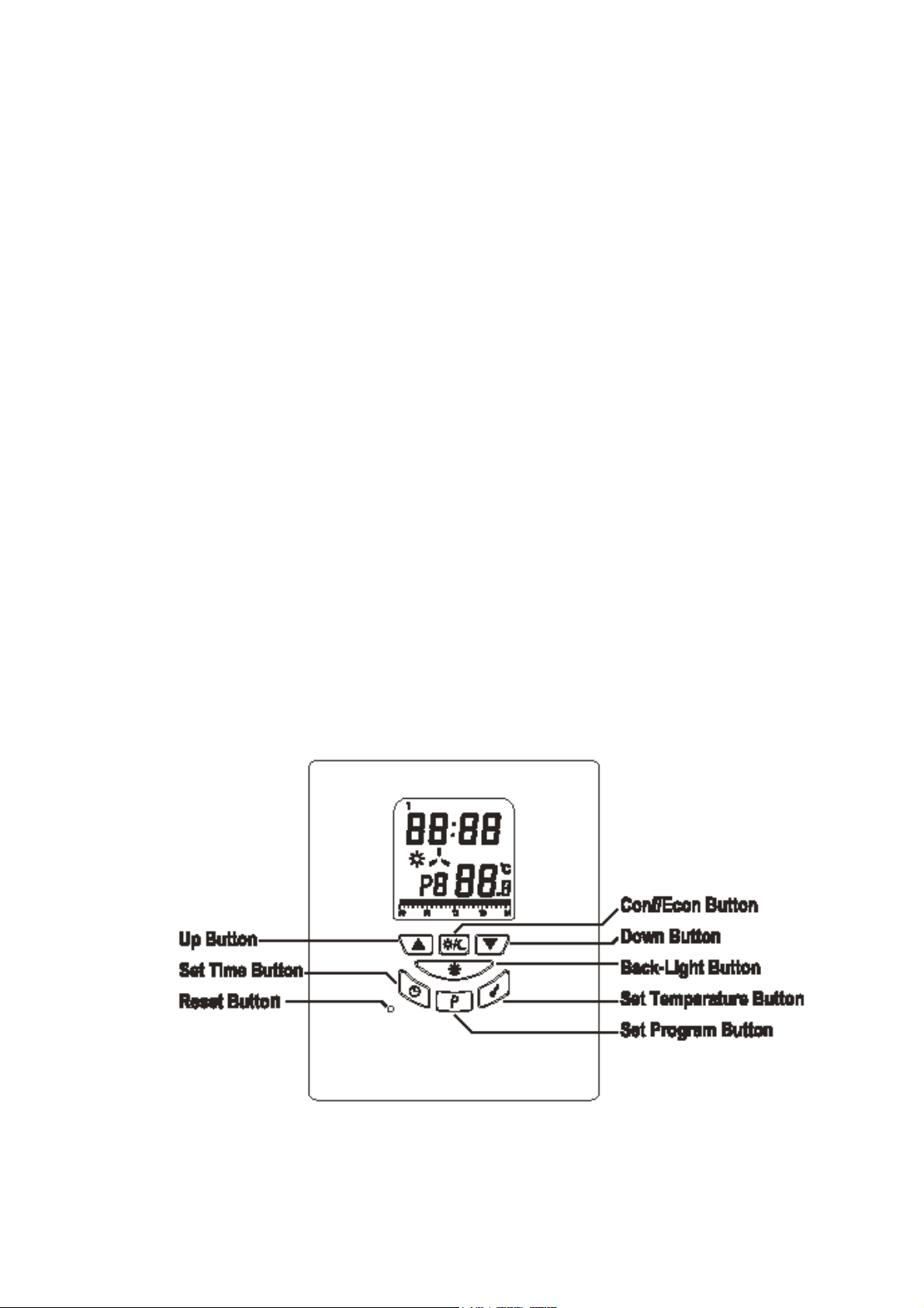
Transmitter layout:
Page 3
Page 4

Neutral
Live output
Link wire
Page 5

Features :
Several useful functions and operating modes have
been incorporated to adapt to a variety of customer
needs, as well as all the features associated with a
state of the art programmable thermostat.
Transmitter:
Can be placed anywhere in the home to detect
and control the temperature of an area of the
user’s choice. Not limited by power control
wiring locations.
Linked with the Receiver via RF. Control
distance 100m in free space.
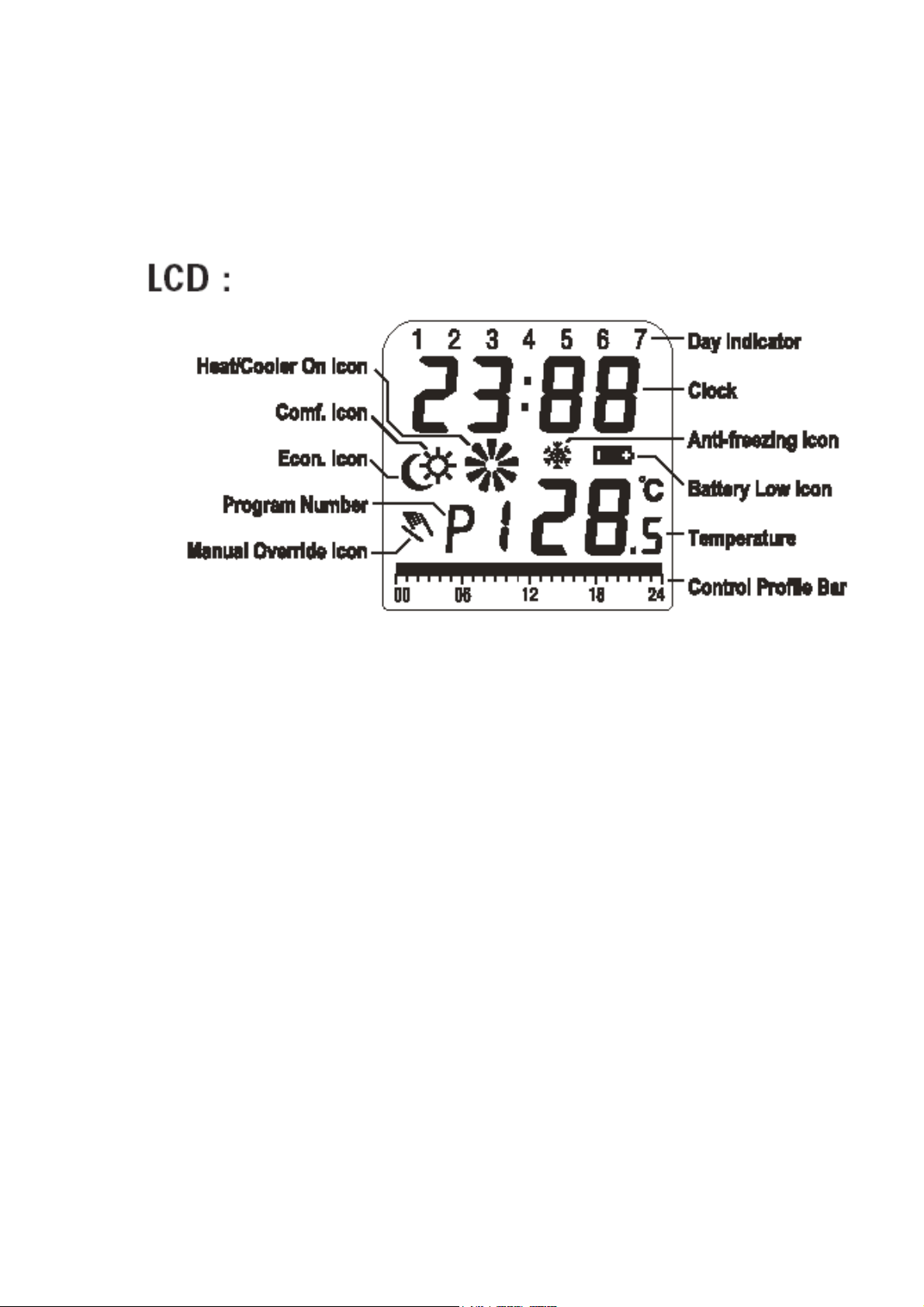
LCD shows the ‘need to know’ information only,
which is easier to understand.
Real time clock with day of the week display
Room temperature display
Control profile display
Simplified temperature adjustment – Simplified
programming procedure
6 pre-defined control profiles, 3 user
programmable control profiles
Protection against frost damage within the
heating system
Temporary override set temperature
User selectable temperature span
User selectable heater/cooler operation mode
Battery level detection
2 AA size alkaline batteries
Slim housing design
backlit display
Page 6

Receiver
Linked with Transmitter via RF
Power rating up to 230VAC 16A resistive
Powered by line voltage only. No battery
required.
Two l.e.d. indicators for power and output
status
Page 7

INSTALLATION OF RECEIVER
Caution:
1. It is recommended that this device is installed
by a qualified electrician
2. The appliance can only be mounted indoors
and in areas free from any water or moisture
3. A suitable fuse with a rating not exceeding 13A
should be in the power line
4. Wiring must conform to I.E.E. regulations
RF Address Code Setting
If there is another user nearby, e.g. in the next
dwelling, your Receiver may be operated in error
by their Transmitter. You may select a different
RF address code to prevent this. The Receiver
can only respond to a Transmitter with the same
RF coding as its own address code. Please see
the information below for an explanation of coding
changes.
1. To change the address code of the Receiver,
simply push up one or more of the 5 ‘dip’ switch
levers (see illustration below)
Push up one or more
of the white levers to
adjust Receiver
address code
Page 8

2. To change the address code of the Transmitter,
open the Transmitter housing (refer to battery
replacement section to open housing).
3. Remove one or more of the jumper links as
shown in the illustration below.
Remove one or more
of the jumper caps to
adjust the RF code
Address code # 1 – 5,
from left to right
Ensure the sequence
matches the settings
of the dip switches on
the receiver
Caution:
1. Address code of the Transmitter must be the
same as address code of Receiver. For any
jumper link removed at the Transmitter, the
corresponding dip switch lever(s) must be put
to the ‘up’ position.
2. Disconnect AC power and remove batteries
prior to adjusting address code.
Page 9

Removing your old thermostat
Caution : to avoid electric shock, isolate the power
of the heating / cooling system at the main
consumer unit in your home. Read the following
instructions carefully before disconnecting the
wires.
1. Turn off your old thermostat
2. Remove the cover from the old thermostat
3. Unscrew the old thermostat from the wall plate
4. Now find the screws attaching the wall plate to
the wall, and remove them. You should now be
able to pull the wall plate a small distance from
the wall. Do not disconnect any wires yet,
simply locate the wires.
Warning: After removing the wall plate, if you find
that it is mounted on a junction box (e.g. a box
similar to one behind a light switch or electric outlet)
it may connect to a mains voltage circuit and there
is a danger of electric shock. Please consult a
qualified electrician.
Mounting the Receiver onto the wall / junction
box:
The Receiver fixing centres may align with the
screw fixings of the existing back box. In this case:
1. Remove the front cover of the Receiver.
2. Connect the wires (see wiring diagram)
3. Securely fasten the Receiver using the
machine screws provided.
4. Replace the front cover and installation is
complete.
Page 10

Mounting the Receiver onto the optional wall
r
box:
1. Remove the front cover of the Receiver
2. Mark the holes position for the wall box
3. Drill two holes and insert the wall plugs until
they are flush with the wall surface
4. Pull the wires into the wall box and fasten the
wall box onto the wall
5. Connect the wires (see wiring diagram)
6. Securely fasten the Receiver to the wall box
with the two machine screws provided
7. Replace the front cover and installation is
complete.
Wiring for 230v or volt-free applications
The Receiver has a volt-free contact, but comes
from the factory with a pre-wired red link wire which
puts volts onto the switch. Leave the link in place
for mains switching, or remove the link for volt-free
switching.
Live supply
Live from load
Live output 230V
Switched live output
Leave red
link wire
in place
Remove
red link
wire
Connections for mains switched load:
Leave the link wire in place, and connect the
switched-live input of the load to the normally
open contact (marked SL (on)) input of the
load to the no
Neutral supply
mally open contact (marked
Neutral supply
Connections for volt-free switching:
Remove the link wire. Connect the looped
terminals of the boiler between common (marked L
in) and normally open contact (marked SL (on))
Live supply
Page 11

Setting of Transmitter
Heating / Cooling Selection
To adjust the Transmitter for heating or cooling
function, also for code changes, and to insert /
remove batteries, the Transmitter back housing
must be removed:
Once the back housing is
removed, inside the
Remove
the front
housing
Transmitter you can find
a three-position dip
switch. The three
switches control the
temperature span and set
the output for heating or
cooling function. Set the
dip switches according to
your requirements
Temperature span
selection
Span is the difference between
Push and hold
internal lock
with a
screwdriver
the turn on and turn off
temperatures. For example, in
heating systems, if you set
0
temperature to 20
C and span
to 10C, the heater will operate
when the room temperature drops to 19.50C and
turns off when the temperature rises to 20.50C. Set
the dip switches (positions 1 and 2) according to
your selection of temperature span as in the
following diagram.
Page 12

Battery installation
Your thermostat uses two ‘AA’ size
batteries to operate. To power-up
the unit, insert two ‘AA’ batteries
into the battery compartment of the
front housing. When power is
applied for the first time, the display
should show time and the day as
well as the room temperature.
Press the RESET button after
insertion of batteries (use a fine
instrument such as a straightened
paper clip to gently push the
RESET button.
After installation of the batteries,
push back the rear housing to the
control centre and then the stand.
The Transmitter is now ready to be
programmed.
Page 13

Setting the clock (refer to Transmitter layout, p.1)
1. Press the SET TIME button to clear all digits
except the day indicator the time display. The
day indicator is flashing.
2. While day indicator is flashing, press UP or
DOWN button to change the day (Day 1 =
Monday)
3. Press the SET TIME button again, the hour
digits flash. Now change the hour by pressing
the UP or DOWN button. Press and hold the
UP or DOWN buttons to speed up the
adjustment rate.
4. Press the SET TIME button again, and the
minute digits flash. Now change the minutes
by pressing the UP or DOWN button.
5. Press the SET TIME button again to return to
normal operation mode.
6. The unit will return to normal operation mode if
no key is pressed for 10 seconds.
Setting control temperature
1. Press the SET TEMPERATURE button to
display the pre-defined set temperature. The
sun symbol denotes the comfort (heating ON)
temperature setting, and the moon symbol
denotes the set-back (heating OFF)
temperature setting. Having pressed the SET
TEMPERATURE button, toggle between the
comfort or set-back temperatures by pressing
the comf/econ button.
2. Adjust either temperature to your required level
with the UP or DOWN button.
Page 14

3. Press the SET TEMPERATURE button again
to return to normal operation mode.
4. The unit will return to normal operation mode if
no button is pressed for 10 seconds
5. The default setting of comfortable mode is
210C for heater mode and 230C for cooler
mode. And the economic mode is 100C for
heater mode and 260C for cooler mode.
Setting Program
Please read through the whole of the next
section before starting to set your own
programme – whilst programming, if no button
is pressed for 10 seconds, the unit will revert to
the automatic running mode.
i) Select Week-day
Press the SET PROGRAM button. The day
indicator shows the program day and is
flashing. Press the UP or DOWN button
repeatedly to select the day or days for which
you wish to set a programme. You can select:
individual days; the whole week; the working
week, or the weekend.
ii) Select a pre-set programme
1. Press the SET PROGRAM button again, the
day indicator stops flashing and the program
number starts to flash.
Page 15

2. Scroll through the pre-set program options with
the UP or DOWN buttons – these programs
can be selected, but they cannot be altered.
Use one of the programs if they are suitable for
your requirement, or scroll to one of P7, P8 or
P9. These three program positions can be
user-adjusted to your requirement.
3. Pre-set program choices are shown below:
(solid blocks indicate comfort temperature
periods, no blocks indicate economic
temperature periods)
Page 16

4. If you wish to set your own programme
(using any of P7, P8 or P9) select one of those
program numbers and press the SET
PROGRAM button again.
5. Reading from the top, the display will show
your day selection, the hour (starting at 0 =
midnight), the sun symbol, the programme
number, and a full line of blocks along the
bottom of the screen. You can now set your
own programme, in one-hour blocks, defining
when you require comfort or economic
temperature.
6. Press the comf/econ button repeatedly to scroll
forward in one-hour periods – this will remove
the blocks visible at the bottom of the display,
thus setting economic temperature from
midnight onwards.
7. Beginning with the time you require comfort
temperature, start to scroll forward using the
UP arrow button, this will move forward in one
hour periods, leaving the blocks in place, thus
setting comfort temperature for those periods.
8. Continue setting your required programme as
in steps 6 & 7 above. You can go backwards
with the DOWN arrow button, and restore a
deleted block to set comfort temperature, or
delete a block to set economic temperature, by
pressing the comf/econ button (this button
‘toggles’ the temperature setting for the hour)
9. Once you have completed your own
programme setting, press the SET PROGRAM
button again to return to normal operating
mode.
Page 17

Testing the RF transmission range
1. Ensure the receiver is correctly wired to the
output, and that it has a mains supply
(indicated by a continuous red LED at the
receiver)
2. The transmitter display shows the current
actual temperature. Press the UP button until
the set temperature is higher than the actual
temperature.
3. After a few seconds the heater/cooler on icon is
shown – it appears as a rotating symbol above
the P number.
4. Check the green LED on the receiver. It should
be On.
5. If the LED is not On, move the Transmitter
closer to the Receiver.
6. Press the DOWN button to reduce the set
temperature below the current temperature to
turn off the demand from the receiver. The
rotating symbol will disappear, and the green
LED will go Off.
TEMPORARY OVERRIDE
Override between comfort and economic modes
1. During normal operating mode, press the
COMF/ECON button to toggle the current set
temperature to comfort or economic mode.
The HAND symbol will show with the COMF or
ECON symbol.
2. The temporary override will self-reset with the
next programmed change of temperature.
Alternatively press the COMF/ECON button to
revert to automatic operating mode
Page 18

Overriding the set temperature
1. During normal operating mode, press the UP or
DOWN arrow buttons to adjust the set
temperature point to the desired value.
2. After 10 seconds the unit will revert to normal
operating mode, but using the new adjusted
temperature as the set point. The hand symbol
will be shown in the display.
3. The temporary override will self-reset with the
next programmed change of temperature.
Alternatively revert to automatic mode by
pressing the COMF/ECON button.
FROST-PROTECTION MODE
The unit can quickly be put into frost protection
mode, for instance for periods when the property is
empty, but you wish to prevent frost damage during
cold weather.
1. Press the UP and DOWN buttons
simultaneously. The Frost Protection and
Hand symbols will be displayed.
2. Whilst Frost Protection is enabled, the
Transmitter will maintain heating to prevent the
0
temperature falling below 7
C.
BACK-LIGHT
Press the BACK-LIGHT button to turn on the backlight. The back-light will switch off when no button
is pressed for 10 seconds.
RECEIVER POWER SWITCH
There is a power switch on the Receiver. When
there is no demand for heating / cooling, it is
Page 19

recommended to turn the power switch to the Off
position.
BATTERY REPLACEMENT
The batteries should be replaced as soon as the
battery-low symbol is showing in the display. There
is a short capacitive memory which retains the
display and programme for one minute to allow for
the exchange of batteries.
1. Turn off the receiver.
2. Remove the back housing and stand of the
Transmitter.
3. Replace the old batteries with 2 good quality
AA alkaline batteries.
4. Replace the back housing and stand.
5. If operation is not as expected following battery
replacement, press reset and re-programme.
6. Turn On the power switch of the Receiver.
SPECIFICATION
Transmitter dimensions 116 x 100 x 23.5mm, weight 126g
Receiver dimensions 91.5 x 91.5 x 42mm, weight 176g
Power supply: Transmitter 2 x AA(LR6) batteries.
Receiver 230VAC 50Hz
Accuracy + / - 60 seconds / month
0
Temp. measurement 0
Temp. accuracy + / - 1
Temperature Control 7
Span 1,2,3, or 4
Air conditioner cycle time 3 minutes
Operation temperature 0
Storage temperature -10
C to 400C in 0.50C resolution
0
at 200C
0
C to 300C in 0.50C increments
0
C
0
C to 400C
0
C to 600C
Operating frequency 434 MHz
 Loading...