

Page 1

Programmable RF thermostat type RFWRT
IntroductionIntroductionIntroduction
This thermostat can replace any standard room thermostat, and is designed for use with gas or oil heating systems. If you
wish to control electric heating note that the current rating of the receiver is 3A resistive.
The transmitter is battery-powered and designed for wall mounting, using the backplate supplied. The receiver requires a
230V 50Hz supply and provides a volt-free contact to switch any load up to 3A @ 230V 50Hz.
The transmitter can be installed wherever you would normally fit a room thermostat.
The receiver should be wall-mounted close to the boiler.
The transmitter and receiver communicate with radio frequency signals.
Radio Frequency CommunicationRadio Frequency CommunicationRadio Frequency Communication
1)The factory default code for RF communication is 000. This should be changed if more than one control set is being
installed in any premises, or if unwanted operation occurs due to interference from any other radio frequency device.
See ‘F1: RF address code setting’ on the next page.
2)Ensure that different addresses are assigned to each thermostat set within the same installation. Note that there should
be a gap of at least one metre between receiver units to avoid RF interference.
3)During normal operation the transmitter sends signals at 10 minute intervals to ensure the receiver is in the correct
state. If for any reason a signal is ‘missed’ there will be a 10 minute delay until the next signal is sent. Alternatively you
can increase or decrease the temperature temporarily by pressing the up or down arrow keys. The temporary setting
will remain active until the next program time is reached.
Set time and weekday:Set time and weekday:Set time and weekday:
Insert the batteries into the transmitter; make sure that the batteries are inserted with polarity as indicated in the battery
compartment. Press and hold the select and set buttons for 3 seconds. The hour will flash—adjust with the up or down
arrow button, confirm with select button. Adjust the minute and the weekday in the same way. Press the Set button to
return to normal running mode.
Function and wiring of the receiverFunction and wiring of the receiverFunction and wiring of the receiver
1. All wiring should be carried out by a skilled person. Disconnect power before wiring. Fit a 3 Amp fuse to the receiver
supply.
2. Install the receiver adjacent to the heat source. The area should be free from any damp, or sources of electrical / magnetic interference (e.g. hi-fi speakers). The receiver should not be screened by any metal object(s).l
3. If required, change the RF address code—see ‘F1: RF address code setting’ on the next page.
4. The receiver’s red LED illuminates to confirm a mains supply is present. The green LED illuminates when the output is
on, following a demand signal being received from the transmitter.
Test the RF communicationTest the RF communicationTest the RF communication
It is important to site the transmitter and receiver in suitable locations, such that the RF signal cannot be interrupted. The
range within buildings is 20—25 metres, but this can be affected by e.g. thick stone walls, foil backed plasterboard, metal
objects such as kitchen appliances etc.
Test the set in the following way:
1. The default temperature display shows the current room temperature. Press the up button until the set temperature is 2
degrees higher than the current room temperature.
2. Wait for a few seconds. The animated flame symbol should be seen in the bottom left-hand corner of the display.
3. Check the receiver. The green LED should be visible, and (if connected) the heating system should be running.
4. Press the down button on the transmitter to reduce the temperature below the current room temperature. Wait for a few
seconds. The animated flame symbol should disappear, and the green LED at the receiver should switch off.
5. If responses do not occur as expected during steps 1—4 above, press the reset button on the transmitter and repeat
steps 1 – 4.
Wiring information:Wiring information:Wiring information:
Using the crimp connectors and insulating boots provided, connect wiring to the receiver as shown below. For conventional heating installations, connections will be required to terminals 1— 4 only. Terminal 5 can be ignored.
Wiring:Wiring:Wiring:
Push button functionPush button functionPush button function
1 N Neutral
2 L Live
3 COM Switch input—common
4 NO Switch output (On) Normally open
5 NC Switch output (Off) normally closed
Key Function
Increase setpoint temperature
Decrease setpoint temperature
Turn on backlight for 5 seconds.
SET Key for confirming and program setting
SELECT Key for program setting
RESET System reset
Activate / deactivate Frost Protection
111
Page 2
FUNCTION SETTING:FUNCTION SETTING:FUNCTION SETTING:
You can adjust the way the transmitter works, by accessing the function menu:
Access the function menu by pressing and holding the Select and Set buttons for 3 seconds. The hour will flash.
Press Select until you see the required function number flashing in the display. The function can be adjusted by
pressing the up or down arrow, then confirm with the Select button. Available functions are noted below. Note
that the device will ‘time-out’ to normal running mode if no key is pressed for 15 seconds.
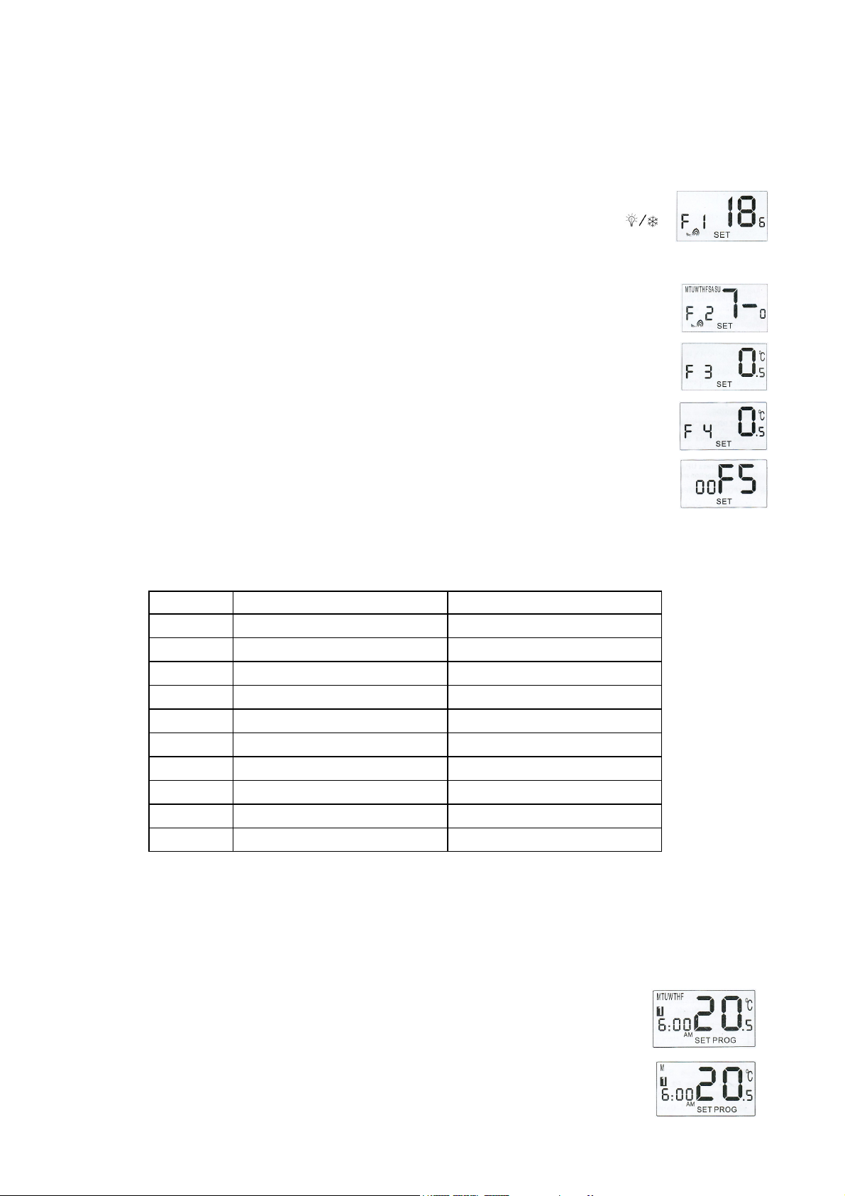
F1 = RF address code setting.
NOTE: YOU MUST CONFIRM THIS SETTING FOR THE CONTROL DEVICE TO WORK.
With mains power connected to the receiver, press the button on the side of the receiver module.
The receiver’s red and green LED’s will start flashing. Having selected F1, it will be seen that the
default value is 000, which you can adjust up to value 250. After choosing the value, press
to send the RF address to the receiver. The receiver LED’s will immediately stop flashing and the
transmitter code has been transferred to the receiver. The new code will be retained by the receiver
if power is disconnected. The address code can be changed by following this procedure at any time.
F2 = Day group or individual day selection
Day group selections are 5 — 2, or 7 — 0. If you select 5 — 2, you can programme 5 time / temperature steps throughout each day, applicable to weekdays, and 5 further time / temperature steps applicable to Saturday and Sunday. If you select 7 — 0, you can programme 5 time / temperature steps
for each individual day. Confirm your choice with the Select button.
F3 = Calibration
The default calibration (accuracy of thermostatic control), is 0.50C. You can change this to 1.00C if
you wish. Confirm with Select button.
F4 = Displayed Temperature Calibration
You can adjust the displayed temperature in the range + or — 4.00C. Confirm your choice with the
Select button.
F5 = Real-time Clock Calibration
You can adjust the accuracy of the real-time clock in the range — 35 to + 35 seconds per week. E.g.
if the clock displays a time which is slow or fast by 10 seconds over a period of one week, you can
adjust this function setting by + or — 10 in order to correct the time-keeping in subsequent weeks.
-
PrePrePre
-set program:set program:set program:
-
The RFWRT incorporates a factory pre-set program. You can view and amend any of the times or temperatures
within the pre-set program, which is shown in the table below. Note that, if no key is pressed for 15 seconds, the
device will time-out to normal running mode:
Program Weekday (Mon—Fri) Weekend (Sat, Sun)
1 Time: 6:00 a.m. Time: 6:00 a.m.
Temperature: 210C Temperature: 210C
2 Time: 8:00 a.m. Time: 8:00 a.m.
Temperature 170C Temperature 170C
3 Time: 4:00 p.m. Time: 4:00 p.m.
Temperature: 210C Temperature: 210C
4 Time: 6:00 p.m. Time: 6:00 p.m.
Temperature: 210C Temperature: 210C
5 Time: 10:00 p.m. Time: 10:00 p.m.
Temperature: 170C Temperature: 170C
REVIEW AND/OR AMEND PROGRAMME SETTINGS:REVIEW AND/OR AMEND PROGRAMME SETTINGS:REVIEW AND/OR AMEND PROGRAMME SETTINGS:
Press the Set button, the day or day group (as determined by function F2 described above), will flash. While the day
or day group is flashing, you can change to another day or day group if you wish, by pressing the up arrow button.
Confirm your choice with the Select button. You will now be viewing the pre-set program number 1. The hour will
flash, change this if required with the up or down arrow buttons. Confirm your choice with the Select button. The
minutes will flash; change this if required with the up or down arrow buttons. Confirm your choice with the Select
button. You will now be viewing the pre-set program number 2, and you can continue programming in the same
way: the flashing element in the display can be changed with the up or down arrow buttons, and the new value can
be confirmed with the Select button.
If you selected day group 5 — 2, you can review (and amend) programs 1 — 5 above for weekdays, and separately, programs 1 — 5 for weekends.
If you selected day group 7 — 0, you can review (and amend) programs 1 — 5 for every day of
the week, giving a total of 35 program settings for the whole week.
222
Page 3

Additional functions:Additional functions:Additional functions:
Frost protection: Whilst in the normal running mode, press and hold the button for 3
seconds to activate Frost Protection. The frost protection indicator shown in the illustration will
flash. While frost protection is activated, the temperature set-point is 50C. In frost protection
mode it is not possible to override the 50C temperature setting. To turn frost protection off, press
and hold the button for 3 seconds. The frost protection indicator will disappear from the
display, and normal running mode is restored.
Review temperature setting: Briefly press the up or down arrow button. The blue backlight will operate, and the
current temperature setting will be displayed (flashing). In frost protection mode, the LCD will show 50C. If the
device is in temporary override mode (see next function), the LCD will show the temporary set-point temperature.
Override (temperature adjustment): Press the up or down arrow buttons to temporarily adjust the temperature
setting: press and hold the up or down arrow button for 2 seconds. The display will show the existing temperature
setting (flashing), and then the temperature value will scroll up or down. Keep the button pressed to scroll rapidly,
or press the button repeatedly to adjust the temperature 0.50C at a time. Release the button when the new temperature is reached. The display will continue flashing for 3 — 4 seconds, and then time-out to once again show
the existing room temperature.
NOTE…. The override is a permanent adjustment of the temperature setting for the current period. The override
temperature will be stored for the current period unless adjusted back to the original temperature before the end
of the current period.
LCD backlight: The blue backlight is activated when any button is pressed, and will automatically turn off after 5
seconds. The LCD backlight will not operate when the battery is low.
Low battery warning: When the battery voltage drops below a critical level, the low-battery warning indicator will
be displayed. You should renew the batteries as soon as possible. If low batteries are left in the device, it will
eventually be unable to switch the heating on or off. The transmitter has a capacitive memory which maintains
the time and all other settings for up to one minute. If the batteries are not replaced within one minute, the transmitter will have to be re-programmed.
Sleep mode: Press and hold the up and down arrow buttons simultaneously for 3 seconds to activate sleep
mode. All functions will be paused, saving battery power. The output will be turned off immediately. The clock
will continue running. The display will show just time and weekday. Press any key to de-activate sleep mode,
and restore normal running mode.
Specification:
Transmitter: Battery powered 2 x AA (LR6) alkaline
LCD display
Blue backlight
Time display 12 hour am / pm
Time accuracy: ± 1 min / month
Operating Control range: 10—350C in 0.50C steps.
Temperature control differential: 0.50C
Frost protection temperature: 5.00C
RF transmissions at 433 MHz
Receiver: Mains powered 230V AC 50 / 60Hz
Relay output: Volt-free 3A (resistive)
Connection: 5 x DIN 6.3mm tab terminals (crimp receptacles provided)
Operating temperature range: 0 — 500C
Operating humidity range: 0—90% (non-condensing)
333
Page 4

RFWRT
Programmable thermostat
User instruction manual
 Loading...