

Page 1
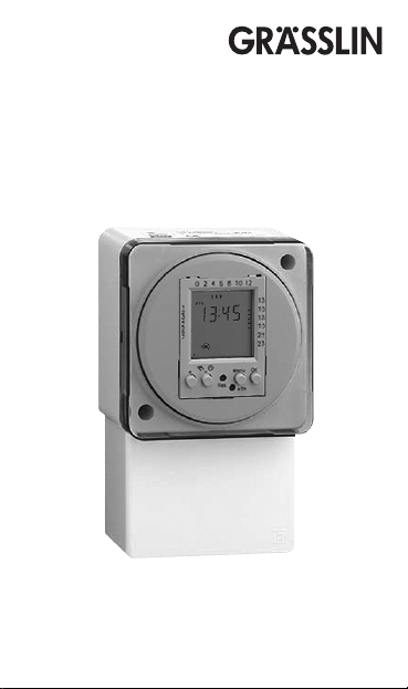
digi IHT
Immersion Heater Timer
Page 2
page
OK
reset
Prog.
P0x
pre
P0x
prog
Menu
+1h
P--
prog
del
Short description, safety remarks ........................................................... 3
Installation ..........................................................................................................4
Program structure ........................................................................................... 6
Symbols, keys.................................................................................................... 8
Setting 24h or am/pm clock, time, weekday .....................................9
Programs ...........................................................................................................10
Selection of fixed programs P01 to P03 .............................................11
Changing fixed programs P01 to P03 ..................................................12
User-defined program, P-- ........................................................................
Deleting programs ........................................................................................
Menu ....................................................................................................................17
Summer/winter time key ...........................................................................17
Automatic operation / fixed ON / fixed OFF .....................................18
Technical data .................................................................................................19
2
15
16
Page 3

Short description Immersion heater Timer digi IHT
Time control switch for electrical loads; custom designed for water
heating elements, up to the rated current (see page 19).
Safety instructions
· Installation must be carried out by a qualified electrician and
conform to current IEE regulations.
· Mains supply must be suitable fused and provision made for
Class A circuit disconnection. Ensure earth continuity is maintained
by use of the earth parking terminal.
· Time control is suitable for fixed wiring only.
3
Page 4
4
A
B
DC
1
2
3
4
5
6
7
13
15
17
19
21
23
OK
Menu
+ 1h
Res.
+ –
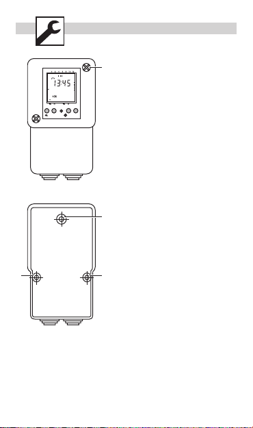
1. Switch off electrical supply to
the time control.
2. Loosen screws (A) and separate
housing from timer base.
Pull timeswitch module off
backplate.
Offer backplate to mounting
location, mark and drill in fixing
points B, C & D.
Fix backplate to wall. Push
timeswitch module on to
backplate, ensuring no
pressure is exerted on the
LCD display and ensure good
engagement with the tab
terminals.
Connect wiring as per wiring
3.
diagram securing cables /
cords with clamp provided.
NB mains supply, using fixed
wiring does not need to pass
through clamp.
4. Cut out cable entries on
underside of housing as
required.
5. Re-fit housing to timer base
and switch on electrical supply.
Page 5
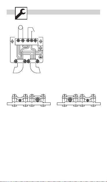
3 41
M
~
Connections:
Mains supply Immersion heater
1 Neutral 1 Neutral
3 Live 4 Live
Earth Earth
Link to 3 provided
5
Mains supply
(input)
Immersion heater
(output)
Page 6
6
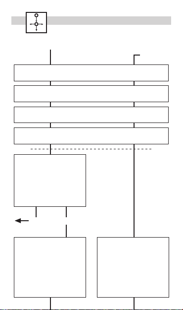
Reset (first installation)
Review / adjust
Menu
Set time: Day
Monday blinking, using +/- to select, then OK
Set time: Minute
Minute blinking, using +/- to select, then OK
Set time: Hour
Hour blinking, using +/- to select, then OK
Set time: Format 24h or am/pm
24h blinking, using +/- to select, then OK
Select Program:
P01 / P02 / P03 or P--
Using +/- to select, then OK
to set ON/OFF times
or
press Menu to escape
further programming
OKMenu
P01-03, P-Setting switching times:
First free memory location
blinks.
Press “-“ to go back one
memory location.
Press OK for setting the
switching times.
P-Setting switching times:
First free memory location
blinks.
Press “-“ to go back one
memory location.
Press OK for setting the
switching times.
Page 7

memory location.
Press OK for setting the
switching times.
memory location.
Press OK for setting the
switching times.
Set switching ON time: Hour
Hour blinking, using +/- to select, then OK
Set switching ON time: Minute
Minutes blinking, using +/- to select, then OK
Set switching ON time: Days
Mo-Su blinking, using +/- to select, then OK
Set switching OFF time: Hour
Hour blinking, using +/- to select, then OK
Set switching OFF time: Minute
Minutes blinking, using +/- to select, then OK
Set switching OFF time: Days
Mo-Su blinking, using +/- to select, then OK
Menu
RUN
A maximum of 20 memory locations
can be occupied:
10 switching ON times
10 switching OFF times
Page 8

OK
reset
1
2
3
4
5
6
7
13
15
17
19
21
23
OK
Menu
+ 1h
Res.
+ –
: Overview of daily switching program
: Setting of 24h or am/pm
: Summer/winter clock changes
: Weekday display
: Switching status display ON/OFF
: Manual operation / fixed ON / fixed OFF
: Automatic operation
8
+/- : Adjustment keys: By pressing the key longer than 2 sec.
you can adjust the timer in steps of 5 units
Res. : Reset
Menu : By pressing the menu key programming is terminated and
the system reverts to automatic operation
OK : Confirmation of programming
Page 9

OK
Menu
+ 1h
Res.
+ –
OK
Menu
+ 1h
Res.
+ –
OK
Menu
+ 1h
Res.
+ –
OK
Menu
+ 1h
Res.
+ –
1
2
3
4
5
6
7
13
15
17
19
21
23
1
2
3
4
5
6
7
13
15
17
19
21
23
1
2
3
4
5
6
7
13
15
17
19
21
23
9
1
Choose time display format
2 2 3
Set hour
1 1 2
Set minute
1 1 2
Page 10

Prog.
1
2
3
4
5
6
7
13
15
17
19
21
23
OK
Menu
+ 1h
Res.
+ –
0 24
ON
7 1812 14
0
P01 : Mo - Su, 1 x ON/OFF
24
ON
7 20
P03 : Mo - Su, 3 x ON/OFF
0
P02 : Mo - Su, 2 x ON/OFF
24
ON
7 2012 14
2220
10
1 1 2
1 = Monday 5 = Friday
2 = Tuesday 6 = Saturday
3 = Wednesday 7 = Sunday
4 = Thursday
Programs P01-P03
The switching on and off times
for programs P01 to P03 are
preset (pre).
The user can change these
programs.
Individual program, P--
Under the menu option P-- you
have the option of creating a
user-defined program.
This program can be changed
at any time. There are up to 20
memory locations available for
10 OFF and 10 ON commands.
You can allocate a corresponding
weekday or week block to each
memory location.
Page 11

P0x
pre
P0x
prog
1
2
3
4
5
6
7
13
15
17
19
21
23
OK
Menu
+ 1h
Res.
+ –
OK
Menu
+ 1h
Res.
+ –
1
2
3
4
5
6
7
13
15
17
19
21
23
11
1 1 2
1 1
Page 12

P0x
prog
1
2
3
4
5
6
7
13
15
17
19
21
23
OK
Menu
+ 1h
Res.
+ –
1
2
3
4
5
6
7
13
15
17
19
21
23
OK
Menu
+ 1h
Res.
+ –
12
1
1 1 1
‘-’: Programming the preset
memory locations
(e.g. for P02 the
memory locations
prog01 to prog04)
OK: Programming of the next
free memory location,
e.g. you should also
program:
Sa - Su
22:30 (p.m.) ON
(prog05)
23:00 (p.m.) OFF
(prog06)
Menu: Terminate programming
Page 13

P0x
prog
1
2
3
4
5
6
7
13
15
17
19
21
23
OK
Menu
+ 1h
Res.
+ –
OK
Menu
+ 1h
Res.
+ –
OK
Menu
+ 1h
Res.
+ –
1
2
3
4
5
6
7
13
15
17
19
21
23
1
2
3
4
5
6
7
13
15
17
19
21
23
1
2
3
4
5
6
7
13
Set hour
1 1 2
Set minute
1 1 2
Set week days
1 1 2
Possible week blocks and individual days
Page 14

P0x
prog
1
2
3
4
5
6
7
13
15
17
19
21
23
OK
Menu
+ 1h
Res.
+ –
1 1 2
OK
Menu
+ 1h
Res.
+ –
0 24
ON
3 20 243 20
Monday Tuesday
OFF OFF
Shift
When you are programming the switch-off command you can shift the
switch-off command by 24 hours with the “-“ key if the switch-off
command should not take place until the following day.
Example:
Mo-Fr Mo-Fr
20:00 p.m. - 03:00 a.m. ON 20:00 p.m. - 03:00 a.m. ON
03:00 a.m. - 20:00 p.m. OFF
03:00 a.m. - 20:00 p.m. OFF
Tu-Sa
14
1
Page 15

P--
prog
1
2
3
4
5
6
7
13
15
17
19
21
23
OK
Menu
+ 1h
Res.
+ –
OK
Menu
+ 1h
Res.
+ –
OK
Menu
+ 1h
Res.
+ –
OK
Menu
+ 1h
Res.
+ –
1
2
3
4
5
6
7
13
15
17
19
21
23
1
2
3
4
5
6
7
13
15
17
19
21
23
15
1
1
1 1 2
see page 11
1
Page 16

del
OK
Menu
+ 1h
Res.
+ –
1
2
3
4
5
6
7
13
15
17
19
21
23
OK
Menu
+ 1h
Res.
+ –
1
2
3
4
5
6
7
13
15
17
19
21
23
OK
Menu
+ 1h
Res.
+ –
OK
Menu
+ 1h
Res.
+ –
1
2
3
4
5
6
7
13
15
17
19
21
23
16
1 2
1
1 1
1
Page 17

Menu17+1h
OK
Menu
+ 1h
Res.
+ –
OK
Menu
+ 1h
Res.
+ –
1
2
3
4
5
6
7
13
15
17
19
21
23
Using the Menu key you can
change the following values
without a reset:
24h or am/pm : see page 7
Time : see page 7
Weekday : see page 8
P-- : see page 13
The +1h key is for the changeover
from summer to winter time.
· By pressing the
is added to the current time.
· +1h is shown on the display.
· By pressing
is subtracted from the current
time.
+1h key 1 hour
+1h again 1 hour
Page 18

Page 19

Nominal voltage 220 - 240 VAC / 50 - 60 Hz
Power consumption 5 VA at 230 V
Current output - Relay
Switching current AC
- Resistive load 16 A
- Inductive load cos. Phi 0.6 4 A
- Incandescent lamp 1000 W
Switching current DC
Minimum switching current AC 100 mA / 20 VAC
Minimum switching current DC 100 mA / 20 VDC
Battery backup (replaceable)
Operation accuracy +/- 2.5 s/d at 25 °C
Ambient temperature -10 .. +55 °C
Security level
for fitting according to instructions II
Shortest switching time
- Daily program 1 min
- Weekly program 1 min
Shortest switching interval
- Daily program 2 min
- Weekly program 2 min
2 years
Fix ON / OFF possible
Approval according to EN 60730-1
Type of connection terminals
19
Page 20

Grässlin GmbH
Bundesstraße 36
Postfach 1232
D-78104 St. Georgen/Schwarzwald
Telefon +49 (0)7724 - 933-0
Telefax +49 (0)7724 - 933-240
www.graesslin.de
info@graesslin.de
80.10.1047.7/07/02
D-78112 St. Georgen/Schwarzwald
 Loading...